Biostar P4TSP-D2 Bedienungsanleitung
Inhaltsverzeichnis
Quicklinks
P
4
T
S
P
-
D
2
P
4
T
S
P
-
D
2
P
4
T
S
P
-
D
2
FCC Information and Copyright
This equipment has been tested and found to comply with the limits of a
Class B digital device, pursuant to Part 15 of the FCC Rules. These limits
are
designed
to
provide
reasonable
protection
against
harmful
interference in a residential installation. This equipment generates, uses
and can radiate radio frequency energy and, if not installed and used in
accordance with the instructions, may cause harmful interference to radio
communications. There is no guarantee that interference will not occur in
a particular installation.
The vendor makes no representations or warranties with respect to the
contents here of and specially disclaims any implied
of
warranties
merchantability or fitness for any purpose. Further the vendor reserves
the right to revise this publication and to make changes to the contents
here of without obligation to notify any party beforehand.
Duplication of this publication, in part or in whole, is not allowed without
first obtaining the vendor's approval in writing.
The content of this user's manual is subject to be changed without notice
and we will not be responsible for any mistakes found in this user's
manual. All the brand and product names are trademarks of their
respective companies.
i
Inhaltsverzeichnis
Fehlerbehebung

Verwandte Anleitungen für Biostar P4TSP-D2


Inhaltszusammenfassung für Biostar P4TSP-D2
- Seite 1 FCC Information and Copyright This equipment has been tested and found to comply with the limits of a Class B digital device, pursuant to Part 15 of the FCC Rules. These limits designed provide reasonable protection against harmful interference in a residential installation. This equipment generates, uses and can radiate radio frequency energy and, if not installed and used in accordance with the instructions, may cause harmful interference to radio communications.
-
Seite 2: Inhaltsverzeichnis
CPU Installation ......................5 DDR DIMM Modules: DDRA1/ DDRA2 ..............6 Installing DDR Module....................6 Jumpers, Headers, Connectors & Slots..............7 DEUTSCH ....................14 Die Spezifikationen von P4TSP-D2 ................ 14 Verpackungsinhalt....................16 Einstellung der Jumper................... 16 Installation der CPU....................16 DDR-DIMM-Modules: DDRA1/ DDRA2..............17 Installation von DDR-Modul .................. -
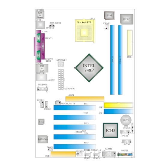
Seite 3: Layout Of P4Tsp-D2
Layout of P4TSP-D2 NOTE: ●represents the first pin. -
Seite 4: Component Index
Component Index A. Power Source Selection for Keyboard and N. Communication Network Riser Slot (CNR1) Mouse (JKBV1) O. System FAN Header (JSFAN1) B. Power Source Selection for USB P. Front USB Header (JUSB2) (JUSBV1) Q. Front USB Header (JUSB3) C. Back Panel Connector R. -
Seite 5: English
English P4TSP-D2 Features A. Hardware Provides Socket 478. Supports the Intel Pentium 4 processor to 3.2GHz. Front Side Bus at 400/533/800MHz. Supports Hyper-Threading Technology. Supports Northwood CPU. (Willamette not supported) Chipset North Bridge: Intel 848P. South Bridge: Intel ICH5. Main Memory Supports 64-bit wide DDR data channels with 1 DIMMs per-channel. -
Seite 6: Bios & Software
Supports ACPI, PCI power management. On Board AC’97 Sound Codec Chip: CMI9739A. Compliant with AC’97 specification. AC97 2.2 interface. Supports 6 channels. On Board Peripherals a. Rear side 2 serial ports. 1 parallel port. (SPP/EPP/ECP mode) Audio ports in vertical position. 1 RJ-45 LAN jack. -
Seite 7: How To Set Up Jumper
StudioFun! Application CD X 1 (optional) USB 2.0 Cable X1 (optional) S/PDIF Cable X 1 (optional) Rear I/O Panel for ATX Case X 1 Serial ATA Cable X 1 (optional) Serial ATA Power Switch Cable X 1 (optional) How to set up Jumper The illustration shows to how set up jumper. -
Seite 8: Ddr Dimm Modules: Ddra1/ Ddra2
CPU Fan Header: JCFAN1 Assignment Ground +12V JCFAN1 FAN RPM rate Sense System Fan Header: JSFAN1 Assignment Ground JSFAN1 +12V FAN RPM rate Sense DDR DIMM Modules: DDRA1/ DDRA2 DRAM Access Time: 2.5V Unbuffered/ no registered (without ECC) DDR SDRAM PC2100/ PC2700/ PC3200 Type required. -
Seite 9: Jumpers, Headers, Connectors & Slots
Jumpers, Headers, Connectors & Slots Floppy Disk Connector: FDD1 The motherboard provides a standard floppy disk connector that supports 360K, 720K, 1.2M, 1.44M and 2.88M floppy disk types. This connector supports the provided floppy drive ribbon cables. Hard Disk Connectors: IDE1/ IDE2 The motherboard has a 32-bit Enhanced PCI IDE Controller that provides PIO Mode 0~5, Bus Master, and Ultra DMA 33/ 66/ 100 functionality. - Seite 10 Front Panel Connector: JPANEL1 PWR_LED ON/OFF JPANEL1 (+) (-) HLED Assignment Function Assignment Function Speaker Sleep Control Sleep Connector Button Ground Speaker Power LED (+) POWER HDD LED (+) Hard Drive Power LED (+) HDD LED (-) Power LED (-) Ground Reset Power Button...
- Seite 11 Assignment Assignment +12V Ground JATXPWR2 +12V Ground Power Source Selection for Keyboard/ Mouse: JKBV1 JKBV1 Assignment Description +5V for keyboard and mouse Pin 1-2 close PS/2 Mouse and PS/2 Keyboard are powered with +5V standby voltage +5V Standby Voltage Pin 2-3 close Note: In order to support this function “Power-on system via keyboard and mouse”, “JKBV1”...
- Seite 12 Note: In order to support this function “Power-on system via USB device”, “JUSBV1/JUSBV2/ JUSBV3_4” jumper cap should be placed on pin 2-3 individually. Clear CMOS Jumper: JCMOS1 JCMOS1 Assignment Normal Operation (default) Pin 1-2 Close Clear CMOS Data Pin 2-3 Close ※...
- Seite 13 AUDIO DJ Connector: JDJ1 Assignment Assignment SMBDATA SMBCLK INT_B JDJ1 ATX_PWROK Game Header: JGAME1 JGAME1 Assignment Assignment Joystick B Button 1 Joystick A Button 1 Joystick B Coordinate X Joystick A Coordinate X MIDI Output Ground Joystick B Coordinate Y Ground Joystick B Button 2 Joystick A Coordinate Y...
- Seite 14 Mic Power/ Bass Audio Power Right Line Out/ Speaker Out Right Line Out/ Speaker Out Right Right Reserved Left Line Out/ Speaker Out Left Line Out/ Speaker Out Left Left Right Line In/ Rear Speaker Right Line In/ Rear Speaker Right Right Left Line In/ Rear Speaker Left Left Line In/ Rear Speaker Left...
- Seite 15 Back Panel Connectors JRJ45USB1 JKBMS1 JPRNT1 PS/2 (optional) Mouse Line In JUSB1 Parallel Port Speaker Out MIC In PS/2 COM1 COM2 Keyboard JCOM1 JCOM2 JAUDIO 6 Channel Speakers Line In/ Rear Speaker Speaker Out Mic In/ Center & Bass...
-
Seite 16: Deutsch
Deutsch Die Spezifikationen von P4TSP-D2 A. Hardware Uterstützung für Sockel 478. ® Unterstützung für den Intel Pentium 4 Prozessor bis zu 3.2GHz. FSB mit 400/533/800MHz. Uterstützung für die Hyper-Threading Technologie. Unterstützung für Intel CPU Northwood. (Willamette wird nicht untergestützt) Chipsatz Die Northbridge: Intel 848P. - Seite 17 Unterstützung für 10 Mb/s, 100 Mb/s und 1000Mb/s Auto-Negotiation. Halb/Voll-Duplex Fähigkeit. Unterstützung für ACPI, PCI Power Management. Onboard AC’97 Sound Codec Chip: CMI9739A. Entspricht der Spezifikation von AC’97. AC97 2.2 Interface. Unterstützung für 6-Kanal. Onboard-Peripheriegeräte a. Rückwand 2 serielle Schnittstellen. 1 parallele Schnittstelle.
-
Seite 18: Verpackungsinhalt
Verpackungsinhalt HDD Kable X 1 FDD Kable X 1 Benutzer Handbuch X1 Treiber CD für Installation X1 StudioFun! Anwendung CD X 1 (optional) USB 2.0 Kable X1 (optional) S/PDIF Kable X 1 (optional) I/O-Rückwand für ATX Gehäuse X 1 Serial ATA Kable X 1 (optional) Serial ATA Netzschalter Kable X 1 (optional) Einstellung der Jumper Die Abbildung verdeutlicht, wie Jumper eingestellt werden. -
Seite 19: Ddr-Dimm-Modules: Ddra1/ Ddra2
Sie die Installation. Schritt 1 Schritt 2 Schritt 3 Schritt 4 CPU-Lüfter Header: JCFAN1 Beschreibung Masse +12V JCFAN1 Lüfter RPM Geschwindigkeit Sensor System-Lüfter Header: JSFAN1 Beschreibung Masse JSFAN1 +12V Lüfter RPM Geschwindigkeit Sensor DDR-DIMM-Modules: DDRA1/ DDRA2 DRAM-Zugriffszeit: 2.5V unbuffered/ nicht registrierter (ohne ECC) DDR SDRAM PC2100/ PC2700/ PC3200 Typ erforderlich. -
Seite 20: Installation Von Ddr-Modul
Installation von DDR-Modul Öffnen Sie einen DIMM-Slots, indem Sie die seitlich Chips nach außen drücken. Richten Sie das DIMM-Modul so über dem Slot aus, dass das Modul mit der Kerbe in den Slot passt. Drücken Sie das DIMM-Modul in den Slot, bis die seitlichen Clips zuschnappen und das Modul fest sitzt. - Seite 21 die der Spezifikation von SATA 1.0 entspricht ( Dtenübertragung mit 1.5Gb/S) Anschlüsse für die Vorderseite: JPANEL1 PWR_LED ON/OFF JPANEL1 (+) (-) HLED Belegung Funktion Belegung Funktion Schlaf- Kontroll Schlaf- Lautsprecher- Knopf Kein Masse Anschluss Kein Kein Kein Lautsprecher Power LED (+) POWER HDD LED (+) Festplatte...
- Seite 22 Belegung Belegung +12V Masse JATXPWR2 +12V Masse Auswahl von Stromsmodi für Tastatur/ Maus: JKBV1 JKBV1 Pin-Belegung Beschreibung +5V für Tastatur und Maus Pin 1-2 geschlossen Durch +5V reservierte Spannung für +5V reservierte PS/2-Maus und PS/2-Tastatur zum Spannung Erwecken vom System Pin 2-3 geschlossen Anmerkung: Um die Funktion ─...
-
Seite 23: Jumper Zum Löschen Des Cmos: Jcmos1
JUSBV1: 5V reservierte Spannung für JUSB1 zum Erwecken JUSBV2: 5V reservierte Spannung für JRJ45USB1 zum Erwecken +5V reservierte Spannung JUSBV3_4: 5V reservierte Spannung Pin 2-3 geschlossen für JUSB2/3 zum Erwecken Anmerkung: Um die Funktion ─ “Erwecken durch USB-Geräte“ ─ zu aktivieren, müssen Pins 2-3 von “JUSBV1/JUSBV2/ JUSBV3_4”durch die Jumperkappe verdeckt werden. - Seite 24 Warnmeldung für Chassis-Öffnen Anschluss: JCL1 Belegung Warnmeldung für Chassis-Öffnen JCL1 Masse AUDIO DJ Anschluss: JDJ1 Belegung Belegung SMBDATA SMBCLK INT_B Schlüsse JDJ1 ATX_PWROK Game Header: JGAME1 JGAME1 Belegung Belegung Joystick B Knopf 1 Joystick A Knopf 1 Joystick B Koordierung X Joystick A Koordierung X MIDI Ausgabe Masse...
- Seite 25 Digital Audio Anschluss: JSPDIF_OUT1 Belegung SPDIF_Ausgabe JSPDIF_OUT1 Masse Front Panel Audio Header: JAUDIO1 JAUDIO1 Belegung Belegung Mikrofon-Eingang/ Masse Zentrum Mikrofon-Betriebsspannung Audio-Betriebsspannung /Bass Audio-Signal des rechten Audio-Signal des rechten Kanals zur Kanals zur Vorderseite / Vorderseite / Lautsprecher-Signal Lautsprecher-Signal des rechten des rechten Kanals zur Vorderseite Kanals zur Vorderseite Reservieret für spät.
-
Seite 26: Anschlüsse Für Die Rückwand
Masse Wake-up WOL1 Front USB Header: JUSB2, JUSB3 Belegung Belegung +5V(geschmelzt) +5V(geschmelzt) USB- USB- USB+ USB+ Masse Masse JUSB2/3 Schlüsse Kein Anschlüsse für die Rückwand... -
Seite 27: Warpspeeder
6 K anal Lautsprecher Line-In/ R cklautsprecher ü Lautsprecher Ausgang/ (L/R) Fornt-Lautsprecher Mikrofon Eingang/ (L/R) Zentrallautsprecher & Bass WarpSpeeder Introduction [ WarpSpeeder™ ], a new powerful control utility, features three user-friendly functions including Overclock Manager, Overvoltage Manager, and Hardware Monitor. -
Seite 28: System Requirement
With the Overclock Manager, users can easily adjust the frequency they prefer or they can get the best CPU performance with just one click. The Overvoltage Manager, on the other hand, helps to power up CPU core voltage and Memory voltage. The cool Hardware Monitor smartly indicates the temperatures, voltage and CPU fan speed as well as the chipset information. -
Seite 29: Usage
When you see the following dialog in setup procedure, it means setup is completed. If the “Launch the WarpSpeeder Tray Utility” checkbox is checked, the Tray Icon utility and [WarpSpeeder™] utility will be automatically and immediately launched after you click “Finish” button. Usage The following figures are just only for reference, the screen printed in this user manual will change according to your motherboard on hand. - Seite 30 [WarpSpeeder™] includes 1 tray icon and 5 panels: 1. Tray Icon: Whenever the Tray Icon utility is launched, it will display a little tray icon on the right side of Windows Taskbar. This utility is responsible for conveniently invoking [WarpSpeeder™] Utility. You can use the mouse by clicking the left button in order to invoke [WarpSpeeder™] directly from the little tray icon or you can right-click the little tray icon to pop up a popup menu as following figure.
- Seite 31 Duck walking => overclock percentage from 100% ~ 110 % Duck running => overclock percentage from 110% ~ 120% Duck Burning => overclock percentage from 120% ~ above 3. Voltage Panel Click the Voltage button in Main Panel, the button will be highlighted and the Voltage Panel will slide out to up as the following figure.
- Seite 33 4. Overclock Panel Click the Overclock button in Main Panel, the button will be highlighted and the Overclock Panel will slide out to left as the following figure. Overclock Panel contains the these features: “–3MHz button”, “-1MHz button”, “+1MHz button”, and “+3MHz button”: provide user the ability to do real-time overclock adjustment.
- Seite 34 “Auto-overclock button”: User can click this button and [ WarpSpeeder™ ] will set the best and stable performance and frequency automatically. [ WarpSpeeder™ ] utility will execute a series of testing until system fail. Then system will do fail-safe reboot by using Watchdog function. After reboot, the [ WarpSpeeder™ ] utility will restore to the hardware default setting or load the verified best and stable frequency according to the Recovery Dialog’s setting.
- Seite 35 5. Hardware Monitor Panel Click the Hardware Monitor button in Main Panel, the button will be highlighted and the Hardware Monitor panel will slide out to left as the following figure. In this panel, you can get the real-time status information of your system. The information will be refreshed every 1 second.
- Seite 36 Note: Because the overclock, overvoltage, and hardware monitor features are controlled by several separate chipset, [ WarpSpeeder™ ] divide these...
-
Seite 37: Studiofun
features to separate panels. If one chipset is not on board, the correlative button in Main panel will be disabled, but will not interfere other panels’ functions. This property can make [ WarpSpeeder™ ] utility more robust. StudioFun! Introduction StudioFun! is a media-player based on optimized GNU/Linux distribution to bring a “Room Theater”... -
Seite 38: Error Messages
StudioFun! Install This option will do the basic installation of the distribution. The installation works on pre-installed windows or GNU/Linux distribution. On selecting the “StudioFun Install” option the installer boots and displays a dialog box indicating the space required and waits for a confirmation. Selecting “Ok” will continue the installation while selecting “Cancel”... -
Seite 39: Booting To Studiofun
unsupported and undocumented hardware the above error message is popped. 4. No device found! This error message is given if there is no hard disk in the system. StudioFun! Recover Where there is a MBR (Master Boot record) corruption, the “StudioFun Recover” will automatically probe the hard disk master boot record and find out the installed operating system(s). -
Seite 40: Media Control
a complete description of the Desktop application. Desktop This is the main shell of the StudioFun! software. It illustrates two main categories, one is the main "Media Control" part and the other is the "Control Panel". Media control The Media Control consists of the following functionalities: This control icon will glow whenever a VCD is detected in a DVD/CD-ROM drive. -
Seite 41: Control Panel
This control will glow whenever a DVD is detected in a DVD drive. The DVD will be auto-played only when it is put in to the drive when the Desktop (StudioFun! shell) is up and running, otherwise, the control will simply glow to inform the user about a DVD present in the DVD/CD-ROM. - Seite 42 2. Screensaver Clicking this icon will invoke the screensaver application. Refer to section 5.3 Screensaver for more details. 3. Display Settings Clicking this icon will invoke the application for changing the screen resolutions. Refer to section 5.4, Display Settings for more details. 4.
-
Seite 43: Software Details
Software Details XINE XINE is a multimedia player. It plays back Audio CD, DVD, and VCD. It also decodes multimedia files like AVI, MOV, WMV, and MP3 from local disk drives. It interprets most of the common multimedia formats. • Features of Xine Skinnable GUI Navigation controls (seeking, pause, fast, slow, next chapter, etc) - Seite 44 MPEG-Audio (.mp2, .mp3) WAV (.wav) Video CODEC MPEG 1/2 MPEG 4 (aka OpenDivX) MS MPEG 4 Chapter 5: Software Details 10 Windows Media Video 7 m. Motion JPEG • Remote Control Support. Infrared interface User-friendly • Usage of StudioFun! with CelomaChrome skin Select VCD button to play a VCD disc Select DVD button to play a DVD disc Select CDDA button to play a Audio CD...
-
Seite 45: Select Region
m. Select “menu” button to use menu while playing DVD n. Select “control” button to adjust brightness / color o. Select “setup” button to modify the settings of the player p. Select ”f.scr” button to show the video output of the player in full screen mode q. -
Seite 46: Screensaver
Screensaver Screensaver The xscreensaver daemon waits until the keyboard and mouse have been idle for a period, and then runs a graphics demo chosen at random. The demo is terminated as soon as there is any mouse or keyboard activity. The xscreensaver-demo program is the graphical user interface to xscreensaver. -
Seite 47: Display Settings
various graphics demos randomly 2. Only one Screen Saver: When user chooses this option, screensaver displays only one graphics demo. 3. Blank Screen Only: When user chooses this option, screensaver only blanks the screen instead of displaying the graphics demo. 4. -
Seite 48: File Manager
By default user of StudioFun! will be given a choice to select between any of the following three resolutions. • 640x480 • 800x600 • 1024x768 The current resolution of the Display will be selected by default. It requires restart of the StudioFun! to reflect the changes made. -
Seite 50: Trouble Shooting
Trouble Shooting PROBABLE SOLUTION No power to the system at all Power light don’t * Make sure power cable is securely plugged in illuminate, fan inside power supply does not turn * Replace cable on. Indicator light on keyboard does not turn on * Contact technical support PROBABLE SOLUTION... -
Seite 51: Problemlösung
Problemlösung MÖGLICHE URSACHE LÖSUNG Das System hat keine Spannungsversorgung. * Versichern Sie sich, dass das Stromkabel richtig Die Stromanzeige leuchtet nicht, der Lüfter im angebracht ist Inneren Stromversorgung wird nicht * Ersetzen Sie das Stromkabel eingeschaltet. Tastaturleuchten sind nicht an. * Wenden Sie sich an Ihre Kundendienststelle MÖGLICHE URSACHE LÖSUNG... - Seite 52 08/4/2003...