Biostar m7vit grand Benutzerhandbuch
Inhaltsverzeichnis
Quicklinks
M
7
V
I
T
G
r
a
n
d
M
7
V
I
T
G
r
a
n
d
M
7
V
I
T
G
r
a
n
d
FCC Information and Copyright
This equipment has been tested and found to comply with the limits of a
Class B digital device, pursuant to Part 15 of the FCC Rules. These limits
are
designed
to
provide
reasonable
protection
against
harmful
interference in a residential installation. This equipment generates, uses
and can radiate radio frequency energy and, if not installed and used in
accordance with the instructions, may cause harmful interference to radio
communications. There is no guarantee that interference will not occur in
a particular installation.
The vendor makes no representations or warranties with respect to the
contents here of and specially disclaims any implied
of
warranties
merchantability or fitness for any purpose. Further the vendor reserves
the right to revise this publication and to make changes to the contents
here of without obligation to notify any party beforehand.
Duplication of this publication, in part or in whole, is not allowed without
first obtaining the vendor's approval in writing.
The content of this user's manual is subject to be changed without notice
and we will not be responsible for any mistakes found in this user's
manual. All the brand and product names are trademarks of their
respective companies.
i
Inhaltsverzeichnis
Fehlerbehebung

Verwandte Anleitungen für Biostar m7vit grand


Inhaltszusammenfassung für Biostar m7vit grand
- Seite 1 FCC Information and Copyright This equipment has been tested and found to comply with the limits of a Class B digital device, pursuant to Part 15 of the FCC Rules. These limits designed provide reasonable protection against harmful interference in a residential installation. This equipment generates, uses and can radiate radio frequency energy and, if not installed and used in accordance with the instructions, may cause harmful interference to radio communications.
-
Seite 2: Inhaltsverzeichnis
DIMM Modules: DIMM1, DIMM2 ................6 Installing DIMM Module ..................... 7 Jumpers, Headers, Connectors & Slots..............7 DEUTSCH ....................14 Spezifikationen von M7VIT Grand ................14 Verpackungsinhalt....................15 Einstellung der Jumper................... 16 Installation der CPU....................16 DIMM-Modulen: DIMM1, DIMM2 ................17 Installation von DDR-Module .................. - Seite 3 Display Settings....................... 47 File Manager......................47 TROUBLE SHOOTING .................49 PROBLEMLÖSUNG ................50...
-
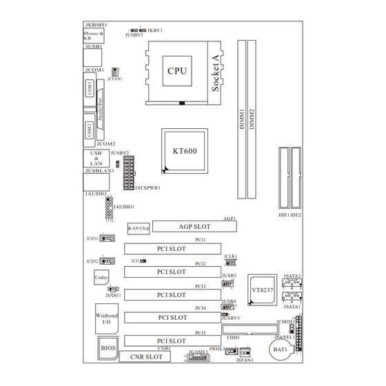
Seite 4: Layout Of M7Vit Grand
Layout of M7VIT Grand JKBV1 JUSBV1 KT600 JUSBV2 JATXPWR1 JAUDIO1 IDE1 IDE2 AGP SLOT LAN Chip PCI1 PCI SLOT PCI2 PCI SLOT JUSB3 JSATA2 Codec PCI3 VT8237 PCI SLOT JUSB4 JSATA1 PCI4 Winbond PCI SLOT JUSBV3 JCMOS1 PCI5 JPANEL1 FDD1... -
Seite 5: Component Index
Component Index KT600 LAN Chip Codec SATA1 VT8237 SATA1 Winbond BIOS BAT1 A. Power Source Selection for Keyboard M. Communication Network Riser Slot and mouse (JKBV1) (CNR1) B. Power Source Selection for USB N. Game Header (JGAME1) (JUSBV1) O. Floppy Disk Connector (FDD1) C. -
Seite 6: English
English M7VIT Grand Features A. Hardware Provides Socket A. Supports Single Socket A for an AMD Athlon/ Duron Family processor Front Side Bus at 200/266/333/400 MHz. Chipset North Bridge: VIA KT600. South Bridge: VIA VT8237. Main Memory Supports up to 2 DDR devices. -
Seite 7: Bios & Software
1 parallel port. (SPP/EPP/ECP mode) Audio ports in vertical position. 1 LAN jack. PS/2 mouse and PS/2 keyboard. 4 USB2.0 ports. b. Front Side 1 floppy port supports 2 FDDs with 360K, 720K, 1.2M, 1.44M and 2.88Mbytes. 4 USB2.0 ports. 1 front audio header. -
Seite 8: How To Setup Jumper
How to setup Jumper The illustration shows how jumpers are setup. When the Jumper cap is placed on pins, the jumper is “close”. If no jumper cap is placed on the pins, the jumper is ”open”. The illustration shows a 3-pin jumper whose pin 1and 2 are “close” when jumper cap is placed on these 2 pins. -
Seite 9: Dimm Modules: Dimm1, Dimm2
CPU Fan Header: JCFAN1 Pin No. Assignment Ground +12V FAN RPM rate Sense System Fan Header: JSFAN1 Pin No. Assignment Ground +12V FAN RPM rate Sense DIMM Modules: DIMM1, DIMM2 DRAM Access Time: 2.5V Unbuffered/ Registered DDR PC1600/ 2100/ 2700/ 3200 Type required. -
Seite 10: Installing Dimm Module
Installing DIMM Module Unlock a DIMM slot by pressing the retaining clips outward. Align a DIMM on the slot such that the notch on the DIMM matches the break on the slot. Insert the DIMM firmly and vertically into the slot until the retaining chip snap back in place and the Dimm is properly seated. - Seite 11 Front Panel Connector: JPANEL1 PWR_LED ON/OFF (+) (-) HLED Assignment Function Assignment Function Sleep Control Sleep Speaker Button Ground Connector Speaker Power LED (+) POWER HDD LED (+) Hard Drive Power LED (+) HDD LED (-) Power LED (-) Ground Reset Power Button Power-on...
- Seite 12 Power Connectors: JATXPWR1 Assignment Assignment +3.3V +3.3V +3.3V -12V Ground Ground PS_ON Ground Ground Ground Ground Ground PW_OK Standby Voltage +12V Power Source Selection for Keyboard/ Mouse: JKBV1 JKBV1 Assignment Description +5V for keyboard and mouse Pin 1-2 close PS/2 Mouse and PS/2 Keyboard are +5V Standby powered with +5V standby voltage Voltage...
- Seite 13 Power Source Selection for USB: JUSBV1/ JUSBV2/ JUSBV3 JUSBV1/JUSBV2/ Assignment Description JUSBV3 JUSBV1: 5V for USB at the JUSB1 connector port Pin 1-2 close JUSBV2: 5V for JUSBLAN1 port JUSBV3: 5V for JUSB3/4 ports JUSBV1: JUSB1 port powered with +5V Standby standby voltage of 5V Voltage Pin 2-3 close...
- Seite 14 2. Set the jumper to “Pin2-3 Close.” 3. Wait for five seconds. 4. Set the jumper to “Pin 1-2 Close.” 5. Power on the AC. 6. Reset your desired password or clear the CMOS data. Case Open Connector: JCI1 Assignment Case Open Signal Ground CD-ROM Audio-In Header: JCDIN1/ JCDIN2...
- Seite 15 Digital Audio Connector: JSPDIF1 Assignment SPDIF_OUT Ground Game Header: JGAME1 Assignment Assignment Joystick B Button 1 Joystick A Button 1 Joystick B Coordinate X Joystick A Coordinate X MIDI Output Ground Joystick B Coordinate Y Ground Joystick B Button 2 Joystick A Coordinate Y MIDI Input Joystick A Button 2...
- Seite 16 Back Panel Connectors JKBMS1 JUSBLAN1 JPRNT1 PS/2 Mouse Parallel Line In JUSB1 Speaker Out MIC In PS/2 COM1 COM2 Keyboard JCOM1 JCOM2 JAUDIO 6 Channel Speakers Line In/ Rear Speaker Speaker Out Mic In/ Center & Bass...
-
Seite 17: Deutsch
Deutsch Spezifikationen von M7VIT Grand A. Hardware Unterstützung für Sockel A. ® Unterstützung für die AMD Athlon/ Duron-Familie Prozessoren. FSB mit 200/266/333/400 MHz. Chipsatz Northbridge: VIA KT600. Southbridge: VIA VT8237. Hauptspeicher Unterstützung für 2 DDR Geräte. Unterstützung für 200/266/333/400 MHz Hochgeschwindigkeit DDR Spreicher. -
Seite 18: Verpackungsinhalt
Audio Schnittstellen in vertikale Stellung.(Lin-In/Speaker-Out/Mic-In) 1 LAN-Buchse. Unterstützung für PS/2-Maus und PS/2-Tastatur. 4 USB 2.0-Ports. b. Für Vorderseite 1 Floppy-Port mit Unterstützung für 2 Diskettenlaufwerke.(360KB, 720KB, 1.2MB, 1.44MB und 2.88MB) 4 USB2.0 ports 1 Front-Audio-Header. Abmessungen ATX Form-Factor: 24.5cm X 30.5cm (W X L) B. -
Seite 19: Einstellung Der Jumper
Einstellung der Jumper Die Abbildung verdeutlicht, wie Jumper eingestellt werden. Pins werden durch die Jumper-Kappe verdeckt, ist der Jumper ”geschlossen”. Keine Pins werden durch die Jumper-Kappe verdeckt, ist der Jumper “geöffnet”. Die Abbiildung zeigt einen 3-Pin Jumper dessen Pin1 und Pin2 ”geschlossen“ sind, bzw. es befindet sich eine Jumper-Kappe auf diesen beiden Pins. -
Seite 20: Dimm-Modulen: Dimm1, Dimm2
CPU-Lüfter Headers: JCFAN1 Belegung Masse +12V FAN RPM Sensor RPM: “Rounds per Minute”, deutsch: Umdrehungen pro Minute. System -Lüfter Headers: JSFAN1 Belegung Masse +12V FAN RPM Sensor DIMM-Modulen: DIMM1, DIMM2 DRAM-Zugriffszeit: 2.5V unbuffered / registered DDR PC1600/ 2100/ 2700/ 3200 Typ erforderlich. -
Seite 21: Installation Von Ddr-Module
Installation von DDR-Module Öffnen Sie einen DIMM-Slots, indem Sie die seitlich Chips nach außen drücken. Richten Sie das DIMM-Modul so über dem Slot aus, dass das Modul mit der Kerbe in den Slot passt. Drücken Sie das DIMM-Modul in den Slot, bis die seitlichen Clips zuschnappen und das Modul fest sitzt Jumpers, Headers, Anschlüsse &... - Seite 22 Anschlüsse für die Vorderseite: JPANEL1 PWR_LED ON/OFF JPANEL1 (+) (-) HLED Belegung Funktion Belegung Funktion Schlaf- Kontroll Schlaf- Lautsprecher- knopf Kein Masse Anschluss Kein Kein Kein Lautsprecher Power LED (+) POWER HDD LED (+) Festplatte Power LED (+) HDD LED (-) Power LED (-) Masse Rückstell-...
- Seite 23 Stromversorgunsanschluss: JATXPWR1 Belegung Assignment +3.3V +3.3V +3.3V -12V Masse Masse PS_ON Masse Masse Masse Masse Masse PW_OK +5V_SB +12V Auswahl von Stromsmodi für Tastatur/ Maus: JKBV1 JKBV1 Belegung Beschreubung +5V für Tasratur und Maus Pin 1-2 geschlossen Durch +5V reservierte Sapnnung für PS/2-Tastatur reservierte und PS/2-Maus zum Erwecken...
-
Seite 24: Jumper Zum Löschen Des Cmos: Jcmos1
JUSBV1: +5V reservierte Sapnnung für den USB-Port von JUSB1 zum reservierte Erwecken Spannung JUSBV2: +5V reservierte Sapnnung für Pin 2-3 geschlossen den USB-Port von JUSBLAN1 zum Erwecken JUSBV3: +5V reservierte Sapnnung für den USB-Port von JUSB3/4 zum Erwecken Anmerkung: Um die Funktion ─ Erwecken durhj USB ─ zu aktivieren, müssen Pins2-3 von JUSBV1/JUSBV2/JUSBV3 durch die Jumperkappe verdeckt werden. -
Seite 25: Warnmeldung Für Chassis-Öffnen Anschluss: Jci1
Warnmeldung für Chassis-Öffnen Anschluss: JCI1 Belegung Warnmeldung für Chassis Öffnen Masse CD-ROM Audio-In Header: JCDIN1/ JCDIN2 Belegung Eingabe von linken Kanal Masse Masse Eingabe von rechten Kanal Digital Audio Anschluss: JSPDIF1 Belegung S/PDIF_Ausgang Masse Front Panel Audio Header: JAUDIO1 Belegung Belegung Mikrofon-Eingang/Zentrum Masse... -
Seite 26: Frequenz Auswahl: Jclk1
Audio-Signal des rechten Kanals Audio-Signal des rechten Kanals von der Vorderseite / von der Vorderseite/ Lautsprecher-Signal des rechten Lautsprecher-Signal des rechten Kanals von der Vorderseite Kanals von der Vorderseite Audio-Signal des linken Kanals Audio-Signal des linken Kanals von der Vorderseite/ von der Vorderseite/ Lautsprecher-Signal des linken Lautsprecher-Signal des linken... - Seite 27 Anschlüsse für die Rückwand JKBMS1 PS/2- JPRNT1 JUSBLAN1 Audio-Signal Maus Parallel -Eingang Lautsprecher- Ausgang Mikrofon- Eingang PS/2 COM1 COM2 Tastatur JUSB1 JCOM1 JCOM2 JAUDIO 6-Kanal-Lautsprecher Line-In/ Lautsprecher-Eingang Lautsprecher- Ausgang Mikrofon-Eingang/ Zentrum & Bass...
-
Seite 28: Français
Français Caractéristiques principales de la M7VIT A. Matériel Processeur Fournit un support Socket A. Prend en charge un unique support Socket A pour un processeur AMD de la famille Athlon/ Duron Bus face avant à 200/266/333/400 MHz. Chipset Pont nord : VIA KT600. Pont sud : VIA VT8237. -
Seite 29: Contenu Du Carton
1 port parallèle. (mode SPP/EPP/ECP) Ports audio en position verticale. 1 prise réseau. Souris et clavier PS/2. 4 ports USB2.0. b. Face avant 1 port pour lecteur de disquettes prend en charge deux lecteurs de disquettes avec 360K, 720K, 1,2M, 1,44M et 2,88 Mo. 4 ports USB2.0. -
Seite 30: Warpspeeder
WarpSpeeder Introduction [ WarpSpeeder™ ], a new powerful control utility, features three user-friendly functions including Overclock Manager, Overvoltage Manager, and Hardware Monitor. With the Overclock Manager, users can easily adjust the frequency they prefer or they can get the best CPU performance with just one click. The Overvoltage Manager, on the other hand, helps to power up CPU core voltage and Memory voltage. -
Seite 31: Installation
Installation Execute the setup execution file, and then the following dialog will pop up. Please click “Next” button and follow the default procedure to install. When you see the following dialog in setup procedure, it means setup is completed. If the “Launch the WarpSpeeder Tray Utility” checkbox is checked, the Tray Icon utility and [WarpSpeeder™] utility will be automatically and immediately launched after you click “Finish”... -
Seite 32: Usage
Usage The following figures are just only for reference, the screen printed in this user manual will change according to your motherboard on hand. [WarpSpeeder™] includes 1 tray icon and 5 panels: 1. Tray Icon: Whenever the Tray Icon utility is launched, it will display a little tray icon on the right side of Windows Taskbar. - Seite 33 This utility is responsible for conveniently invoking [WarpSpeeder™] Utility. You can use the mouse by clicking the left button in order to invoke [WarpSpeeder™] directly from the little tray icon or you can right-click the little tray icon to pop up a popup menu as following figure.
- Seite 34 3. Voltage Panel Click the Voltage button in Main Panel, the button will be highlighted and the Voltage Panel will slide out to up as the following figure. In this panel, you can decide to increase CPU core voltage and Memory voltage or not. The default setting is “No”.
- Seite 35 4. Overclock Panel Click the Overclock button in Main Panel, the button will be highlighted and the Overclock Panel will slide out to left as the following figure.
- Seite 36 Overclock Panel contains these features: a. “–3MHz button”, “-1MHz button”, “+1MHz button”, and “+3MHz button”: provide user the ability to do real-time overclock adjustment. Warning: Manually overclock is potentially dangerous, especially when the overclocking percentage is over 110 %. We strongly recommend you verify every speed you overclock by click the Verify button.
- Seite 37 “Auto-overclock button”: User can click this button and [ WarpSpeeder™ ] will set the best and stable performance and frequency automatically. [ WarpSpeeder™ ] utility will execute a series of testing until system fail. Then system will do fail-safe reboot by using Watchdog function. After reboot, the [ WarpSpeeder™ ] utility will restore to the hardware default setting or load the verified best and stable frequency according to the Recovery Dialog’s setting.
- Seite 38 5. Hardware Monitor Panel Click the Hardware Monitor button in Main Panel, the button will be highlighted and the Hardware Monitor panel will slide out to left as the following figure. In this panel, you can get the real-time status information of your system. The information will be refreshed every 1 second.
- Seite 39 Note: Because the overclock, overvoltage, and hardware monitor features are controlled by several separate chipset, [ WarpSpeeder™ ] divide these features to separate panels. If one chipset is not on board, the correlative button in Main panel will be disabled, but will not interfere other panels’ functions.
-
Seite 40: Studiofun! Tm
StudioFun! Introduction StudioFun! is a media-player based on optimized GNU/Linux distribution to bring a “Room Theater” experience into life. It plays DVD, VCD, MP3, Audio CD and other multimedia. Furthermore, Users can take snapshots of video and customize the saved images as screensavers or photo slideshows. -
Seite 41: Studiofun! Install
StudioFun! Install This option will do the basic installation of the distribution. The installation works on pre-installed windows or GNU/Linux distribution. On selecting the “StudioFun Install” option the installer boots and displays a dialog box indicating the space required and waits for a confirmation. Selecting “Ok” will continue the installation while selecting “Cancel”... -
Seite 42: Studiofun! Recover
StudioFun! Recover Where there is a MBR (Master Boot record) corruption, the “StudioFun Recover” will automatically probe the hard disk master boot record and find out the installed operating system(s). Once success, it will re-install the boot loader with correct options in the MBR. Please be noted that the newly probed one will over write any custom boot loader option specified from other GNU/Linux installations. -
Seite 43: Desktop
Desktop This is the main shell of the StudioFun! software. It illustrates two main categories, one is the main "Media Control" part and the other is the "Control Panel". Media control The Media Control consists of the following functionalities: This control icon will glow whenever a VCD is detected in a DVD/CD-ROM drive. The VCD will be auto-played only when it is put in to the drive when the Desktop (StudioFun! shell) is up and running whereas the control will simply glow to inform the user about a VCD present in the DVD/CD-ROM drive when the Desktop is not launched. -
Seite 44: Control Panel
auto-played only when it is put in to the drive when the Desktop (StudioFun! shell) is up and running, otherwise, the control will simply glow to inform the user about a DVD present in the DVD/CD-ROM. This control will glow whenever a MP3 is detected in a DVD/CD-ROM drive. The MP3 will be auto-played only when it is put in to the drive when the Desktop (StudioFun! shell) is up and running, otherwise, the control will simply glow to inform the user about a MP3 present in the DVD/CD-ROM drive. -
Seite 45: Software Details
3. Display Settings Clicking this icon will invoke the application for changing the screen resolutions. Refer to section 5.4, Display Settings for more details. 4. File Manager Clicking this icon will invoke the file manager. Refer to section 5.6 File manager for more details. - Seite 46 • Features of Xine Skinnable GUI Navigation controls (seeking, pause, fast, slow, next chapter, etc) On Screen Display (OSD) features DVD and external subtitles DVD/VCD menus (requires external plug-in) Audio and subtitle channel selection Closed Caption support Brightness, contrast, audio volume, hue, saturation adjusting requires hardware/driver support) Playlist Image snapshot...
- Seite 47 User-friendly • Usage of StudioFun! with CelomaChrome skin Select VCD button to play a VCD disc Select DVD button to play a DVD disc Select CDDA button to play a Audio CD Select next chapter or MRL (>>|) button to play next track in Audio CD, VCD and MP3 songs and to play next chapter in DVD Select previous chapter or MRL (|<<) button to play...
-
Seite 48: Select Region
Select Region Overview Select region is a utility to set a DVD region. With the help of this application user can set or change a DVD region. Only one region can be set at a time. About Select Region With the help of this application you can set a region for DVD. Only one region can be set at a time. - Seite 49 The xscreensaver-demo program is the graphical user interface to xscreensaver. It lets you tune the various parameters used by the xscreensaver daemon, and browse through the graphics demos. StudioFun! comes with xscreensaver when you click on the screensaver icon the application comes up.
-
Seite 50: Display Settings
Display Settings Display Settings Display setting is a program to change the current resolution settings of the Display. By default user of StudioFun! will be given a choice to select between any of the following three resolutions. • 640x480 • 800x600 •... - Seite 51 About File manager The hard disk files are stored in a directory called “/studiofun” on the hard disk. You can also delete files from hard disk, but you cannot delete files from any device. Select device - Contains the device names /floppy, /cdrom and /flashdisk. Select a device from/to which you want to copy files.
-
Seite 52: Trouble Shooting
Trouble Shooting PROBABLE SOLUTION No power to the system at all Power light don’t * Make sure power cable is securely plugged in illuminate, fan inside power supply does not turn * Replace cable on. Indicator light on keyboard does not turn on * Contact technical support PROBABLE SOLUTION... -
Seite 53: Problemlösung
Problemlösung MÖGLICHE URSACHE LÖSUNG Das System hat keine Spannungsversorgung. * Versichern Sie sich, dass das Stromkabel richtig Die Stromanzeige leuchtet nicht, der Lüfter im angebracht ist Inneren Stromversorgung wird nicht * Ersetzen Sie das Stromkabel eingeschaltet. Tastaturleuchten sind nicht an. * Wenden Sie sich an Ihre Kundendienststelle MÖGLICHE URSACHE LÖSUNG... - Seite 54 06/20/2003...