eQ-3 homematic IP HmIP-WTH-B-2 Installations- Und Bedienungsanleitung
Wandthermostat – basic
Vorschau ausblenden
Andere Handbücher für homematic IP HmIP-WTH-B-2:
- Installations- und bedienungsanleitung (153 Seiten)
Werbung
Verfügbare Sprachen
Verfügbare Sprachen
Quicklinks
Wandthermostat – basic
Wall Thermostat – basic
HmIP-WTH-B-2 | HmIP-WTH-B-A
Installations- und
DE
Bedienungsanleitung
Installation and operating
EN
manual
Notice d'installation et
FR
d'emploi
Manual de instalación
ES
y uso
Istruzioni per l'installazione
IT
e l'uso
Installatie- en
NL
bedieningshandleiding
Werbung

Verwandte Anleitungen für eQ-3 homematic IP HmIP-WTH-B-2


Inhaltszusammenfassung für eQ-3 homematic IP HmIP-WTH-B-2
- Seite 1 Wandthermostat – basic Wall Thermostat – basic HmIP-WTH-B-2 | HmIP-WTH-B-A Installations- und Manual de instalación Bedienungsanleitung y uso Installation and operating Istruzioni per l‘installazione manual e l‘uso Notice d‘installation et Installatie- en d‘emploi bedieningshandleiding...
- Seite 2 Installations- und Bedienungsanleitung Inhaltsverzeichnis Lieferumfang ....................4 Hinweise zur Anleitung ................4 Gefahrenhinweise ..................4 Funktion und Geräteübersicht ..............5 Allgemeine Systeminformationen .............6 Inbetriebnahme .....................6 Direktes Anlernen ....................6 6.1.1 Anlernen an einen Homematic IP Fußbodenheizungsaktor ..7 6.1.2 Anlernen an andere Homematic IP Geräte ........8 Anlernen am Homematic IP Access Point ............
- Seite 3 14 Entsorgung ....................20 15 Technische Daten ..................21 Dokumentation © 2022 eQ-3 AG, Deutschland Alle Rechte vorbehalten. Ohne schriftliche Zustimmung des Herausgebers darf diese Anleitung auch nicht auszugs- weise in irgendeiner Form reproduziert werden oder unter Verwendung elektronischer, mechanischer oder chemi- scher Verfahren vervielfältigt oder verarbeitet werden.
- Seite 4 Lieferumfang Lieferumfang Ausgelaufene oder beschädigte Batterien können bei Berührung Homematic IP Wandthermostat – mit der Haut Verätzungen verur- basic sachen, benutzen Sie deshalb in 1x Wandhalterung diesem Fall geeignete Schutz- 2x Doppelseitige Klebestreifen handschuhe. 2x Schrauben 3,0 x 30 mm Öffnen Sie das Gerät nicht. Es 2x Dübel 5 mm enthält keine durch den Anwender 2x 1,5 V LR6/Mignon/AA Batterien...
- Seite 5 Funktion und Geräteübersicht Das Gerät ist nur für den Einsatz in App zu steuern. wohnungsähnlichen Umgebun- Dank des Batteriebetriebs und der gen geeignet. Funkkommunikation bietet der Wand- thermostat eine hohe Flexibilität bei Jeder andere Einsatz, als der in der Wahl des Montageortes. dieser Bedienungsanleitung be- schriebene, ist nicht bestim- Geräteübersicht:...
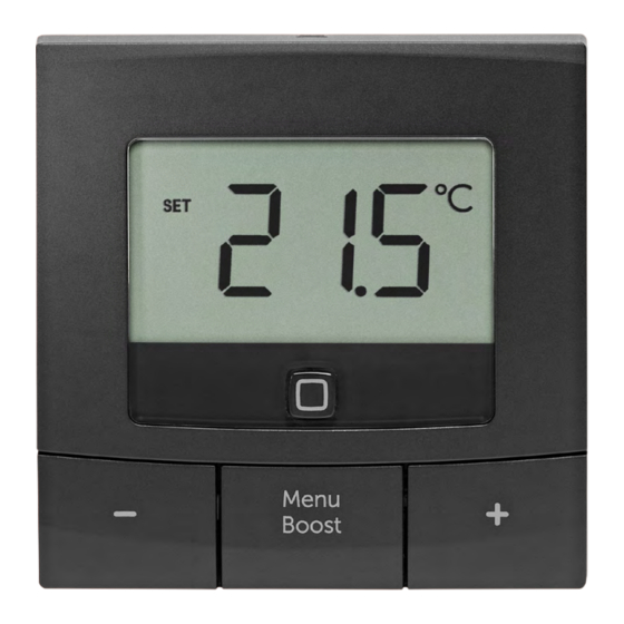
- Seite 6 Allgemeine Systeminformationen Displayübersicht: innerhalb des Homematic IP Systems im Zusammenspiel mit weiteren Kom- Soll-/Ist-Temperatur ponenten ergibt, entnehmen Sie bitte Luftfeuchtigkeit dem Homematic IP Anwenderhand- Fenster-auf-Symbol buch. Alle technischen Dokumente Batteriesymbol und Updates finden Sie stets aktuell Funkübertragung unter www.homematic-ip.com. Boost-Funktion Manueller Betrieb* 6 Inbetriebnahme Automatik Betrieb* Bitte lesen Sie diesen Abschnitt...
- Seite 7 Inbetriebnahme Halten Sie beim Anlernen einen 6.1.1 Anlernen an einen Mindestabstand von 50 cm zwi- Homematic IP Fußbodenheizungsaktor schen den Geräten ein. Wenn Sie den Wandthermostat an Sie können den Anlernvorgang einen Homematic IP Fußbodenhei- durch erneute kurze Betätigung zungsaktor anlernen möchten, müssen der Systemtaste (C) abbrechen.
- Seite 8 Inbetriebnahme • Drücken Sie die Systemtaste (C) • Drücken Sie für mind. 4 s auf die Systemtaste (C), um den Anlern- des Wandthermostats für mind. 4 s, um den Anlernmodus zu aktivieren. modus zu aktivieren. Die Geräte- Die Geräte-LED (C) blinkt orange. LED (C) beginnt orange zu blinken.
- Seite 9 Inbetriebnahme Richten Sie zunächst Ihren Sie können den Anlernmodus Homematic IP Access Point über manuell für weitere 3 Minuten die Homematic IP App ein, um starten, indem Sie die Systemtaste weitere Homematic IP Geräte im (C) kurz drücken. System nutzen zu können. Aus- führliche Informationen dazu finden Sie in der Bedienungsanlei- tung des Access Points.
- Seite 10 Inbetriebnahme Montage • Setzen Sie die Elektronikeinheit (A) in die Wandhalterung ein. Achten Bitte lesen Sie diesen Abschnitt Sie darauf, dass die Elektronikein- erst vollständig, bevor Sie mit der heit vollständig in die Wandhalte- Montage beginnen. rung einrastet. Bei der Montage im Wechselrahmen können Sie den Wandthermostat •...
- Seite 11 Inbetriebnahme • Drücken Sie den zusammengebau- • Bohren Sie die vorgezeichneten ten Wandthermostat mit der Rück- Löcher. seite an die gewünschte Position an die Wand. Abbildung 12 Bei Steinwänden verwenden Sie Abbildung 10 einen 5 mm Bohrer für die Dübel. Bei Holzwänden können Sie einen 6.3.2 Schraubmontage 1,5 mm Bohrer verwenden, um...
- Seite 12 Inbetriebnahme • Setzen Sie die Elektronikeinheit (A) Hinweis! Installation nur durch in die Wandhalterung ein. Achten Personen mit einschlägigen elekt- Sie darauf, dass die Elektronikein- rotechnischen Kenntnissen und heit vollständig in die Wandhalte- Erfahrungen!* rung einrastet. Durch eine unsachgemäße Installation gefährden Sie •...
- Seite 13 Konfigurationsmenü • Art des Versorgungsnetzes (TN- nächsten manuellen Änderung er- System, IT-System, TT-System) und halten. Um den manuellen Betrieb zu die daraus folgenden Anschluss- aktvieren, gehen Sie wie folgt vor: bedingungen (klassische Nullung, • Drücken Sie für ca. 2 s auf die Me- Schutzerdung, erforderliche Zu- nü-Taste (E), um das Konfigurati- satzmaßnahmen etc.).
- Seite 14 Konfigurationsmenü Urlaubsmodus deaktivieren, gehen Sie wie folgt vor: • Drücken Sie für ca. 2 s auf die Me- Der Urlaubsmodus kann genutzt wer- nü-Taste (E), um das Konfigurati- den, wenn für einen bestimmten Zeit- onsmenü zu öffnen. raum dauerhaft eine feste Temperatur gehalten werden soll (z.
- Seite 15 Konfigurationsmenü • Bestätigen Sie mit der Menü-Taste. • Wählen Sie über die Plus- oder Minus-Tasten die gewünschte Off- • Wählen Sie über die Plus- oder set-Temperatur aus und bestätigen Minus-Tasten das Jahr aus und be- Sie mit der Menü-Taste. stätigen Sie mit der Menü-Taste. •...
- Seite 16 Bedienung 9 Batterien wechseln abschnitt aus und bestätigen Sie mit der Menü-Taste. Erscheint das Symbol für leere Batteri- • Wiederholen Sie diesen Vorgang, en ( ) im Display bzw. in der App, tau- bis für den gesamten Zeitraum von schen Sie die verbrauchten Batterien 0:00 bis 23:59 Uhr Temperaturen gegen zwei neue Batterien des Typs hinterlegt sind.
- Seite 17 Fehlerbehebung 10.3 Duty Cycle Nach dem Einlegen der Batterien führt der Wandthermostat zunächst einen Der Duty Cycle beschreibt eine ge- Selbsttest für ca. 2 Sekunden durch. setzlich geregelte Begrenzung der Danach erfolgt die Initialisierung. Den Sendezeit von Geräten im 868-MHz- Abschluss bildet die Test-Anzeige: Bereich.
- Seite 18 Fehlerbehebung 10.4 Fehlercodes und Blinkfolgen Blinkcode Bedeutung Lösung Tauschen Sie die Batterien des Gerätes aus (s. „9 Bat- Batterie-Symbol ( Batteriespannung gering terien wechseln“ auf Seite 16). Kommunikationsstörung Prüfen Sie die Verbindung Antennen-Symbol zum Homematic IP Ac- zum Homematic IP Ac- blinkt ( ) cess Point/Fußbodenhei- cess Point/Fußbodenhei- zungsaktor...
- Seite 19 Wiederherstellung der Werkseinstellungen 11 Wiederherstellung der • Lassen Sie die Systemtaste wieder los. Werkseinstellungen Die Werksteinstellungen des Ge- rätes können wiederhergestellt werden. Dabei gehen alle Einstel- lungen verloren. Um die Werkseinstellungen des Wand- thermostats wiederherzustellen, gehen Sie wie folgt vor: •...
- Seite 20 Altgerät zu trennen und vor Ort eine wichtige Rolle. getrennt über die örtlichen Sammel- stellen zu entsorgen. Wir machen aus- Hiermit erklärt die eQ-3 AG, Maiburger drücklich darauf aufmerksam, dass Sie Str. 29, 26789 Leer, Deutschland, dass als Endnutzer eigenverantwortlich für der Funkanlagentyp Homematic IP...
- Seite 21 Technische Daten 15 Technische Daten Geräte-Kurzbezeichnung: HmIP-WTH-B-2, HmIP-WTH-B-A Versorgungsspannung: 2x 1,5 V LR6/Mignon/AA Stromaufnahme: 40 mA max. Batterielebensdauer: 5 Jahre (typ.) Schutzart: IP20 Verschmutzungsgrad: Umgebungstemperatur: 0 bis 50 °C Abmessungen (B x H x T): 85 x 85 x 22 mm Gewicht: 140 g (inkl.
- Seite 22 Installation and operating manual Table of contents Package contents..................24 Information about this manual ..............24 Hazard information ................... 24 Function and device overview ..............25 General system information ..............26 Start-up ......................26 Direct pairing ..................... 26 6.1.1 Pairing with a Homematic IP Floor Heating Actuator ....27 6.1.2 Pairing with other Homematic IP devices........28 Pairing to the Homematic IP Access Point ..........28...
- Seite 23 14 Disposal ......................39 15 Technical specifications ................40 Documentation © 2022 eQ-3 AG, Germany All rights reserved. Translation from the original version in German. This manual may not be reproduced in any format, either in whole or in part, nor may it be duplicated or edited by electronic, mechanical or chemical means, without the written consent of the publisher.
- Seite 24 Package contents Package contents Contact with batteries that are dead or damaged can cause skin Homematic IP Wandthermostat – irritation. Use protective gloves in basic this case. 1x Wandhalterung Do not open the device. It does 2x Doppelseitige Klebestreifen not contain any parts that can be 2x Schrauben 3,0 x 30 mm maintained by the user.
- Seite 25 Function and device overview Using the device for any purpose Device overview: other than that described in this (A) Electronic unit (thermostat) operating manual does not fall (B) Display within the scope of intended use (C) System button (pairing button and and will invalidate any warranty or LED) liability.
- Seite 26 General system information Display overview: with other components are described in the Homematic IP User Guide. All Setpoint/actual temperature current technical documents and up- Humidity dates are provided at Open window symbol www.homematic-ip.com. Battery symbol Radio transmission 6 Start-up Boost function Manual operation* Please read this entire section Automatic mode*...
- Seite 27 Start-up You can cancel the pairing proce- • Select the required channel of the dure by briefly pressing the sys- floor heating actuator and activate tem button (C) again. This will be the pairing mode using a long but- indicated by the device LED (C) ton press.
- Seite 28 Start-up 6.1.2 Pairing with other Pairing to the Homematic IP Homematic IP devices Access Point To connect the wall thermostat with You can connect the device either another Homematic IP device, the to the Homematic IP Access Point pairing mode of both devices has to be or the Central Control Unit CCU3.
- Seite 29 Start-up Mounting • Pairing mode remains activated for 3 minutes. Please read this entire section before starting to mount the de- You can manually start the pairing vice. mode for another 3 minutes by You can operate the wall thermostat pressing the system button (C) with shortly...
- Seite 30 Start-up 6.3.2 Screw mounting • Fix the adhesive strips on the back side of the mounting plate in the For mounting the wall thermostat by provided area. You should be able screws, please proceed as follows: to read the letters (“TOP”) on the •...
- Seite 31 Start-up • Use the supplied screws and plugs If the device is mounted to a to fasten the mounting plate to the flush-mounting box, there may be wall. no open conductor ends. If changes or works have to be made on the house installation (e.g.
- Seite 32 Configuration menu Manual operation equipment and, if necessary, per- sonal safety equipment; In manual mode, the temperature is • Evaluation of measuring results; controlled in accordance with the • Selection of electrical installation current temperature set via the push- material for safeguarding shut-off buttons (D + F).
- Seite 33 Configuration menu Holiday mode menu. • Confirm with the menu button. If you want to maintain a constant temperature for a certain period, e.g. • Use the plus button to select “On” during your holidays or a party, the to activate the operating lock or holiday mode can be used.
- Seite 34 Configuration menu with the menu button. Programming a heating profile • Select the desired hours using the In this menu item, you can create a plus or minus button and confirm heating profile with six heating and with the menu button. cooling phases (13 change settings) •...
- Seite 35 Operation 8 Operation (A) can easily be pulled out of the mounting plate. Take hold of the After pairing and mounting have been sides of the electronic unit and pull performed, simple operations are it from the mounting plate. available directly on the device: •...
- Seite 36 Troubleshooting 10 Troubleshooting 10.3 Duty Cycle The duty cycle is a legally regulated li- mit of the transmission time of devices 10.1 Low battery in the 868 MHz range. The aim of this Provided that the voltage value per- regulation is to safeguard the opera- mits it, the wall thermostat will remain tion of all devices working in the 868 ready for operation also if the battery...
- Seite 37 Troubleshooting 10.4 Error codes and flashing sequences Error and flashing codes Meaning Solution Replace the batteries of the device (see „9 Repla- Battery symbol ( ) Battery voltage too low cing batteries“ on page 35). Please check the Communication problem connection with the Antenna symbol with the Homematic IP...
- Seite 38 Restore factory settings 11 Restore factory settings • Press and hold down the system button (C) again for 4 seconds, un- The factory settings of the device til the LED lights up green. can be restored. If you do this, you will lose all your settings.
- Seite 39 Please also remember that you, the end user, are responsible for deleting eQ-3 AG, Maiburger Straße 29, 26789 personal data on any old electrical and Leer, Germany hereby declares that the electronic equipment before disposing radio equipment type Homematic IP...
- Seite 40 Technical specifications 15 Technical specifications Device short name: HmIP-WTH-B-2, HmIP-WTH-B-A Supply voltage: 2x 1.5 V LR6/mignon/AA Current consumption: 40 mA max. Battery life: 5 years (typ.) Degree of protection: IP20 Degree of pollution: Ambient temperature: 0 to 50 °C Dimensions (W x H x D): 85 x 85 x 22 mm Weight: 140 g (including batteries)
- Seite 41 Notice d‘installation et d‘emploi Table des matières Contenu de la livraison ................43 Remarques sur la notice ................43 Mises en garde .................... 43 Fonction et aperçu de l’appareil ............. 44 Informations générales sur le système ..........45 Mise en service ................... 45 Apprentissage direct ..................46 6.1.1 Apprentissage sur un Homematic IP Actionneur de chauffage par...
- Seite 42 14 Élimination ....................59 15 Caractéristiques techniques ..............60 Documentation © 2022 eQ-3 AG, Allemagne Tous droits réservés. Le présent manuel ne peut être reproduit, en totalité ou sous forme d’extraits, de manière quelconque sans l’accord écrit de l’éditeur, ni copié ou modifié par des procédés électroniques, mécaniques ou chimiques.
- Seite 43 Contenu de la livraison Contenu de la livraison Les piles usagées ou endomma- gées risquant de provoquer des Homematic IP Thermostat brûlures au contact de la peau, mural – basic portez des gants de protection le 1x Support mural cas échéant. 2x Bandes adhésives double face N’ouvrez pas l’appareil.
- Seite 44 Fonction et aperçu de l’appareil Nous ne pouvons être tenus res- cadre de rechange fourni, en vissant ponsables des dommages indi- ou en collant la plaque de montage rects occasionnés ! sur différents supports, tels que la ma- çonnerie, les meubles, les faïences ou L’appareil convient uniquement des vitres.
- Seite 45 Informations générales sur le système Aperçu de l’écran: cilement et individuellement avec un Smartphone à l’aide de l’application Température de consigne/ Homematic IP. Dans le manuel de réelle l’utilisateur Homematic IP, vous trou- Humidité de l’air verez l’étendue des fonctions du sys- Icône tème Homematic IP en association Symbole pile...
- Seite 46 Mise en service Apprentissage direct Si vous souhaitez ajouter un ther- mostat mural à un groupe Vous pouvez programmer d’appareils existant constitué d’un le Homematic IP Thermostat mu- thermostat de radiateur et d’un ral sur un Homematic IP Action- contact pour fenêtre et porte, neur de chauffage par le sol vous devez tout d’abord program- (HmIP-FALx-Cx,...
- Seite 47 Mise en service partiment à piles (G), en retirant le • Ouvrez, le cas échéant, le com- partiment à piles (G) en retirant le support mural au moyen d’un tour- support mural au moyen d’un tour- nevis plat (v. figure). nevis plat.
- Seite 48 Mise en service Programmation sur le • Ouvrez, le cas échéant, le com- Homematic IP Access Point partiment à piles (G) en retirant le support mural au moyen d’un tour- Vous pouvez programmer nevis plat (v. figure). l’appareil sur le Homematic IP Access Point ou sur la centrale •...
- Seite 49 Mise en service peut désormais être utilisé. nique s’encliquète complètement dans le support mural. • Si la LED s’allume est rouge, re- commencez une nouvelle fois. • Choisissez la solution souhaitée pour votre appareil. • Dans l’appli, affectez l’appareil à une pièce et donnez un nom à...
- Seite 50 Mise en service • Appuyez ensuite le thermostat • Percez les trous prédéfinis. Abb 11 mural assemblé avec le dos sur la position souhaitée au mur. Figure 12 Sur les murs en maçonnerie, utili- sez un foret de 5 mm pour les chevilles.
- Seite 51 Mise en service 6.3.3 Montage sur un boîtier encastré Une pose non conforme peut égale- ment entraîner des dommages ma- Vous pouvez monter le thermos- tériels lourds (par ex. incendie). Votre tat mural à l’aide des trous pour les responsabilité risque d’être engagée en vis sur un boîtier encastré/une boîte cas de dommages corporels et matéri- d’installation.
- Seite 52 Menu de configuration Menu de configuration moins (D + F). • Confirmez avec la touche Menu. Lorsque vous utilisez le thermostat mural sans Homematic IP Access Point, Pour confirmer l’opération, le sym- vous pouvez sélectionner les modes bole clignote brièvement deux fois et suivants via le menu de configuration l’appareil passe en mode manuel.
- Seite 53 Menu de configuration • Appuyez pendant environ 2 s sur lage de commande ou « OFF » via la touche Menu (E)pour ouvrir le la touche moins pour désactiver menu de configuration. le verrouillage de commande, puis confirmez avec la touche Menu. •...
- Seite 54 Menu de configuration • Sélectionnez les heures via les tou- Programmation d’un profil de chauffage ches plus ou moins et confirmez avec la touche Menu. Cette option de menu vous permet de • Sélectionnez les minutes via les réaliser un profil de chauffage avec six touches plus ou moins et confir- phases de chauffage et de diminution mez avec la touche Menu.
- Seite 55 Utilisation 8 Utilisation Pour remplacer les piles de l’appareil, procédez comme suit : Après la programmation et le montage, • À l’état monté, il est facile de reti- diverses fonctions de commande sim- rer le module électronique (A) du ples sont à votre disposition : support mural.
- Seite 56 Correction des erreurs 10 Correction des erreurs 10.3 Duty Cycle Le Duty Cycle décrit une limitati- on réglementée par la loi du temps 10.1 Pile faible d’émission des appareils dans une Si la valeur de la tension le permet, le plage de fréquences de 868 MHz.
- Seite 57 Correction des erreurs 10.4 Codes d’erreur et séquences de clignotement Codes d’erreur et codes Signification Solution de clignotement Remplacez les piles de l’appareil (v. „ 9 Remplace- Symbole pile ( ) Tension des piles faible ment des piles „ à la page 55).
- Seite 58 Restauration des réglages d’usine 11 Restauration des réglages • Appuyez de nouveau sur la tou- che système pendant 4 secondes, d’usine jusqu’à ce que la LED (C) s’allume Les réglages d’usine de l’appareil en vert. peuvent être rétablis. Dans ce cadre, tous les réglages antérieurs sont perdus.
- Seite 59 à un point de important. collecte en vue de leur traitement par les centres de recyclage locaux. Par la présente, eQ-3 AG, basée à Mai- Nous attirons expressément vot- burger Str. 29, 26789 Leer, en Allema- re attention sur le fait, qu’en tant gne, déclare que l’équipement radioé-...
- Seite 60 Caractéristiques techniques 15 Caractéristiques techniques Désignation abrégée de l’appareil : HmIP-WTH-B-2, HmIP-WTH-B-A Tension d’alimentation : 2x 1,5 V LR6/Mignon/AA Courant absorbé : 40 mA max. Durée de vie des piles : 5 ans (typiquement) Type de protection : IP20 Degré de contamination : Température ambiante : de 0 à 50 °C Dimensions (l x H x P) : 85 x 85 x 22 mm Poids :...
- Seite 61 Manual de instalación y uso Índice Volumen de suministro ................63 Advertencias sobre estas instrucciones ..........63 Advertencias de peligro ................63 Funciones y esquema del dispositivo ............. 64 Información general del sistema ............65 Puesta en servicio ..................65 Conexión directa....................66 6.1.1 Conexión a un Homematic IP Actuador de suelo radiante ..66...
- Seite 62 14 Eliminación ....................79 15 Datos técnicos .................... 80 Documentación © 2022 eQ-3 AG, Alemania Todos los derechos reservados. Queda prohibida la reproducción total o parcial de estas instrucciones en todas las formas posibles o utilizando procedimientos electrónicos, mecánicos o químicos, así como su divulgación, sin el consentimiento por escrito del editor.
- Seite 63 Volumen de suministro Volumen de suministro Las pilas gastadas o dañadas pue- den causar quemaduras en con- Homematic IP Termostato de pa- tacto con la piel. En estos casos, red – basic utilice unos guantes de protecci- 1x Soporte para pared ón adecuados.
- Seite 64 Funciones y esquema del dispositivo El dispositivo solo es apto para Esquema del dispositivo: entornos domésticos. (A) Unidad electrónica (termostato) (B) Pantalla Todo uso distinto del indicado en (C) Botón del sistema (botón de cone- estas instrucciones se considera xión y LED) incorrecto y conlleva la anulación (D) Botón de menos de la garantía y la responsabilidad.
- Seite 65 Información general del sistema Esquema de la pantalla: 5 Información general del Temperatura nominal y real sistema Humedad del aire Este dispositivo forma parte del siste- Símbolo de ventana abierta ma de climatización de Homematic IP Símbolo de batería y se comunica mediante el protocolo Transmisión inalámbrica de radio de Homematic IP.
- Seite 66 Puesta en servicio Conexión directa Si desea agregar un termostato de pared a un grupo ya existente, for- Homematic IP Termostato de mado por termostato de radiador pared puede ser conectado a un y contacto para ventana y puerta, Homematic IP Actuador del suelo primero tiene que conectar el radiante (HmIP-FALx-Cx, termostato de pared al termostato...
- Seite 67 Puesta en servicio 6.1.2 Conexión a otros dispositivos • Dado el caso, abra el comparti- Homematic IP mento de las pilas (G), soltando para ello el soporte de pared con Para conectar el termostato de pared a un destornillador plano. otro dispositivo Homematic IP es ne- cesario activar el modo de conexión en los dos dispositivos.
- Seite 68 Puesta en servicio Conexión a Homematic IP • El modo de conexión está activo Access Point durante 3 minutos. También se puede conectar el dispositivo a Homematic IP Ac- Puede activar el modo de conexi- cess Point o a la CCU3 central. ón manualmente para 3 minutos Para más información al respecto, con una pulsación corta del botón...
- Seite 69 Puesta en servicio • Inserte la unidad electrónica (A) en • Asigne una sala al dispositivo en la aplicación e introduzca un nombre el soporte de la pared. Compruebe para el dispositivo. que la unidad electrónica esté bien encajada en el soporte de la pared. Montaje Por favor, lea íntegramente este capítulo antes de realizar el mon-...
- Seite 70 Puesta en servicio • Presione el termostato ya ensam- • Taladre los orificios marcados. blado con la parte trasera contra la pared en el punto deseado. Figura 11 En paredes de piedra debe utilizar una broca de 5 mm para los tacos. En paredes de madera puede Figura 9 utilizar una broca de 1,5 mm para...
- Seite 71 Puesta en servicio 6.3.3 Montaje en cajetín empotrado caso de lesiones físicas y daños mate- riales. También se puede realizar la instalaci- ón del termostato de pared con ayu- da de un cajetín empotrado o caja de ¡Solicite los servicios de un electricista! instalación.
- Seite 72 Menú de configuración Menú de configuración Como confirmación, el símbolo par- padea dos veces cortas y el dispositivo Si utiliza el termostato de pared sin cambia al modo manual. Homematic IP Access Point, tras la instalación puede acceder al menú de Modo automático configuración directamente en el dis- El cambio de modo manual a...
- Seite 73 Menú de configuración o menos (D + F) y confirme con el Como confirmación, el parámetro botón de menú. elegido parpadea dos veces cortas y el dispositivo cambia de nuevo a la indi- • Introduzca con los botones de más cación fija. o menos la hora hasta la que deba estar activo el modo vacaciones y Cuando el bloqueo está...
- Seite 74 Menú de configuración de más o menos y confirme con el Programación de un perfil de calefacción botón de menú. En este menú puede crear un perfil de calefacción con seis fases de activaci- Como confirmación, la hora parpadea ón y desactivación (13 puntos de con- dos veces cortas y el dispositivo cam- mutación) según sus deseos persona- bia de nuevo a la indicación fija.
- Seite 75 Manejo 9 Cambio de pilas Como confirmación, la hora parpadea dos veces cortas y el dispositivo cam- El símbolo de batería descargada ( ) bia de nuevo a la indicación fija. en la pantalla o en la aplicación indi- ca que es necesario cambiar las pilas 8 Manejo gastadas por dos pilas nuevas del tipo LR6/Mignon/AA.
- Seite 76 Reparación de fallos 10.3 Duty Cycle Tras un cambio de pilas el dispositivo ejecuta en primer lugar una prueba Duty Cycle describe una limitación del automática durante unos 2 segundos. tiempo de transmisión regulada por ley A continuación tiene lugar la iniciali- para dispositivos en la banda de 868 zación.
- Seite 77 Reparación de fallos 10.4 Códigos de errores y secuencias intermitentes Código de errores y se- Significado Solución cuencia intermitente Cambie las pilas del dis- Símbolo de la batería ( ) Tensión de la pila baja positivo (v. „9 Cambio de pilas“...
- Seite 78 Restablecimiento de la configuración de fábrica 11 Restablecimiento de la • Pulse de nuevo el botón del sis- tema durante 4 seg. hasta que se configuración de fábrica encienda el LED (C) verde. Se puede restablecer la configura- ción de fábrica del dispositivo. Al hacerlo se pierden todos los ajus- tes.
- Seite 79 AG, Maiburger Str. 29, 26789 desecharlos por separado a través del Leer, Alemania, declara que el tipo de punto de recogida local.
- Seite 80 Datos técnicos 15 Datos técnicos Nombre abreviado del dispositivo: HmIP-WTH-B-2, HmIP-WTH-B-A Tensión de alimentación: 2 pilas LR6/Mignon/AA, 1,5 V Consumo de corriente: máx. 40 mA Duración de las pilas: 5 años (típ.) Tipo de protección: IP20 Grado de suciedad: Temperatura ambiente: de 0 a 50 °C Dimensiones (A x H x P): 85 x 85 x 22 mm...
- Seite 81 Istruzioni per l‘installazione e l‘uso Indice Fornitura ...................... 83 Indicazioni su queste istruzioni ............... 83 Indicazioni di pericolo................83 Funzioni e vista d’insieme dell’apparecchio Informazioni generali sul sistema ............85 Messa in funzione ..................85 Accoppiamento diretto..................86 6.1.1 Accoppiamento con un attuatore per riscaldamento a pavimento Homematic IP ..................86 6.1.2 Accoppiamento con altri apparecchi Homematic IP ....87...
- Seite 82 14 Smaltimento ....................99 15 Dati Tecnici ....................100 Documentazione © 2022 eQ-3 AG, Germania Tutti i diritti riservati. Senza l’approvazione scritta del produttore è vietata la riproduzione di questo manuale o di sue parti in qualsiasi forma o la sua duplicazione o modifica con l’utilizzo di processi elettronici, meccanici o chimici.
- Seite 83 Fornitura Fornitura un calore eccessivo. Non mettere in cortocircuito le batterie. Rischio Homematic IP Termostato a di esplosione! parete – basic Le batterie danneggiate o che 1x Supporto a parete perdono liquido possono provo- 2x Strisce bi-adesive care ustioni in caso di contatto 2x Viti 3,0 x 30 mm con la pelle, pertanto utilizzare 2x Tasselli 5 mm...
- Seite 84 Funzioni e vista d’insieme dell’apparecchio simili decade il diritto alla garan- one, la piastra di montaggio si avvita o zia! Si declina qualsiasi responsa- si incolla sui più diversi substrati, come bilità per danni indiretti! muratura, mobili, piastrelle o vetro, così...
- Seite 85 Informazioni generali sul sistema Vista d’insieme del display: possono essere configurati comoda- mente e singolarmente dallo smart- Temperatura programmata/ phone tramite l’app Homematic IP. Per effettiva conoscere la gamma di funzioni che Umidità dell’aria si può utilizzare all’interno del siste- Icona “Finestra aperta” ma Homematic IP abbinato ad altri Icona della batteria componenti, consultare il Manuale...
- Seite 86 Messa in funzione Accoppiamento diretto Volendo aggiungere un termosta- to a parete a un gruppo di appa- Il termostato a parete recchi pre-esistente, composto da Homematic IP può essere accop- termostato per radiatori e contat- piato con un attuatore per ris- to per finestre e porta, si deve caldamento a pavimento accoppiare prima il termostato a...
- Seite 87 Messa in funzione 6.1.2 Accoppiamento con altri • Se necessario aprire il vano batterie apparecchi Homematic IP (G) allentando il supporto a parete con un cacciavite a punta piatta. Per accoppiare il termostato a pa- rete con un altro apparecchio Homematic IP è necessario portare entrambi gli apparecchi in modalità...
- Seite 88 Messa in funzione (G) allentando il supporto a parete • Per confermare che la procedura di accoppiamento è andata a buon con un cacciavite a punta piatta fine la luce del LED diventa verde. (v. figura). • Tirare la linguetta d’isolamento Accoppiamento con l’Access dal vano batterie del termostato a Point Homematic IP...
- Seite 89 Messa in funzione • Inserire la centralina elettronica (A) • Selezionare la soluzione desiderata per il proprio dispositivo. nel supporto a parete. Accertarsi che la centralina elettronica si in- • Assegnare il dispositivo a una stan- serisca fino a bloccarsi del tutto za all’interno dell’app e assegnare all’interno del supporto a parete.
- Seite 90 Messa in funzione • Spingere il termostato a parete così • Eseguire i fori precedentemente assemblato con il lato posteriore segnati sulla parete verso la posizione prescelta sulla parete Figura 12 Nelle pareti in pietra utilizzare una Figura 10 punta da 5 mm per i tasselli. Nelle pareti di legno si può...
- Seite 91 Messa in funzione 6.3.3 Montaggio su una presa sotto ni materiali, ad es. dovuti a un incen- intonaco dio. In caso di danni a persone o cose Il termostato a parete può essere mon- si rischia l’attribuzione di responsabilità personale. tato su una scatola di installazione a in- casso/presa sotto intonaco utilizzando i fori filettati.
- Seite 92 Menu di configurazione Menu di configurazione • Confermare con il tasto Menu. Se il termostato a parete viene utilizza- L’icona lampeggia brevemente due to senza l’Access Point Homematic IP, volte per confermare l’operazione e per adattare il dispositivo alle esigenze l’apparecchio passa alla modalità ma- personali una volta messo in funzione, nuale.
- Seite 93 Menu di configurazione dere nel modo seguente: “On” e attivare il Blocco comandi oppure premere il tasto Meno per • Premere per ca. 2 secondi il tasto selezionare “OFF” e disattivare il Menu (E) per aprire il menu di con- Blocco comandi e confermare con figurazione.
- Seite 94 Menu di configurazione • Selezionare le ore con i tasti Più l‘operazione e l’apparecchio torna alla o Meno e confermare con il tasto schermata standard. Menu. Programmazione di un profilo di • Selezionare i minuti con i tasti Più riscaldamento o Meno e confermare con il tasto In questa voce del menu si può...
- Seite 95 9 Sostituzione delle batterie L’orario lampeggia due volte breve- mente per confermare l’operazione Se sul display o nell’app compare e l’apparecchio torna alla schermata l’icona di batterie scariche ( ), sostitui- standard. re le batterie esauste con due batterie nuove tipo LR6/mignon/AA. Fare at- 8 Uso tenzione a posizionare i poli nel senso corretto.
- Seite 96 Risoluzione dei guasti Una volta inserite le batterie blocco meccanico, ecc.) oppure l’apparecchio esegue per prima • ricevitore difettoso. cosa un test autodiagnostico per ca. 2 secondi. Subito dopo esegue 10.3 Duty Cycle l’inizializzazione. La visualizzazione del Il ciclo di lavoro descrive una limita- test rappresenta la conclusione: luce zione regolamentata dalla legge del arancione e verde.
- Seite 97 Risoluzione dei guasti 10.4 Codici di errore e sequenze di spie lampeggianti Codice di errore e di lam- Significato Soluzione peggio Sostituire le batterie Tensione della batteria dell’apparecchio (v. „9 So- Icona della batteria ( ) scarsa stituzione delle batterie“ a pag.
- Seite 98 Ripristino delle impostazioni di fabbrica 11 Ripristino delle impostazioni di fabbrica L’utente può ripristinare le impos- tazioni di fabbrica dell’apparecchio. In questo caso tutte le impostazioni andranno perdute. Per ripristinare le impostazioni di fa- Figura 18 bbrica dell’apparecchio procedere nel •...
- Seite 99 Ricordiamo espressamente che come Con la presente, eQ-3 AG, con sede in utente finale siate responsabili perso- Maiburger Str. 29, 26789 Leer, Germa- nalmente della cancellazione dei dati nia, dichiara che l’apparecchio radio personali sugli apparecchi elettrici ed Homematic IP modello...
- Seite 100 Dati Tecnici 15 Dati Tecnici Sigla dell’apparecchio: HmIP-WTH-B-2, HmIP-WTH-B-A Tensione di alimentazione: 2 batterie LR6/mignon/AA da 1,5 V Corrente assorbita: 40 mA max. Durata batterie: 5 anni (tip.) Grado di protezione: IP20 Grado di contaminazione: Temperatura ambiente: tra 0 e 50 °C Dimensioni (L x A x P): 85 x 85 x 22 mm Peso:...
- Seite 101 Installatie- en bedieningshandleiding Inhoudsopgave Leveringsomvang ..................103 Instructies bij deze handleiding ............103 Gevarenaanduidingen ................103 Werking en overzicht van het apparaat ..........104 Algemene systeeminformatie ..............105 Inbedrijfstelling ..................105 Direct aanleren ....................106 6.1.1 Aanleren aan een Homematic IP Vloerverwarmingsactor ..106 6.1.2 Aanleren aan andere Homematic IP apparaten ......107 Aanleren aan het Homematic IP Access Point ..........108...
- Seite 102 14 Verwijdering als afval ................119 15 Technische gegevens ................120 Documentatie © 2022 eQ-3 AG, Duitsland Alle rechten voorbehouden. Zonder schriftelijke toestemming van de uitgever mogen deze handleiding of fragmen- ten ervan op geen enkele manier worden gereproduceerd of met behulp van elektronische, mechanische of chemi- sche middelen worden verveelvoudigd of verwerkt.
- Seite 103 Leveringsomvang Leveringsomvang Uitgelopen of beschadigde batte- rijen kunnen bij aanraking met de Homematic IP Wandthermo- huid brandwonden veroorzaken; staat – basic gebruik daarom in dergelijk geval 1x Wandhouder geschikte veiligheidshandschoe- 2x Dubbelzijdige plakstrips nen. 2x Schroeven 3,0 x 30 mm Open het apparaat niet. Het bevat 2x Pluggen 5 mm geen onderdelen die door de 2x 1,5V-batterij LR6/mignon/AA...
- Seite 104 Werking en overzicht van het apparaat Het apparaat is uitsluitend geschi- Overzicht van het apparaat: kt voor gebruik in woonruimten (A) Elektronische unit (thermostaat) en soortgelijke omgevingen. (B) Display (C) Systeemtoets (aanleertoets en led) Elk ander gebruik dan wat in deze (D) Min-toets handleiding beschreven wordt, is (E) Menu-/boosttoets...
- Seite 105 Algemene systeeminformatie Overzicht van het display: 5 Algemene Instel-/werkelijke tempera- systeeminformatie tuur Dit apparaat is een onderdeel van Luchtvochtigheid Homematic IP en communiceert via Raam-open-symbool het Homematic IP Zendprotocol. Alle Batterijsymbool apparaten van de binnenklimaatop- Draadloze overdracht lossing kunnen comfortabel en indi- Boostfunctie vidueel via een smartphone met de Handmatig bedrijf*...
- Seite 106 Inbedrijfstelling Direct aanleren Als u aan een bestaande appara- tengroep uit radiatorthermostaat U kunt de Homematic IP Wand- en raam- en deurcontact een thermostaat aan een wandthermostaat wilt toevoegen, Homematic IP Vloerverwar- moet u eerst de wandthermostaat mingsactor aan de radiatorthermostaat aanle- (HmIP- (HmIP-FALx-Cx, ren.
- Seite 107 Inbedrijfstelling 6.1.2 Aanleren aan andere • Open zo nodig het batterijvakje Homematic IP apparaten (G) door de wandhouder met een sleufkopschroevendraaier los te Om de wandthermostaat op een ander draaien. Homematic IP apparaat aan te leren, moeten beide apparaten naar de aan- leermodus worden geschakeld.
- Seite 108 Inbedrijfstelling Aanleren aan het Homematic IP draaien (zie afbeelding). Access Point • Trek de isolatiestrip uit het batterij- U kunt het apparaat op het vakje van de wandthermostaat. Homematic IP Access Point of op • De aanleermodus is 3 minuten ac- de centrale CCU3 aanleren. Voor tief.
- Seite 109 Inbedrijfstelling Montage • Bevestig de plakstrips op de ach- terzijde van de wandhouder in de Lees dit hoofdstuk volledig door, daarvoor bestemde markeringen. voordat u met de montage begint. Zorg ervoor dat de tekst (‘TOP’) op U kunt de wandthermostaat de achterzijde leesbaar blijft.
- Seite 110 Inbedrijfstelling 6.3.2 Montage met schroeven • Monteer de wandhouder door indraaien van de bijgeleverde plug- Ga als volgt te werk om de wandther- gen en schroeven. mostaat met de schroeven te monte- ren: • Kies een geschikte montageplaats. Waarborg dat op de geselecteerde positie geen leidingen in de wand lopen! •...
- Seite 111 Configuratiemenu In de inbouwdoos mogen zich kortsluiten; aangrenzende onder- geen open kabeleinden bevinden. delen die onder spanning staan, afdekken of afsluiten; Als voor de montage of installatie • selecteren van het geschikte ge- van het apparaat wijzigingen of reedschap, de meettoestellen en werkzaamheden aan de huisins- eventuele persoonlijke bescher- tallatie (bijv.
- Seite 112 Configuratiemenu Door lang op de Menu-toets (E) te tige wijzigingen blijven tot de volgende drukken schakelt u terug naar het schakeltijd actief. Daarna wordt het voorafgaande niveau. Indien lan- ingestelde verwarmingsprofiel weer ger dan 1 minuut geen toets aan geactiveerd. Ga als volgt te werk om het apparaat wordt ingedrukt, het automatische bedrijf te activeren: wordt het menu automatisch...
- Seite 113 Configuratiemenu zijn en bevestig uw invoer met de • Selecteer de minuten behulp van Menu-toets. de plus- en min-toetsen en beves- tig uw keuze met de Menu-toets. • Voer met behulp van de plus- en min-toetsen de gewenste tempe- ratuur in voor de tijd van afwezig- Ter bevestiging knippert de selectie heid en bevestig uw invoer met de twee keer kort en het apparaat schakelt...
- Seite 114 Configuratiemenu de plus- en min-toetsen en beves- tuur twee keer kort en het apparaat tig uw keuze met de Menu-toets. schakelt terug naar de standaardweer- gave. • Selecteer de uren met behulp van de plus- en min-toetsen en beves- Programmering van een tig uw keuze met de Menu-toets.
- Seite 115 Bediening 9 Batterijen vervangen Ter bevestiging knippert de tijd twee keer kort en het apparaat schakelt Als het symbool voor lege batterijen terug naar de standaardweergave. ( ) op het display of in de app ver- schijnt, dient u de verbruikte batterijen 8 Bediening te vervangen door twee nieuwe batte- rijen van het type LR6/mignon/AA.
- Seite 116 Storingen oplossen 10.3 Duty Cycle Na het plaatsen van de batterijen voert het apparaat gedurende ca. 2 secon- De duty cycle beschrijft een wettelijk den een zelftest uit. Daarna volgt de geregelde begrenzing van de zendtijd initialisatie. Tot slot verschijnt de test- van apparaten in het 868MHz-bereik.
- Seite 117 Storingen oplossen 10.4 Foutcodes en knipperreeksen Fout- en knippercode Betekenis Oplossing Vervang de batterij van het apparaat (zie ‚9 Batte- Batterijsymbool ( ) Batterijspanning gering rijen vervangen‘ op pagina 115). Communicatiestoring Controleer de verbinding Antennesymbool naar het Homematic IP naar het Homematic IP knippert ( ) Access Point of het aan- Access Point of de aange-...
- Seite 118 Herstellen van de fabrieksinstellingen 11 Herstellen van de • Houd de systeemtoets opnieuw 4 sec. ingedrukt tot de led (C) groen fabrieksinstellingen oplicht. De fabrieksinstellingen van het apparaat kunnen worden hersteld. Hierbij gaan alle instellingen ver- loren. Om de fabrieksinstellingen van het apparaat te herstellen, gaat u als volgt te werk: •...
- Seite 119 Hierbij verklaart eQ-3 AG, Maiburger Wij wijzen u er nadrukkelijk op dat u als Str. 29, 26789 Leer, Duitsland, dat het eindgebruiker verantwoordelijk bent draadloze apparaattype Homematic IP...
- Seite 120 Technische gegevens 15 Technische gegevens Apparaatcode: HmIP-WTH-B-2, HmIP-WTH-B-A Voedingsspanning: 2x 1,5 V LR6/mignon/AA Stroomopname: 40 mA max. Levensduur batterijen: 5 jaar (typ.) Beschermingsgraad: IP20 Verontreinigingsgraad: Omgevingstemperatuur: 0 tot 50 °C Afmetingen (b x h x d): 85 x 85 x 22 mm Gewicht: 140 g (incl.
- Seite 121 Kostenloser Download der Homematic IP App! Free download of the Homematic IP app! Bevollmächtigter des Herstellers: Manufacturer’s authorised representative: eQ-3 AG Maiburger Straße 29 26789 Leer / GERMANY www.eQ-3.de...