Seite 1
One stage operation Funcionamiento a 1 llama CODICE - CODE MODELLO - MODELL TIPO - TYP CÓDIGO MODEL - MODELO TYPE 3761112 - 3761158 911 T1 3761212 - 3761258 912 T1 3761312 - 3761316 913 T1 3761358 3761412 - 3761416...
Seite 2
55,9 - 172 kW 914 T1 94,6 - 215 kW Dichiarazione SVGW RIELLO S.p.A. dichiara che i bruciatori di gas ad aria soffiata modello BS1, BS2, BS3 e BS4 sono conformi alle seguenti direttive e prescrizioni tecniche: SSIGA Direttiva Gas G1...
DESCRIZIONE DEL BRUCIATORE Bruciatore di gas con funzionamento monostadio. Il bruciatore risponde al grado di protezione IP X0D (IP 40) secondo EN 60529. Marcatura CE secondo Direttiva Gas 2009/142/CEE; PIN 0085AQ0409. Conforme alle Direttive: CEM 2004/108/CE, Bassa Tensione 2006/95/CE e Macchine 2006/42/CEE. ...
CAMPI DI LAVORO 912T1 911T1 D8829 kcal/h 10.000 20.000 30.000 40.000 50.000 60.000 70.000 80.000 Potenza termica 914T1 913T1 D8830 50.000 100.000 200.000 250.000 kcal/h Potenza termica Nel modello BS4 tipo 914T1, per garantire il funzionamento con una potenzialità da 220 250 kW, togliere il fonoassorbente pretranciato per liberare le feritoie addizionali di ingresso d’aria sul cofano.
CORRELAZIONE TRA PRESSIONE DEL GAS E POTENZIALITÀ Per avere la massima potenzialità occorrono 9,3 mbar, relativamente al modello 912T1, misurati al manicotto (M2, vedi cap. 3.6, pag. 7) con camera di combustione a 0 mbar e gas G20 – Pci = 10 kWh/m (8.570 kcal/m D8933 150.000...
FISSAGGIO ALLA CALDAIA Per installare il bruciatore alla caldaia è necessario effettuare le seguenti operazioni: Allargare, se necessario, i fori dello schermo isolante (3, fig. 3). Fissare alla portina della caldaia (1) la flangia (5) mediante le quattro viti (4) e (se necessario) i dadi (2) interponendo lo schermo isolante (3) ma tenendo allentata una delle due viti superiori (4), (vedi fig.
RAMPA GAS, (secondo EN 676) La rampa gas viene fornita a parte e per la sua regolazione vedere le istruzioni che l’accompagnano. RAMPA GAS ATTACCHI BRUCIATORE IMPIEGO ABBINABILE TIPO CODICE INGRESSO USCITA MBC 65 DLE 3970570 Rp 1 / 2 Flangia 1 Gas naturale e GPL MBDLE 405 B01...
COLLEGAMENTI ELETTRICI LEGENDA – Condensatore CN1 – Connettore sonda – Elettrodo – Contaore MV – Motore PA – Pressostato aria PG – Pressostato gas minima RS – Reset remoto SO – Sonda ionizzazione – Spia blocco (230V - 0,5 A max) T6A –...
FUNZIONAMENTO REGOLAZIONE DELLA COM- BUSTIONE In conformità con la Direttiva Rendimento 92/42/CEE, l’applicazione del bruciatore alla caldaia, la regolazione e il collaudo, devono essere eseguiti nell’osservanza del manuale d’istruzione della caldaia stessa, compreso il controllo della concentrazione di CO e CO nei fumi, della loro temperatura e di quella media dell’acqua della caldaia.
ATTENZIONE Avvitare le viti (7) (senza bloccarle) fino a battuta; quindi bloccarle con una coppia di serraggio di 3 - 4 Nm. Controllare che, durante il funzionamento, non si verifichino perdite di gas dalle sedi delle viti. Qualora accidentalmente si allentasse la presa di pressione (11) si raccomanda il corretto fissaggio ass- icurandosi che il foro (F) posto nella parte interna del gruppo testa (1) sia rivolto verso il basso.
PROGRAMMA DI AVVIAMENTO Normale Blocco per mancata accensione Termostato Motore Trasf. d’accensione Valvola Fiamma Blocco D5007 40s min. 3s max. 40s min. 3s max. Segnalato dalla spia sull’apparecchiatura di comando e controllo (4, fig. 1, pag. 2). 4.7 FUNZIONE DI RICICLO L’apparecchiatura permette il riciclo, ossia la ripetizione completa del programma di avviamento, per un massimo di 3 tentativi nel caso in cui la fiamma si spegne in funzionamento.
MANUTENZIONE Prima di effettuare qualsiasi operazione di pulizia o controllo, togliere alimentazione elettrica al bruci- atore agendo sull’interruttore generale dell’impianto e chiudere la valvola d’intercettazione del gas. Il bruciatore richiede una manutenzione periodica, che deve essere eseguita da personale abilitato e in con- formità...
SEGNALE CAUSA PROBABILE Pressostato aria di minima non chiude o è già chiuso prima della chiusura del termostato limite: 3 lampeggi – guasto al pressostato aria; – pressostato aria non regolato; Luce presente in camera prima dell’accensione e allo spegnimento del bruciatore: 4 lampeggi –...
Seite 16
ANOMALIE POSSIBILE CAUSA RIMEDIO È invertito il collegamento Provvedere ad un loro scambio. fase-neutro. Manca o è inefficace il collegamento di bruciatore esegue Provvedere a renderlo efficiente. terra. normalmente il ciclo di preventilazione ed ac- Verificare la corretta posizione ed even- La sonda di ionizzazione è...
6.2 ANOMALIE IN FUNZIONAMENTO ANOMALIA POSSIBILE CAUSA RIMEDIO Verificare la corretta posizione ed even- tualmente aggiustarla secondo quanto indicato in questo manuale. Sonda a massa. Provvedere alla pulizia o la sostituzione della sonda di ionizzazione. I l b r u c i a t o r e v a i n Verificare la pressione del gas in rete e/o blocco in funziona- Sparizione della fiamma per 4 volte.
Seite 18
54 mg/kWh Kontrollorganismus: TÜV SÜD Industrie Service GmbH Ridlerstrase, 65 80339 Munchen DEUTSCHLAND Erklärung des Herstellers Die Firma RIELLO S.p.A. erklärt, dass die folgenden Produkte die vom deutschen Standard "1. BImSchV Fassung 26.01.2010” vorgeschriebenen NOx-Grenzwerte einhalten. Produkt Modell Leistung Gas-Gebläsebrenner...
Seite 19
INHALT BESCHREIBUNG DES BRENNERS ..........1.1 Mitgeliefertes Zubehör.
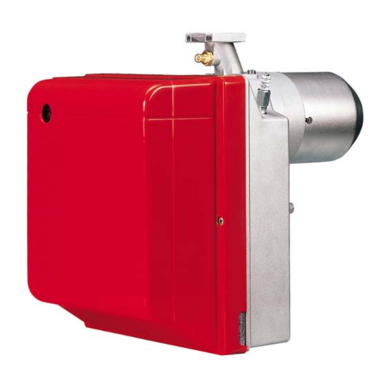
BESCHREIBUNG DES BRENNERS Gasbrenner mit einstufigem Betrieb. Der Brenner entspricht dem Schutzart IP X0D (IP 40) gemäß EN 60529. CE Kennzeichnung gemäß der Gasgeräterichtlinie 2009/142/EWG; PIN 0085AQ0409. Gemäß Richtlinien: EMV 2004/108/EG, Niederspannungsrichtlinie 2006/95/EG und Maschinenrichtlinie 2006/42/EWG. Gasstrecke gemäß der Euronorm EN 676. ...
ARBEITSFELDER 912T1 911T1 D8829 10.000 20.000 30.000 40.000 50.000 60.000 70.000 80.000 kcal/h Brennerleistung 914T1 913T1 D8830 50.000 100.000 200.000 250.000 kcal/h Brennerleistung In dem Modell BS4 Typ 914T1, um den Betrieb für eine Leistung vom 250 kW zu gewähren, die geschnittene Gerauschdämmung weg- nehmen, so werden die zusätzlichen Schlitze des Lufteingangs auf der Verkleidung frei gemacht.
VOM GASDRUCK AM BRENNERKOPF ABHÄNGIGE BRENNERLEISTUNG Bei einem an dem Verbindungsrohr (M2, siehe Kap. 3.6, Seite 7) gemessenen Druck von 9,3 mbar, hin- sichtlich des Modells 912T1, mit einem feuerraumseitigen Druck von 0 mbar und mit Gas G20 - unterer Heizwert = 10 kWh/m (8.570 kcal/m ), erreicht man die Höchstleistung.
3.2 BRENNERMONTAGE Zur Installation des Brenners am Heizkessel sind folgende Vorgänge auszuführen: Falls erforderlich, die Bohrungen der Isolierdichtung (3, Abb. 3) erweitern. Mit den Schrauben (4) (falls erforderlich) den Muttern (2) an der Kesseltür (1) den Flansch (5) mit Isoli- erdichtung (3) montieren, aber eine der zwei höheren Schrauben losschrauben (siehe Abb.
3.4 GASSTRECKEN, (nach EN 676) Die Gasstrecke muß der Euronorm EN 676 entsprechen und wird extra bestellt. Die Einregulierung wird entsprechend der beigefügten Betriebsanleitung durchgeführt. GASSTRECKEN ANSCHLÜSSE ABGESTIMMTER GEBRAUCH BRENNER CODE EINGANG AUSGANG MBC 65 DLE 3970570 Rp 1 / 2 Flansch 1 Erdgas und Flüssiggas MBDLE 405 B01...
BETRIEB 4.1 EINSTELLUNG DER BRENNER- LEISTUNG In Konformität mit der Wirkungsgradrichtlinie 92/42/EWG müssen die Anbringung des Bren- ners am Heizkessel, die Einstellung und die Inbetriebnahme unter Beachtung der Be- triebsanleitung des Heizkessels ausgeführt werden, einschließlich Kontrolle der Konzen- tration von CO und CO in den Abgasen, der Abgastemperatur und der mittlenen Kes- seltemperatur.
ACHTUNG Die Schrauben (7) bis zum Anschlag anschrauben (aber nicht befestigen), diese dann mit einem Anziehmo- ment von 3 – 4 Nm befestigen. Prüfen, dass es während des Betriebs keine Gasverluste durch die Schrauben gibt. Sollte sich der Druckanschluss (11) zufällig lockern, muss dieser richtig befestigt werden, wobei sicher zu stellen ist, dass das Loch (F) an der inneren Seite des Kopfblocks (1) nach unten gerichtet ist.
4.6 BETRIEBSABLAUF Störabschaltung Normal wegen Nichtzündung Thermostat Motor Zündtransformator Ventil Flamme Störabschaltung D5007 40s min. 3s max. 40s min. 3s max. Wird durch die Kontrollampe am Steuer- und Überwachungsgerät signalisiert (4, Abb. 1, Seite 2). 4.7 WIEDERANLAUFFUNKTION Das Steuergerät ermöglicht den erneuten Anlauf bzw. die vollständige Wiederholung des Anfahrprogramms für max.
WARTUNG Vor der Durchführung von Reinigungs- oder Kontrollarbeiten, immer die elektrische Versorgung zum Brenner durch Betätigung des Hauptschalters der Anlage abschalten und das Gasabsperrven- til schließen. Der Brenner bedarf regelmäßiger Wartung, die von autorisiertem Personal und in Übereinstimmung mit örtlichen Gesetzen und Vorschriften ausgeführt werden muss. Die regelmäßige Wartung ist für den korrekten Betrieb des Brenners von grundlegender Wichtigkeit;...
SIGNAL MÖGLICHE URSACHE Minimalluftdruckwächter schließt nicht oder ist vor dem Schließen des Begrenzu- ngsthermostaten bereits geschlossen: 3 Blinken – Defekt am Luftdruckwächter; – Luftdruckwächter schlecht eingestellt. Licht in der Brennkammer vor dem Einschalten und beim Ausschalten des Brenners: 4 Blinken –...
Seite 32
STÖRUNGEN MÖGLICHE URSACHE ABHILFE Der Anschluss Phase - Nulleiter ist Umpolen. verwechselt. Der Brenner führt den Kein oder unwirksames Erdungskabel. Instand setzen. Vorbelüftungs- und Gemäß den Angaben dieser Anleitung D e r I o n i s a t i o n s f ü h l e r h a t e i n e Zündzyklus regulär aus;...
6.2 BETRIEBSSTÖRUNGEN STÖRUNGEN MÖGLICHE URSACHE ABHILFE Richtige Position überprüfen und ggf. gemäß den Angaben in dieser Anleitung Geerdeter Fühler. korrekt einstellen. Ionisationsfühler reinigen oder ersetzen. Der Brenner geht Netzgasdruck überprüfen oder Magnet- während des Betriebs 4-maliges Erlöschen der Flamme. ventil gemäß den Angaben in dieser Anlei- in Störabschaltung.
Seite 34
55.9 - 172 kW 914 T1 94.6 - 215 kW SVGW Declaration RIELLO S.p.A. declares that the BS1, BS2, BS3 and BS4 forced draught gas burners comply with the following Directives and technical regulations: SSIGA Gas Appliance Directive G1 AICAA Fire prevention regulations Several cantonal and municipal regulations on air quality and energy conservation.
Seite 35
CONTENTS BURNER DESCRIPTION ............1.1 Burner equipment .
BURNER DESCRIPTION One stage gas burner. The burner meets protection level of IP X0D (IP 40), EN 60529. CE marking according to Gas Appliance directive 2009/142/EEC; PIN 0085AQ0409. According to Directives: EMC 2004/108/EC, Low Voltage 2006/95/EC and Machines 2006/42/EEC. ...
2.3 FIRING RATES 912T1 911T1 D8829 kcal/h 10.000 20.000 30.000 40.000 50.000 60.000 70.000 80.000 Thermal power 914T1 913T1 D8830 50.000 100.000 200.000 250.000 kcal/h Thermal power In the BS4 model type 914T1, in order to guarantee the working with an output of 220 - 250 kW, remove the blank deadening to free the supplementary slits of the air inlet on the cover.
CORRELATION BETWEEN GAS PRESSURE AND BURNER OUTPUT To obtain the maximum output, a gas head pressure of 9.3 mbar, relatively to 912T1 model, is measured (M2, see chapter 3.6, page 7) with the combustion chamber at 0 mbar using gas G20 with a net heat value of 10 kWh/m (8.570 kcal/m D8933...
3.2 BOILER FIXING To fit the burner to the boiler it is necessary to carry out the following: Widen, if necessary, the insulating gasket holes (3, fig. 3). Fix the flange (5) to the boiler door (1) using four screws (4) and (if necessary) the nuts (2) interposing the insulating gasket (3) but keep unloosing one of the two upper screws (4) (see fig.
3.4 GAS TRAIN, (as EN 676) The gas train is supplied separately, for its adjustment see the enclosed instructions. GAS TRAIN CONNECTIONS MATCHED BURNER TYPE CODE INLET OUTLET MBC 65 DLE 3970570 Rp 1 / 2 Flange 1 Natural gas and LPG MBDLE 405 B01 3970546 Rp 1 / 2...
WORKING 4.1 COMBUSTION ADJUSTMENT In conformity with Efficiency Directive 92/42/EEC the application of the burner on the boiler, adjustment and testing must be carried out observing the instruction manual of the boiler, including verification of the CO and concentration in the flue gases, their temperatures and the average temperature of the water in the boiler.
WARNING Tighten the screws (7) completely (without locking them); then lock them with a torque wrench setting of 3-4 Nm. Check there are no gas leaks from the screws during these operations. If the pressure test point (11) should work loose, it must be correctly fixed ensuring that the hole (F) inside the head assembly (1) is facing downwards.
4.6 BURNER START-UP CYCLE Normal Lock-out, due to light failure Thermostat Motor Ignition transformer Valve Flame Lock-out D5007 40s min. 3s max. 40s min. 3s max. Lock-out is indicated by a lamp on the control box (4, fig. 1, page 2). 4.7 RE-CYCLE FUNCTION The control box allows re-cycling, i.e.
MAINTENANCE Disconnect the electric supply to the burner by switching off the main power switch and close the gas shut-off valve before maintaining or checking the system. The burner requires scheduled maintenance that must be carried out by qualified personnel and in compli- ance with local legislation.
SIGNAL PROBABLE CAUSE Min. air pressure switch does not close or is already closed before the limit thermostat closed: 3 pulses – air pressure switch faulty; – air pressure switch incorrectly regulated. Light present in the chamber before the burner’s switching on or off: 4 pulses –...
Seite 48
FAULTS POSSIBLE CAUSES SOLUTION Pha se and neu tr al conne ctio n is Invert them. inverted. The earth connection lacks or is ineffi- Make the earth connection efficient. The burner runs normally cient. in the prepurge and igni- Check the right position and if necessary tion cycle and locks out The ionization probe is earthed or not set it according to the instructions of this...
6.2 OPERATING IRREGULARITIES FAULTS POSSIBLE CAUSES SOLUTION Check the right position and if necessary set it according to the instructions of this Earth probe. manual. Clean or replace the ionization probe. Check the gas pressure in the network The burner locks out The flame disappears 4 times.
Seite 50
55,9 - 172 kW 914 T1 94,6 - 215 kW Declaración SVGW RIELLO S.p.A. declara que los quemadores de gas con aire soplado modelo BS1, BS2, BS3 y BS4 están en conformidad con las siguientes directivas y prescripciones técnicas: SSIGA Directiva Gas G1 AICAA Prescripciones para la prevención de...
Seite 51
ÍNDICE DESCRIPCIÓN DEL QUEMADOR ..........1.1 Forma de suministro .
DESCRIPCIÓN DEL QUEMADOR Quemador de gas con funcionamiento a una llama. El quemador responde al grado de protección IP X0D (IP 40) según EN 60529. Marcado CE según Directiva Gas 2009/142/CEE; PIN 0085AQ0409. Conforme a las Directivas: CEM 2004/108/CE, Baja tensión 2006/95/CE y Máquinas 2006/42/CEE. ...
CAMPOS DE TRABAJO 912T1 911T1 D8829 10.000 20.000 30.000 40.000 50.000 60.000 70.000 80.000 kcal/h Potencia térmica 914T1 913T1 D8830 50.000 100.000 200.000 250.000 kcal/h Potencia térmica En el modelo BS4 tipo 914T1, para garantizar el funcionamiento con una potencia de 220 250 kW, extraer la protección precortada inso- norizante para liberar las aberturas adicionales de entrada de aire en la cubierta.
CORRELACIÓN ENTRE PRESIÓN DEL GAS Y POTENCIA Para obtener el máximo rendimiento se requieren 9,3 mbar, para el modelo 912T1, medidos en el manguito (M2, véase cap. 3.6, pág. 7) con cámara de combustión a 0 mbar y gas G20 – Pci = 10 kWh/m (8.570 kcal/m D8933 150.000...
FIJACIÓN A LA CALDERA Para instalar el quemador en la caldera es necesario efectuar las siguientes operaciones: Engrandar, si es necesario, los orificios de la junta aislante (3, fig. 3). Fijar la brida (5) en la puerta de caldera (1) con los cuatro tornillos (4) y (si es necesario) con tuercas (2) interponiendo la junta aislante (3) sin apretar completamente uno de los dos tornillos superiores (4), (véase fig.
RAMPA DE GAS, (según EN 676) La rampa de gas se entrega por separado y, para su regulación, véanse las instrucciones que lo acompañan. RAMPA DE GAS CONEXIONES QUEMADOR COMBINABLE TIPO CÓDIGO ENTRADA SALIDA MBC 65 DLE 3970570 Rp 1 / 2 Brida 1 Gas natural y GPL MBDLE 405 B01...
FUNCIONAMIENTO REGULACIÓN DE LA COM- BUSTIÓN De conformidad con la Directiva de Rendi- miento 92/42/CEE, la aplicación del quema- dor a la caldera, la regulación y la prueba deben realizarse siguiendo las indicaciones contenidas en el Manual de Instrucciones de la caldera, incluyendo el control de la con- centración de CO y CO en los humos, su...
ATENCIÓN Enroscar los tornillos (7) (sin apretarlos) hasta que hagan tope, después apretarlos con par de torsión 3 - 4 Nm. Controlar que, durante el funcionamiento no se produzcan pérdidas de gas por los alojamientos de los tornillos. ...
PROGRAMA DE ARRANQUE Normal Bloqueo por falta de encendido Termostato Motor Transf. encendido Válvula Llama Bloqueo D5007 40s min. 3s max. 40s min. 3s max. Señalado por el indicador luminoso de la caja de control (4, fig. 1, pág. 2). 4.7 FUNCIÓN DE RECIRCULACIÓN La caja de control permite la recirculación, es decir la repetición completa del programa de arranque un máximo de 3 intentos si la llama se apaga durante el funcionamiento.
MANTENIMIENTO Antes de efectuar cualquier operación de limpieza o control, corte la alimentación eléctrica del que- mador usando el interruptor general de la instalación y cierre la válvula de interceptación de gas. El quemador requiere un mantenimiento periódico que debe ser efectuado por personal autorizado y de con- formidad con las leyes y normativas vigentes locales.
SEÑAL CAUSA PROBABLE El presostato aire de mínima no cierra o está cerrado antes del cierre del ter- mostato límite: 3 parpadeos – avería en el presostato aire; – presostato aire no regulado; Luz presente en la cámara antes del encendido y al apagarse del quemador: –...
Seite 64
ANOMALÍAS POSIBLE CAUSA SOLUCIÓN Está invertida la conexión fase-neu- Proceder a cambiarla. tro. quemador realiza Falta o es ineficaz la conexión a normalmente el ciclo de Restablecer la eficiencia. tierra. pre-ventilación La sonda de ionización está conectada Controlar la posición correcta y ajustar- cendido y se bloquea a masa o no dentro de la llama o está...
6.2 ANOMALÍAS EN EL FUNCIONAMIENTO ANOMALÍA POSIBLE CAUSA SOLUCIÓN Controlar la posición correcta y ajustarla según lo indicado en este manual. Sonda a masa. L i m pi ar y s u s t i t u i r l a s on d a de i on - ización.
Seite 68
RIELLO S.p.A. I-37045 Legnago (VR) Tel.: +39.0442.630111 http:// www.riello.it http:// www.rielloburners.com Con riserva di modifiche - Änderungen vorbehalten! - Subject to modifications - Con la posibilidad de modificación...