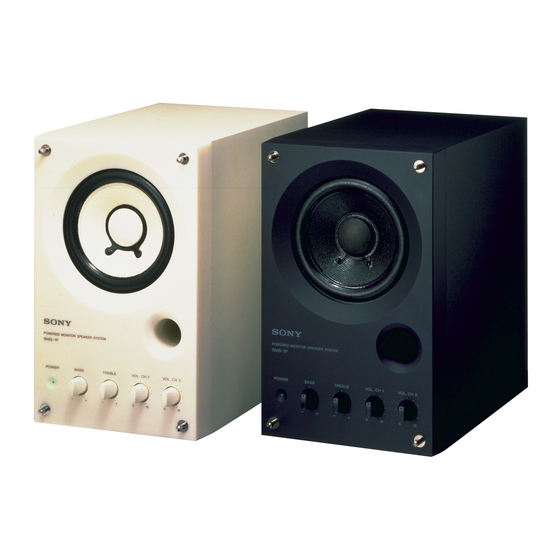
Inhaltszusammenfassung für Sony SMS-1P
- Seite 1 3-810-741-12 (1) SONY Powered Monitor Speaker System Operating Instructions Mode d'emploi Bedienungsanleitung SMS- 1 p Sony Corporation 1996 Printed in Japan...
- Seite 2 Record the serial number in the space provided below. Refer to them whenever you call upon your Sony dealer regarding this To prevent fire or shock prod uct. hazard, do not expose Model No. SMS-IP...
- Seite 3 English If it still persists... Features Check that there is no other source magnetism* near the TV set. Any other source Of magnetism can cause color irregularity due to an • Professional q uality inputs with high handling interaction with the speaker. capacity (Balanced terminal +22 dB, Standard * Examples of sources of magnetism: Rack, and Pin terminals...
- Seite 4 Speaker Connections Placement Placement • The speaker can be p}aced vertically or horizontal • Two of these speakers placed sideway's will fit into an ElA 313 size rack. • When installing the speaker(s) on a stand or rack, use the nuts located in the bottom of the speaker.
-
Seite 5: Précautions D'utilisation
Frangais Si vous observez encore Caractéristiques anomalies... Eloignezlesenceintes du téléviseur. S'il a aucune amélioration... •Entrées de qualité professionnelle tenue de Vérifiez s'il a pasune autresourcede puissance élevée (prise symétrique +22 dB, magnétisme* prés du téléviseur- Toute source de prises standard classiques et miniature +8 dB). magnétisme peat causer des anomalies de •Mélange de deux sources différentes possible. - Seite 6 Position raccordement I'enceinte Position • l.'encemte petit étre installée la verticale ou l'horizontale. Deux enceintes de ce type rentrent dans un rack de dimensions • Lorsque vous installez renceinte (ou deux enceintes) dans un meuble ou un rack, utilise". les ecrou» se trouvant sous l'enceinte.
-
Seite 7: Betrieb
• NachdelnSieden Lautsprecherangeschlossen und an den vorgesehenen Ort gestellt haben, Bei weiterführenden Fragen wenden Sie Sich nehtnen Sie die Schutzabdeckung ab. bitte an den nächsten Sony Handler. Vor Verwendung Lautsprechers Schutzabdeckung abnehmen. • Stellen Sle die l.autstarke nur so hoch ein, daß... -
Seite 8: Beachtung
Anschluß Aufstellung Lautsprechers Aufstellung • Der Lautsprecher kann wahlweise vertikal Oder horizontal aufgestellt "'erden. In ein 3U-FlA-C.estell passen Lautsprecher nebeneinander. • Bei Aufstellung des Lautsprechers auf einem Ständer Oder in einem Gestell befestigen Sie ihn an der Cnterseite Mi-Schrauben (Gewindesteigung mm). - Seite 9 6 CH1 IN Pin plug terminal Pin plug input terminal for channel l. Connect to the output terminal of an audio component (etc.). SONY o (01 1 POWER indicator Lights when the POWER switch is set to the ON position.
- Seite 10 Specifications AUDIO POWER SPECIFICATIONS POWER OUTPUT TOTAL HARMONIC DISTORTION: With 4 ohm load driven, from 40 Hz - 20 kHz; rated 14 watts minimum RMS power. with more than % total harmonic distortion from 250 mw to rated output. Speaker Speaker system Full range bass reflex Speaker unit...
- Seite 11 Rear 3456 1 POWER switch Turns the power to the speakerON / OFF. (Before turning the power ON, be sure the VOL. CH 1 and VOL. CH 2 knobs are set to the "0" position.) 2 AC socket Connect to a wall outlet (120 V in U.S.A or Canada,220-230V in Europe) using the supplied power cord.
- Seite 12 Characteristic data Données caractéristiques Kenndiagramm Output sound pressure, Frequency characteristics / adjustable range of tone controls Niveau de pression sonore, caractéristiques des fréquences/ plage de réglage commandes du timbre Schalldruckpegel und Einfluß der Klangregler auf den Frequenzgang HI MAX FLAT .


