ABB CMS-600 Installationsanleitung
Verfügbare Sprachen
Verfügbare Sprachen
Quicklinks
Circuit Monitoring Systems (CMS)
Installation manual CMS-600 System
1. Scope of delivery
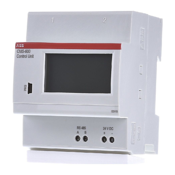
CMS-Bus
interfaces
Touch Display
Connecting terminals
for RS485
Connecting terminals
for 24 V DC
Control Unit CMS-600
2. Mounting the Control Unit
i
• Remove rapid fixation
(RAFIX) before mounting on
SMISSLINE TP
3. Mounting the sensors
1
CMS-1xxPS:
Insert the metal pin of the sensor
into the rear terminal connection
4. Cabling the Control Unit
i
Connecting terminals for
24 V DC and RS485
• max. cable cross-section
2.5 mm
2
• stripping length 13 mm
• current consumption of
Control Unit max. 1.5 A
Current sensors
CMS-1xxPS,
CMS-1xxS8, CMS-1xxDR, CMS-1xxCA,
CMS-2xxS8, CMS-2xxDR, CMS-2xxCA
1a
«click»
DIN-rail mounting
2
«click»
CMS-1xxS8, CMS-2xxS8:
Slip sensor on S800
1
Insert cables into the connecting
terminals
Opening of
sensor to lead
through the
35 x Connector housing
electrical line
LED
Push button
1b
or
«click»
SMISSLINE TP mounting
3
CMS-1xxDR, CMS-2xxDR:
Put cable through opening of
sensor into installation device.
Fix the cable with a cable tie
if needed.
2
Tighten the screws
35 x Connector
Connector set CMS-820
Flat cable
CMS-80x
4
CMS-1xxCA, CMS-2xxCA:
Put cable through opening of
sensor into installation device.
Fix the cable with a cable tie.

Verwandte Anleitungen für ABB CMS-600


Inhaltszusammenfassung für ABB CMS-600
- Seite 3 Stromkreis-Überwachungssystem (CMS) Installationsanleitung CMS-600 System 1. Lieferumfang CMS-Bus- Schnittstellen Durchführung für den Leiter 35 x Steckergehäuse 35 x Steckverbinder Touchdisplay Steckerset CMS-820 Anschlussklemmen für RS485 Drucktaster Anschlussklemmen für 24 V DC Sensoren zur Strommessung Control Unit CMS-600 Flachbandkabel CMS-1xxPS, CMS-1xxS8, CMS-1xxDR, CMS-1xxCA,...
- Seite 4 5. Verkabelung der Sensoren • Steckverbinder dürfen nur einmal verwendet werden • Maximal 32 Sensoren je Control Unit CMS-Bus- Schnittstelle anschliessen • Maximale Länge des Flachbandkabels beach- Flachbandkabel auf CMS-Bus- Platzierung der Steckverbinder Flachbandkabel in Steckergehäuse ten, siehe Bedienungs- einlegen und ganz in Kabelführung Schnittstelle halten mit Stift markieren anleitung CMS-700...