Herunterladen Diese Seite drucken

Werbung

Verfügbare Sprachen

Verfügbare Sprachen

Bedienungsanleitung
DE
Optischer Abstandssensor
UK
Operating instructions
Optical distance sensor
FR
Notice d'utilisation
Détecteur de distance optique
AL010
autosen

Werbung

loading

Inhaltszusammenfassung für autosen AL010

  • Seite 1 Bedienungsanleitung Optischer Abstandssensor Operating instructions Optical distance sensor Notice d‘utilisation Détecteur de distance optique AL010 autosen...
  • Seite 2 Inhalt 1 Vorbemerkung �����������������������������������������������������������������������������������������������������4 1�1 Verwendete Symbole �������������������������������������������������������������������������������������4 1�2 Verwendete Warnhinweise ����������������������������������������������������������������������������4 2 Sicherheitshinweise ���������������������������������������������������������������������������������������������4 3 Bestimmungsgemäße Verwendung ���������������������������������������������������������������������5 3�1 Allgemeine Hinweise �������������������������������������������������������������������������������������5 3�2 Einsatzbereiche ���������������������������������������������������������������������������������������������6 3�3 Einbauhinweise ���������������������������������������������������������������������������������������������6 3�3�1 Vermeidung von Verschmutzung und Umgebungslicht ������������������������6 3�3�2 Vermeidung gegenseitiger Beeinflussung ��������������������������������������������6 3�3�3 Sensorausrichtung zu bewegtem Objekt ����������������������������������������������7 4 Funktionen �����������������������������������������������������������������������������������������������������������7 4�1 Ausgangsfunktion Hysterese �������������������������������������������������������������������������7...
  • Seite 3 10�1 Parametrierung allgemein �������������������������������������������������������������������������17 10�1�1 Einstellung eines Parameterwertes ��������������������������������������������������17 10�1�2 Wechsel von Menü-Ebene 1 zu Menü-Ebene 2 �������������������������������18 10�1�3 Elektronisches Schloss ���������������������������������������������������������������������18 10�2 Parametrierung Grundeinstellungen ����������������������������������������������������������19 10�2�1 Anzeigeeinheit wählen ����������������������������������������������������������������������19 10�2�2 Anzeige einstellen �����������������������������������������������������������������������������19 10�2�3 OUT1 / OUT2 konfigurieren ��������������������������������������������������������������19 10�2�4 Hysteresefunktion �����������������������������������������������������������������������������20 10�2�5 Schaltpunkt für Hysteresefunktion OUT1 / OUT2 einstellen ������������21 10�2�6 Hintergrund-Teach für Hysteresefunktion OUT1 / OUT2 einstellen ��21...
  • Seite 4 1 Vorbemerkung 1.1 Verwendete Symbole ► Handlungsanweisung > Reaktion, Ergebnis […] Bezeichnung von Tasten, Schaltflächen oder Anzeigen → Querverweis Wichtiger Hinweis Fehlfunktionen oder Störungen sind bei Nichtbeachtung möglich� Information Ergänzender Hinweis� 1.2 Verwendete Warnhinweise WARNUNG Warnung vor schweren Personenschäden� Tod oder schwere, irreversible Verletzungen sind möglich� 2 Sicherheitshinweise •...
  • Seite 5 Sichtbares Laserlicht; LASER KLASSE 1� IEC 60825-1 : 2014 entspricht 21 CFR Part 1040 mit Ausnahme der Abweichungen in Übereinstimmung mit der Laser Notice Nr� 50, Juni 2007� Position des Produktlabels Hinweisschild 3 Bestimmungsgemäße Verwendung 3.1 Allgemeine Hinweise Das Gerät wird als optischer Abstandssensor eingesetzt� Das Gerät erfasst kontinuierlich den Abstand zum Objekt und erzeugt Ausgangssignale entsprechend der Parametrierung�...
  • Seite 6 3.2 Einsatzbereiche • Der optische Abstandssensor misst Entfernungen von 2,5��� 150 cm� • Er besitzt eine max� Hintergrundausblendung bis zu 20 m� Der Abstand zwischen Sensor und Hintergrund muss auf max� 20 m begrenzt werden. Ansonsten können Messwerte mehrdeutig sein. → 5.1 3.3 Einbauhinweise 3.3.1 Vermeidung von Verschmutzung und Umgebungslicht Optische Sensoren sind vorzugsweise mit der Frontscheibe nach unten oder...
  • Seite 7 3.3.3 Sensorausrichtung zu bewegtem Objekt Optische Sensoren sind so einzubauen, dass das Objekt seitlich oder von Unten in den Erfassungsbereich des Sensors hineinbewegt wird� Hintergrund: • Beim Einfahren des Objektes von Oben verdeckt das bewegte Objekt zuerst einen Teil der Empfangslinse, ohne dabei vom Sendespot erfasst zu werden� Der Sensor "sieht"...
  • Seite 8 5 Montage 5.1 Montagebedingungen ► Gerät so montieren, dass sich das zu erfassende Objekt im angegebenen Messbereich befindet� Der Eindeutigkeitsbereich des Sensors ist auf 20 m festgelegt� Objekte, die sich außerhalb des Messbereiches befinden, werden bis zur Grenze des Eindeutigkeitsbereiches (20 m) ausgeblendet� Reflektierende Objekte im direkten Strahlengang des Sensors –...
  • Seite 9 6.1 Betrieb mit IO-Link-Master Das Gerät ist kompatibel mit IO-Link Masterportklasse A (Typ A)� Beim Betrieb mit IO-Link Masterportklasse B (Typ B) folgendes beachten: Das Gerät ist standardmäßig nicht kompatibel zur Masterportklasse B (Typ B)� Pin 2 (OU2) wird für herstellerspezifische Funktionen verwendet� Dadurch kann die Hauptversorgungsspannung des Gerätes und die Zusatzspannung (Masterportklasse B an Pin 2) nicht galvanisch getrennt werden�...
  • Seite 10 
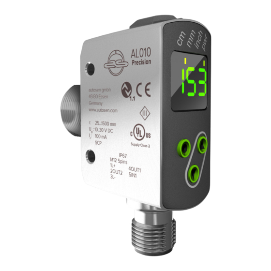
7 Bedien- und Anzeigeelemente 3x LED grün Leuchtende LED = eingestellte Anzeigeeinheit (cm, mm, inch) 1x LED grün Leuchtende LED = Power 1x LED orange Schaltzustand Out 1 1x LED orange Schaltzustand Out 2 Programmiertaste Anwahl der Parameter und Bestätigen der Parameterwerte� [ENTER] Programmiertaste Einstellen der Parameterwerte (kontinuierlich durch Dauerdruck;...
  • Seite 11 Die Grüne Displayfarbe signalisiert, dass sich ein Objekt im überwachten Bereich befindet unabhängig von der Einstellung der Schaltausgänge� Beispiel Abb. 1 (Einstellung Out 1 / Out 2 = hno) Display leuchtet grün, wenn: • Messwert ≤ SP1 • Messwert ≤ SP2 Abb�...
  • Seite 12 8 Menü 8.1 Menü-Struktur für Fensterfunktion 50. 0 55. 0 70. 0 65. 0 40. 0 50. 0 80. 0 85. 0 0. 0 70. 0 0. 0 80. 0 0. 0 0. 0 0. 1 0 40. 0 35. 0 0n 0ff *) Pfeiltaste (hoch oder runter) 3 s gedrückt halten zum Aktivieren�...
  • Seite 13 8.2 Menü-Struktur für Hysteresefunktion 50. 0 60. 0 50. 0 70. 0 80. 0 xno xnc 70. 0 0. 0 0. 0 0. 0 0. 0 ..0. 1 0 0n 0ff *) Pfeiltaste (hoch oder runter) 3 s gedrückt halten zum Aktivieren�...
  • Seite 14 8.3 Menü-Erläuterung Die Werkseinstellungen befinden sich am Ende der Anleitung (→ 15 Werkseinstellung). Konfiguration für Ausgang 1 Es sind 5 Schaltfunktionen einstellbar: [Hno], [Hnc], [Fno], [Fnc] , [OFF] → 10.2.3 OUT1 / OUT2 konfigurieren. Konfiguration für Ausgang 2 Es sind 5 Schaltfunktionen einstellbar: [Hno], [Hnc], [Fno], [Fnc], [OFF] →...
  • Seite 15 Hintergrund-Teach für Hysteresefunktion OUT1 / 2 Grenzwert, bei dem der Ausgang in Hysteresefunktion seinen Schaltzustand ändert (Objekt näher / weiter als eingestellte Entfernung)� [tS1] ist nur aktiv, wenn [OU1] = [Hno] oder [Hnc] [tS2] ist nur aktiv, wenn [OU2] = [Hno] oder [Hnc] (→...
  • Seite 16 9 Betriebsarten 9.1 Run-Modus Der Run-Modus entspricht dem normalen Arbeitsbetrieb� Nach dem Einschalten der Versorgungsspannung befindet sich das Gerät im Run- Modus� Es führt seine Überwachungsfunktion aus und erzeugt Ausgangssignale entsprechend den eingestellten Parametern� Das Display zeigt die aktuelle Entfernung oder die Objektreflektivität an, die gelben LEDs signalisieren den Schaltzustand der Ausgänge�...
  • Seite 17 10 Parametrierung Das Gerät verbleibt während der Parametrierung intern im Arbeitsbetrieb� Es führt seine Überwachungsfunktionen mit den bestehenden Parametern weiter aus, bis die Veränderung abgeschlossen ist� 10.1 Parametrierung allgemein 10.1.1 Einstellung eines Parameterwertes Anzeigeeinheit [Uni] einstellen, bevor die Werte für die Parameter festgelegt werden�...
  • Seite 18 Weitere Parameter einstellen ► In Schritt 1 Parameter wählen und mit Schritt 2 fortfahren� Parametrierung beenden ► 15 s warten oder [Taste hoch] und [Taste runter] drücken� ► ggf� mehrfach wiederholen, um in Menüebene 0 zu gelangen� > Der aktuelle Messwert erscheint� 10.1.2 Wechsel von Menü-Ebene 1 zu Menü-Ebene 2 ►...
  • Seite 19 Entriegeln ► [Taste hoch] + [Taste runter] gedrückt halten, bis [uLo] angezeigt wird� > Das Gerät ist entriegelt� Timeout Wird während des Einstellvorgangs 15 s lang keine Taste gedrückt, geht das Gerät mit unveränderten Werten in den Run-Modus zurück� 10.2 Parametrierung Grundeinstellungen 10.2.1 Anzeigeeinheit wählen [Uni] einstellen, bevor die Werte für die Parameter [SPx], [nPx], [FPx], festgelegt werden�...
  • Seite 20 10.2.4 Hysteresefunktion Die Hysterese hält den Schaltzustand des Ausgangs stabil, wenn der Messwert um den Schaltabstand herum schwankt� Der gewählte Schaltpunkt [SPx] ist dabei der Einschaltpunkt� Der Rückschaltpunkt wird vom Sensor automatisch hinter dem gewählten Schaltpunkt [SPx] eingestellt� Der nominale Abstand zwischen Ein- und Rückschaltpunkt ist die Hysterese, diese kann dem Datenblatt entnommen werden�...
  • Seite 21 Schaltzustand der Ausgänge Ausgangsfunktion Objektabstand (D) Schaltzustand [Hno] D < [SPx] geschlossen D > [SPx] offen [Hnc] D < [SPx] offen D > [SPx] geschlossen 10.2.5 Schaltpunkt für Hysteresefunktion OUT1 / OUT2 einstellen ► In [EF] wechseln� ► Unter [OU1] die Ausgangsfunktion [Hno] oder [Hnc] wählen� ►...
  • Seite 22 Hintergrund sehr hell = Hysterese wird klein gewählt� Der mind� Abstand zwischen Objekt und Hintergrund kann gezielt verkleinert werden, wenn der Hintergrund sehr hell gewählt wird (z�B� weiß)� Ein hellerer Hintergrund ermöglicht die Erkennung kleinerer Objekthöhen� 10.2.8 Fensterfunktion Für jeden der beiden Ausgänge (OUT1 / OUT2) gibt es die Möglichkeit ein Fenster für die Objekterkennung zu definieren�...
  • Seite 23 Schaltzustand der Ausgänge Ausgangsfunktion Objektabstand (D) Schaltzustand D < [nPx] offen [Fno] D > [FPx] [nPx] < D < [FPx] geschlossen D < [nPx] geschlossen [Fnc] D > [FPx] [nPx] < D < [FPx] offen Beide Fenstergrenzen ([nPx] und [FPx]) arbeiten mit einer Schalthysterese →...
  • Seite 24 10.3 Erweiterte Funktionen 10.3.1 Verzögerungszeit für Schaltausgänge einstellen ► In [EF] wechseln� ► Mit [Taste hoch] oder [Taste runter] Parameter wählen: [dSx] = Einschaltverzögerung; [drx] = Ausschaltverzögerung ► Mit [Enter] Parameterwert einstellen: > Eingestellter Parameterwert wird angezeigt� ► [Taste hoch] oder [Taste runter] mind� 3 s lang gedrückt halten� >...
  • Seite 25 Des Weiteren ist die Kommunikation über eine Punkt-zu-Punkt-Verbindung mit einem USB-Adapterkabel möglich� Weitere Informationen zu IO-Link finden Sie unter www�autosen�com� 11.2 Gerätespezifische Informationen Die zur Konfiguration des IO-Link-Gerätes notwendigen IODDs sowie detaillierte Informationen über Sensorwerte, Diagnoseinformationen und Parameter finden Sie in der tabellarischen Übersicht unter www�autosen�com�...
  • Seite 26 Anzeige Mögliche Ursache Schaltausgang [Hno] [Hnc] [Fno] [Fnc] Messobjekt außerhalb des [FAr] Messbereichs >165 cm [OFF] Laser ist ausgeschaltet High [Erp] Plausibilität (z�B� Objekt zu schnell) [SC] Kurzschluss in allen Schaltausgängen Unverändert 13 Wartung, Instandsetzung, Entsorgung Die Instandsetzung defekter Sensoren ist nur durch den Hersteller erlaubt� ►...
  • Seite 27 15 Werkseinstellung Parameter Einstellbereich Werkseinstellung Eigene Einstellung cm, inch Hno, Hnc, Fno, Fnc 3,0���150 3,0���150 3,0���150 Hno, Hnc, Fno, Fnc, OFF 3,0���150 3,0���150 3,0���150 0���0,1���5 0���0,1���5 0���0,1���5 0���0,1���5 0���0,1���5 0,1 s On / OFF...
  • Seite 28 Contents 1 Preliminary note �������������������������������������������������������������������������������������������������30 1�1 Symbols used ����������������������������������������������������������������������������������������������30 1�2 Warnings used ���������������������������������������������������������������������������������������������30 2 Safety instructions ���������������������������������������������������������������������������������������������30 3 Functions and features ��������������������������������������������������������������������������������������31 3�1 General notes ����������������������������������������������������������������������������������������������31 3�2 Application areas �����������������������������������������������������������������������������������������32 3�3 Installation notes ������������������������������������������������������������������������������������������32 3�3�1 Avoidance of soiling and ambient light �����������������������������������������������32 3�3�2 Avoidance of mutual interference �������������������������������������������������������32 3�3�3 Sensor alignment to moving objects ���������������������������������������������������33 4 Functions �����������������������������������������������������������������������������������������������������������33...
  • Seite 29 10 Parameter setting ��������������������������������������������������������������������������������������������43 10�1 General parameter setting �������������������������������������������������������������������������43 10�1�1 Setting a parameter value ����������������������������������������������������������������43 10�1�2 Change from menu level 1 to menu level 2 ��������������������������������������44 10�1�3 Electronic lock ����������������������������������������������������������������������������������44 10�2 Configuration of the basic settings ������������������������������������������������������������45 10�2�1 Selection of the display unit ��������������������������������������������������������������45 10�2�2 Setting the display ����������������������������������������������������������������������������45 10�2�3 Configure OUT1 / OUT2 ������������������������������������������������������������������45 10�2�4 Hysteresis function ���������������������������������������������������������������������������46...
  • Seite 30 1 Preliminary note 1.1 Symbols used ► Instructions > Reaction, result […] Designation of keys, buttons or indications → Cross-reference Important note Non-compliance may result in malfunction� Information Supplementary note� 1.2 Warnings used WARNING Warning of serious personal injury� Death or serious irreversible injuries may result� 2 Safety instructions •...
  • Seite 31 Visible laser light; LASER CLASS 1� IEC 60825-1 : 2014 complies with 21 CFR 1040 except for deviations pursuant to Laser Notice No� 50, dated June 2007� Position of the product label Label 3 Functions and features 3.1 General notes The unit is used as an optical distance sensor�...
  • Seite 32 3.2 Application areas • The optical distance sensor measures distances between 2,5��� 150 cm� • It has a background suppression of up to 20 m� The distance between the sensor and the background must be limited to max. 20 m. Otherwise measured values can be ambiguous. → 5.1 3.3 Installation notes 3.3.1 Avoidance of soiling and ambient light Preferably align photoelectric sensors with the front lens facing downwards or...
  • Seite 33 3.3.3 Sensor alignment to moving objects Photoelectric sensors have to be installed in a way to ensure that the object is moved into the detection range of the sensor from the side or from the bottom� Background: • When the object approaches from the top, it initially covers part of the receiver lens without being detected by the light spot�...
  • Seite 34 5 Installation 5.1 Installation conditions ► Install the unit so that the object to be detected is within the specified measuring range� The unambiguity range of the sensor is fixed to 20 m� Objects outside the measuring range will be suppressed up to the limit of the unambiguity range (20 m)�...
  • Seite 35 6.1 Operation with IO-Link master The unit is compatible with IO-Link master port class A (type A)� For operation with IO-Link master port class B (type B) observe the following: As a standard, the unit is not compatible with master port class B (type B)�...
  • Seite 36 Programming Selection of the parameters and acknowledgement of the button parameter values� [ENTER] Programming Setting of the parameter values (scrolling by holding pressed; button incremental by pressing briefly)� "up" Programming Setting of the parameter values (scrolling by holding pressed; button incremental by pressing briefly)�...
  • Seite 37 Example fig. 1 (setting Out 1 / Out 2 = hno) Display is green if: • measured value ≤ SP1 • measured value ≤ SP2 Fig� 1 1: Display Out1 colour 2: High Out2 3: Low 4: Green 5: Red Example fig.
  • Seite 38 8 Menu 8.1 Menu structure for window function 50. 0 55. 0 70. 0 65. 0 40. 0 50. 0 80. 0 85. 0 0. 0 70. 0 0. 0 80. 0 0. 0 0. 0 0. 1 0 40. 0 35.
  • Seite 39 8.2 Menu structure for hysteresis function 50. 0 60. 0 50. 0 70. 0 80. 0 xno xnc 70. 0 0. 0 0. 0 0. 0 0. 0 ..0. 1 0 0n 0ff *) Keep the arrow key (up or down) pressed for 3 s for activation� Then press the key several times or keep it pressed for fast scrolling�...
  • Seite 40 8.3 Explanation of the menu For the factory settings please refer to the end of these instructions (→ 15 Factory setting)� Configuration for output 1 5 switching functions can be selected: [Hno], [Hnc], [Fno], [Fnc], [OFF] → 10.2.3 Configure OUT1 / OUT2. Configuration for output 2 5 switching functions can be selected: [Hno], [Hnc], [Fno], [Fnc], [OFF] →...
  • Seite 41 Background teach for hysteresis function OUT1 / 2 Limit value at which the output with selected hysteresis function changes its switching state (object nearer/farther than distance set)� [tS1] is only active if [OU1] = [Hno] or [Hnc] [tS2] is only active if [OU2] = [Hno] or [Hnc] →...
  • Seite 42 9 Operating modes 9.1 Run mode The run mode is the normal operating mode� After power on the unit is in the run mode� It carries out its monitoring function and generates output signals according to the set parameters� The display indicates the current distance or the object reflectivity, the yellow LEDs signal the switching state of the outputs�...
  • Seite 43 10 Parameter setting During parameter setting the unit remains internally in the operating mode� It continues its monitoring function with the existing parameters until the change has been completed� 10.1 General parameter setting 10.1.1 Setting a parameter value Set the display unit [Uni] before the values for the parameters are defined� In case of subsequent changes of the display unit rounding errors during internal conversion to other units may falsify the set values.
  • Seite 44 Setting of other parameters ► Select a parameter as described in step 1 and continue with step 2� Finish parameter setting ► Wait for 15 s or press the "up" and "down" button� ► If necessary, repeat several times to access menu level 0� >...
  • Seite 45 Unlocking ► Keep the "up" + "down" button pressed until [uLo] is displayed� > The unit is unlocked� Timeout If no button is pressed for 15 s during the setting procedure, the unit returns to the run mode with unchanged values� 10.2 Configuration of the basic settings 10.2.1 Selection of the display unit Set [Uni] before the values for the parameters [SPx], [nPx], [FPx] are...
  • Seite 46 10.2.4 Hysteresis function The hysteresis keeps the switching state of the output stable if the measured value varies about the sensing range� The selected switch point [SPx] is the set point� The reset point is automatically set above the selected switch point [SPx] by the sensor�...
  • Seite 47 Switching status of the outputs Output function Object distance (D) Switching status [Hno] D < [SPx] Closed D > [SPx] Open [Hnc] D < [SPx] Open D > [SPx] Closed 10.2.5 Setting of the switch point for hysteresis function OUT1 / OUT2 ►...
  • Seite 48 10.2.8 Window function It is possible to define a window for the object recognition for each of the two outputs (OUT1 / OUT2)� Switches when the object is detected [nPx] [FPx] [Fno] [nPx] = switch point "near"; [FPx] = switch point "far"; FE = window If the measured value is between the switch point "near"...
  • Seite 49 Switching status of the outputs Output function Object distance (D) Switching status D < [nPx] Open [Fno] D > [FPx] [nPx] < D < [FPx] Closed D < [nPx] Closed [Fnc] D > [FPx] [nPx] < D < [FPx] Open Both window limit values ([nPx] and [FPx]) work with a switching hysteresis →...
  • Seite 50 The IO-Link interface enables direct access to the sensor values and parameters and provides the possibility to set the parameters of the unit during operation� In addition, communication is possible via a point-to-point connection with a USB adapter cable� You will find more detailed information about IO-Link at www�autosen�com�...
  • Seite 51 You will find the IODDs necessary for the configuration of the IO-Link device and detailed information about sensor values, diagnostic information and parameters in the overview table at www�autosen�com� 11.3 Parameter setting tools You will find all necessary information about the required IO-Link hardware and software at www�autosen�com�...
  • Seite 52 Display Possible cause Switching output [Hno] [Hnc] [Fno] [Fnc] [Erp] Plausibility (e�g� object too fast) [SC] Short circuit in all switching outputs Unchanged 13 Maintenance, repair and disposal Faulty sensors must only be repaired by the manufacturer� ► Keep the front lens of the sensor clean� ►...
  • Seite 53 15 Factory setting Parameter Setting range Factory setting Own setting cm, inch Hno, Hnc, Fno, Fnc 3,0���150 3,0���150 3,0���150 Hno, Hnc, Fno, Fnc, OFF 3,0���150 3,0���150 3,0���150 0���0,1���5 0���0�1���5 0���0�1���5 0���0�1���5 0���0�1���5 0�1 s On / OFF...
  • Seite 54 Contenu 1 Remarque préliminaire ��������������������������������������������������������������������������������������56 1�1 Symboles utilisés �����������������������������������������������������������������������������������������56 1�2 Avertissements utilisés ��������������������������������������������������������������������������������56 2 Consignes de sécurité ���������������������������������������������������������������������������������������56 3 Fonctionnement et caractéristiques �������������������������������������������������������������������57 3�1 Remarques générales ���������������������������������������������������������������������������������57 3�2 Applications �������������������������������������������������������������������������������������������������58 3�3 Remarques sur le montage �������������������������������������������������������������������������58 3�3�1 Conseil / souillure et lumière ambiante �����������������������������������������������58 3�3�2 Eviter une influence mutuelle �������������������������������������������������������������58 3�3�3 Orientation du détecteur vers l‘objet en mouvement ��������������������������59 4 Fonction �������������������������������������������������������������������������������������������������������������59...
  • Seite 55 10 Paramétrage ����������������������������������������������������������������������������������������������������69 10�1 Paramétrage en général ����������������������������������������������������������������������������69 10�1�1 Réglage d‘une valeur de paramètre �������������������������������������������������69 10�1�2 Changement du niveau de menu 1 au niveau de menu 2 ����������������70 10�1�3 Verrou électronique ��������������������������������������������������������������������������70 10�2 Paramétrage des réglages de base ����������������������������������������������������������71 10�2�1 Sélectionner l‘unité d‘affichage ���������������������������������������������������������71 10�2�2 Réglage de l‘affichage ����������������������������������������������������������������������71 10�2�3 Configurer OUT1 OUT2 �������������������������������������������������������������������71 10�2�4 Fonction hystérésis ���������������������������������������������������������������������������72...
  • Seite 56 1 Remarque préliminaire 1.1 Symboles utilisés ► Action à faire > Retour d'information, résultat […] Désignation d'une touche, d'un bouton ou d'un affichage → Référence croisée Remarque importante Le non-respect peut aboutir à des dysfonctionnements ou perturbations� Information Remarque supplémentaire� 1.2 Avertissements utilisés AVERTISSEMENT Avertissement de dommages corporels graves�...
  • Seite 57 Lumière laser visible ; APPAREIL A LASER DE CLASSE 1� CEI 60825-1 : 2014 conforme à 21 CFR Part 1040 à l'exception des déviations suivant Laser Notice No� 50, juin 2007� Position de l'étiquette du produit Panneau indicateur 3 Fonctionnement et caractéristiques 3.1 Remarques générales L'appareil est utilisé...
  • Seite 58 3.2 Applications • Le détecteur de distance optique mesure des distances entre 2,5��� 150 cm� • Il a une suppression de l'arrière-plan jusqu'à 20 m� La distance entre le détecteur et l'arrière-plan doit être limitée à max. 20 m. Sinon, les valeurs mesurées peuvent être ambiguës. → 5.1 3.3 Remarques sur le montage 3.3.1 Conseil / souillure et lumière ambiante De préférence, les détecteurs optoélectroniques doivent être orientés avec leur...
  • Seite 59 3.3.3 Orientation du détecteur vers l'objet en mouvement Les détecteurs optoélectroniques doivent être installés de façon à ce que l'objet soit transporté dans la zone de détection du détecteur latéralement ou depuis le bas� Raison : • Lors de l'approche de l'objet par le haut, l'objet en mouvement couvre d'abord une partie de la lentille réceptrice sans être détecté...
  • Seite 60 5 Montage 5.1 Conditions de montage ► Monter l'appareil de sorte que l'objet à détecter se trouve dans l'étendue de mesure indiquée� La zone d’univocité du détecteur est fixée à 20 m� Des objets en dehors de l'étendue de mesure sont supprimés jusqu'à la limite de la zone sans équivoque (20 m)�...
  • Seite 61 6.1 Fonctionnement avec un maître IO-Link L'appareil est compatible avec le type de port maître IO-Link A (type A)� Observer les remarques suivantes lors d'un fonctionnement avec le type de port maître B (type B) : Normalement, l'appareil n'est pas compatible avec le type de port maître B (type B)�...
  • Seite 62 1x LED orange Etat de commutation Out 2 Bouton de Sélection des paramètres et confirmation des valeurs de programmation paramètres� [ENTER] Bouton de Réglage des valeurs de paramètres (en continu en appuyant programmation sur le bouton-poussoir en permanence ; en pas à pas en "haut"...
  • Seite 63 Exemple fig. 1 (réglage Out 1 / Out 2 = hno) L'afficheur est vert si : • valeur mesurée ≤ SP1 • valeur mesurée ≤ SP2 Fig� 1 1: Couleur de Out1 l'affichage 2: High Out2 3: Low 4: Vert 5: Rouge Exemple fig.
  • Seite 64 8 Menu 8.1 Structure du menu pour la fonction fenêtre 50. 0 55. 0 70. 0 65. 0 40. 0 50. 0 80. 0 85. 0 0. 0 70. 0 0. 0 80. 0 0. 0 0. 0 0. 1 0 40.
  • Seite 65 8.2 Structure du menu pour la fonction hystérésis 50. 0 60. 0 50. 0 70. 0 80. 0 xno xnc 70. 0 0. 0 0. 0 0. 0 0. 0 ..0. 1 0 0n 0ff *) Maintenir appuyée la touche flèche (haut ou bas) pendant 3 s pour l'activer�...
  • Seite 66 8.3 Explication du menu Les réglages usine se trouvent à la fin de cette notice (→ 15 Réglage usine). Configuration pour la sortie 1 5 fonctions de commutation sont réglables : [Hno], [Hnc], [Fno], [Fnc], [OFF] → 10.2.3 Configurer OUT1 OUT2. Configuration pour la sortie 2 5 fonctions de commutation sont réglables : [Hno], [Hnc], [Fno], [Fnc], [OFF] →...
  • Seite 67 Teach-in arrière-plan pour la fonction hystérésis OUT1 / 2 Valeur limite à laquelle la sortie en fonction hystérésis change son état de commutation (objet plus proche / plus éloigné que la distance réglée)� [tS1] est seulement actif si [OU1] = [Hno] ou [Hnc] [tS2] est seulement actif si [OU2] = [Hno] ou [Hnc] (→...
  • Seite 68 9 Modes de fonctionnement 9.1 Mode Run Le mode Run correspond au mode de fonctionnement normal� Après la mise sous tension l'appareil se trouve en mode Run� Il exécute ses fonctions de surveillance et génère les signaux de sortie selon les paramètres réglés�...
  • Seite 69 10 Paramétrage Pendant le paramétrage l'appareil reste en mode de fonctionnement en interne� Il continue à exécuter ses fonctions de surveillance avec les paramètres précédents jusqu'à ce que la modification soit validée� 10.1 Paramétrage en général 10.1.1 Réglage d'une valeur de paramètre Régler l'unité...
  • Seite 70 Réglage d'autres paramètres ► Sélectionner un paramètre comme décrit à l'étape 1 et passer à l'étape 2� Terminer le paramétrage ► Attendre 15 s ou appuyer sur les touches "haut" et "bas"� ► Si nécessaire, répéter plusieurs fois pour accéder au niveau de menu 0� >...
  • Seite 71 Déverrouiller ► Appuyer sur la touche "haut" + "bas" jusqu'à ce que [uLo] soit affiché� > L'appareil est déverrouillé� Timeout Si lors du réglage aucun bouton n'est appuyé pendant 15 s, l'appareil se remet en mode Run sans aucune modification des valeurs� 10.2 Paramétrage des réglages de base 10.2.1 Sélectionner l'unité...
  • Seite 72 10.2.4 Fonction hystérésis L'hystérésis garantit un état de commutation de la sortie stable en cas de fluctuations de la valeur mesurée autour du seuil de commutation� Le seuil de commutation sélectionné [SPx] est le seuil d'enclenchement � Le seuil de déclenchement est automatiquement réglé...
  • Seite 73 Etat de commutation des sorties Fonction de sortie Distance objet (D) Etat de commutation [Hno] D < [SPx] fermé D > [SPx] ouvert [Hnc] D < [SPx] ouvert D > [SPx] fermé 10.2.5 Régler le seuil de commutation pour la fonction hystérésis OUT1 / OUT2 ►...
  • Seite 74 10.2.8 Fonction fenêtre Pour les deux sorties (OUT1 / OUT2), il existe une possibilité de définir une fenêtre pour reconnaître l’objet� Commute si l'objet est détecté [nPx] [FPx] [Fno] [nPx] = seuil de commutation "proche" ; [FPx] = seuil de commutation "éloigné"; FE = fenêtre Si la valeur mesurée est entre le seuil "proche"...
  • Seite 75 Etat de commutation des sorties Fonction de sortie Distance objet (D) Etat de commutation D < [nPx] ouvert [Fno] D > [FPx] [nPx] < D < [FPx] fermé D < [nPx] fermé [Fnc] D > [FPx] [nPx] < D < [FPx] ouvert Les deux limites de la fenêtre ([nPx] et [FPx]) travaillent avec une hystérésis →...
  • Seite 76 10.3 Fonctions étendues 10.3.1 Régler la temporisation pour les sorties de commutation ► Passer à [EF]� ► Sélectionner un paramètre avec la touche "haut" ou "bas" :[dSx] = temporisation à l'enclenchement ; [drx] = temporisation au déclenchement ► En appuyant sur [Enter] régler la valeur du paramètre : >...
  • Seite 77 Vous trouverez plus d'informations sur IO-Link sur www�autosen�com� 11.2 Informations spécifiques à l'appareil Vous trouverez les IODD nécessaires pour la configuration de l'appareil IO-Link ainsi que des informations détaillées concernant les valeurs du détecteur, des informations de diagnostic et les paramètres sous forme de table sur www�autosen�com�...
  • Seite 78 Affichage Cause possible Sortie de commutation [Hno] [Hnc] [Fno] [Fnc] [OFF] Laser est désactivé High [ErP] Plausibilité (par ex� objet trop rapide) [SC] Court-circuit de toutes les sorties de commutation Inchangée 13 Entretien, réparation et élimination Des détecteurs défectueux ne doivent être réparés que par le fabricant� ►...
  • Seite 79 15 Réglage usine Paramètre Plage de réglage Réglage usine Son propre réglage cm, inch Hno, Hnc, Fno, Fnc 3,0���150 3,0���150 3,0���150 Hno, Hnc, Fno, Fnc, OFF 3,0���150 3,0���150 3,0���150 0���0,1���5 0���0,1���5 0���0,1���5 0���0,1���5 0���0,1���5 0,1 s On / OFF...
  • Seite 80 Technische Daten und weitere Informationen unter: Données techniques et informations supplémentaires sur notre site web à: Technical data and further information at: www.autosen.com...