Herunterladen Diese Seite drucken
Baxi LUNA DUO-TEC MP 1.90 Gebrauchsanleitung Für Den Benutzer Und Installateur

Baxi LUNA DUO-TEC MP 1.90 Gebrauchsanleitung Für Den Benutzer Und Installateur

Kondensations-wandgasheizkessel

Werbung

Verfügbare Sprachen

Verfügbare Sprachen

A
it
en
de(AT)
es
MP 1.90 – 1.110
CALDAIA MURALE A GAS A CONDENSAZIONE
Manuale per l'uso destinato all'utente e all'installatore
CONDENSING GAS WALL-HUNG BOILERS
Instructions manual for users and installers
KONDENSATIONS-WANDGASHEIZKESSEL
Gebrauchsanleitung für den Benutzer und Installateur
CALDERA MURAL DE GAS A CONDENSACIÓN
Manual de uso destinado al usuario y al instalador

Werbung

loading

Inhaltszusammenfassung für Baxi LUNA DUO-TEC MP 1.90

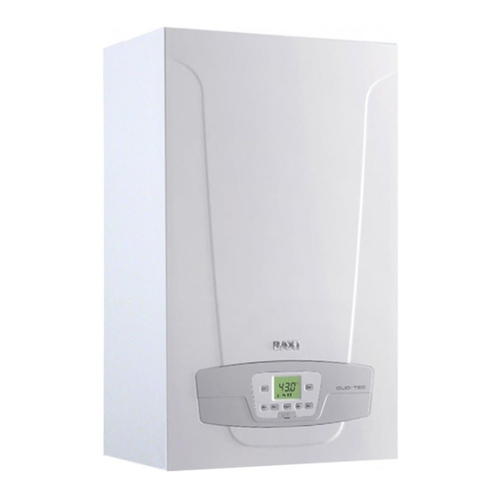
  • Seite 1 MP 1.90 – 1.110 CALDAIA MURALE A GAS A CONDENSAZIONE Manuale per l’uso destinato all’utente e all’installatore CONDENSING GAS WALL-HUNG BOILERS Instructions manual for users and installers de(AT) KONDENSATIONS-WANDGASHEIZKESSEL Gebrauchsanleitung für den Benutzer und Installateur CALDERA MURAL DE GAS A CONDENSACIÓN Manual de uso destinado al usuario y al instalador...
  • Seite 2 Gentile Cliente, la nostra Azienda ritiene che il Suo nuovo prodotto soddisferà tutte le Sue esigenze. L’acquisto di un nostro prodotto garantisce quanto Lei si aspetta: un buon funzionamento ed un uso semplice e razionale. Quello che Le chiediamo è di non mettere da parte queste istruzioni senza averle prima lette: esse contengono informazioni utili La nostra azienda dichiara che questi prodotti sono dotati di marcatura conformemente ai requisiti essenziali delle seguenti Direttive:...
  • Seite 3 Europa nella produzione di caldaie e sistemi per il riscaldamento ad alta (ISO 14001) e per la salute e sicurezza (OHSAS 18001). Questo attesta che BAXI S.p.A. riconosce prodotti, la salute e sicurezza dei propri dipendenti.
  • Seite 4 AVVERTENZE GENERALI Questa caldaia serve a riscaldare l’acqua ad una temperatura inferiore a quella di ebollizione a pressione atmosferica. Essa deve essere allacciata ad un impianto di riscaldamento e ad una rete di distribuzione di acqua calda sanitaria, compatibilmente alle sue 37 del 22.01.08, far effettuare: sull’imballo e dalla targa presente sull’apparecchio.
  • Seite 5 1. MESSA IN FUNZIONE DELLA CALDAIA Procedere come di seguito descritto per le corrette operazioni di accensione: Alimentare elettricamente la caldaia. Selezionare la modalità di riscaldamento desiderata (capitolo 1.2). almeno 2 secondi. Regolazione temperatura acqua sanitaria (tasto + per aumentare la temperatura e tasto – per diminuirla) Regolazione temperatura acqua di riscaldamento (tasto + per aumentare la temperatura e tasto –...
  • Seite 6 2. ARRESTO PROLUNGATO DELL’IMPIANTO. PROTEZIONE ANTIGELO E’ buona norma evitare lo svuotamento dell’intero impianto di riscaldamento poiché ricambi d’acqua possono causare inutili e dannosi depositi di calcare all’interno della caldaia e dei corpi scaldanti. Se durante l’inverno l’impianto termico non dovesse essere utilizzato, nel caso di pericolo di gelo, è...
  • Seite 7 5. MENU INFORMAZIONI DI CALDAIA Agire sul tasto per visualizzare le informazioni riportate nella tabella seguente. Per uscire premere il tasto Descrizione Descrizione Codice interno di anomalia secondario Corrente di ionizzazione Temperatura di mandata riscaldamento Ore di lavoro del bruciatore Temperatura esterna (se la sonda esterna) Temperatura di mandata riscaldamento zona 2 Temperatura acqua bollitore esterno (modelli predisposti)
  • Seite 8 La pompa di caldaia (13 - “SECTION” A) è di tipo modulante e ha lo scopo di far circolare l’acqua tra la caldaia e il separatore “SECTION” E). La circolazione dell’acqua nell’impianto è demandata alle relative pompe (vedere paragrafo 11.2.3). Modello Portata minima (l/h) separatore idraulico BAXI 1.90 2000 4200 1.110...
  • Seite 9 Il camino o canna fumaria utilizzata deve essere idonea all’uso. Per una migliore installazione si consiglia di utilizzare gli accessori forniti dal costruttore. TABELLA 1A In caso d’installazione di condotti di scarico e di aspirazione non forniti da BAXI S.p.A. 1.90 MP 1.110 MP “SECTION”...
  • Seite 10 10.3 CONDOTTI IN CASCATA Questo tipo di condotti permette di evacuare i prodotti della combustione di più caldaie collegate in cascata attraverso un collettore fumi comune. Il collettore deve essere utilizzato solamente per collegare le caldaie alla canna fumaria. I diametri disponibili sono: Ø125 mm - Ø160 mm e Ø200 mm.
  • Seite 11 MORSETTIERA M3 non utilizzato collegamento dispositivi di sicurezza esterni (I.S.P.E.S.L) collegamento pompa bollitore sanitario. collegamento pompa riscaldamento impianto (esterna a valle del separatore idraulico). della caldaia. 11.1 COLLEGAMENTO TERMOSTATO AMBIENTE l’apparecchio non sia alimentato elettricamente. Rispettare la polarità in alimentazione L (LINEA) - N (NEUTRO). Per collegare il Termostato Ambiente alla caldaia, agire come di seguito descritto: Min.
  • Seite 12 Pannello di Controllo Base per Pannello di Controllo a parete Accessorio interfaccia a led Base per Accessorio interfaccia a led Retroilluminazione del display +12V Collegamento di massa Alimentazione/Segnale +12V vedere le informazioni fornite con l’accessorio stesso. IMPOSTAZIONE PARAMETRI MEDIANTE IL CONTROLLO REMOTO SIMBOLOGIA RIFERITA AL CONTROLLO REMOTO Ruotare la manopola B Visualizzazione display...
  • Seite 13 IMPIANTO A ZONE CON INSTALLAZIONE DEL CONTROLLO REMOTO Il collegamento elettrico e le regolazioni necessarie per la gestione di un impianto diviso in zone, in cui è previsto il Controllo istruzioni del Modulo di Espansione fornito come accessorio. REGOLAZIONE TEMPERATURA SU IMPIANTO DI RISCALDAMENTO IN ALTA TEMPERATURA Allo scopo di evitare frequenti accensioni e spegnimenti, si raccomanda di alzare il setpoint minimo di temperatura della caldaia B, il paramentro 740 REGOLAZIONE TEMPERATURA SU IMPIANTO DI RISCALDAMENTO A BASSA TEMPERATURA...
  • Seite 14 11.2.7 IMPIANTO SOLARE (“SECTION” F) Tramite l’utilizzo del modulo esterno AGU 2.550, fornito come accessorio, è possibile gestire un impianto solare. Per il collegamento dell’impianto vedere le istruzioni fornite con l’accessorio stesso. 11.3 COLLEGAMENTO SICUREZZE I.S.P.E.S.L. I dispositivi di sicurezza previsti dalla Raccolta R (termostato e pressostato di sicurezza circuito di riscaldamento), devono essere collegati elettricamente (in serie) ai morsetti 2-3 della morsettiera M3.
  • Seite 15 14. IMPOSTAZIONE PARAMETRI Per programmare i parametri della scheda elettronica della caldaia, agire nel modo seguente: Premere contemporaneamente i tasti programma “P02 Premere il tasto On”, rilasciare il tasto e sul display appare “P01 Agire sui tasti Premere il tasto , il valore del parametro selezionato inizia a lampeggiare, agire sui tasti Premere il tasto per confermare il valore oppure premere il tasto...
  • Seite 16 5715 5730 5890 5931 * Ingresso sonda BX2 5932 * Ingresso sonda BX3 5977 * Ingresso H5 ( Ingresso H2 modulo 1 (Ingresso multifunzione) Versione Software Indirizzo dispositivo LPB (collegamento via BUS) Indirizzo segmento LPB (collegamento via BUS) Sorgente orologio Tempo trascorso dopo la manutenzione mesi 9512...
  • Seite 17 TABELLA 2 VENTURI UGELLI GAS CO Max P60** P30 – P61 ** P59** Ø (mm) Ø (mm) (ppm) Potenza min Potenza max Potenza accensione Modello caldaia G20-G31 G20 G31 G20 G31 G20/G31 1.90 1250 1500 6500 6200 2400 2400 *8,5 *9,9 *9,0 *10 <...
  • Seite 18 In caso di mancanza di richiesta di calore, in riscaldamento e/o in sanitario, per un tempo di 24 ore consecutive le pompe si mettono in funzione automaticamente per 10 secondi. Questo dispositivo, tarato a 4 bar, è a servizio del circuito di riscaldamento. Si consiglia di raccordare la valvola di sicurezza ad uno scarico sifonato.
  • Seite 19 18.2 PULIZIA DELLO SCAMBIATORE LATO FUMI Per pulire lo scambiatore di calore, procedere come di seguito descritto: Togliere l’alimentazione elettrica alla caldaia. Chiudere il rubinetto di ingresso gas. Rimuovere il coperchio frontale dalla caldaia. Abbassare la scatola elettrica, assicurandosi di proteggerla dal contatto con l’acqua.
  • Seite 20 18.4 PARAMETRI DI COMBUSTIONE Per la misura in opera del rendimento di combustione e dell’igienicità dei prodotti di collegata al circuito scarico dei fumi (A) mediante la quale è possibile rilevare l’igienicità dei prodotti della combustione ed il rendimento di combustione. L’altra è collegata al circuito di aspirazione dell’aria comburente (B dei prodotti della combustione nel caso di condotti coassiali.
  • Seite 21 20. CARATTERISTICHE TECNICHE 1.90 1.110 Categoria 2H3P Tipo di gas G20 - G31 Portata termica nominale 87,4 104,9 Portata termica ridotta (G20) 11,7 Portata termica ridotta (G31) 12,5 11,7 85,0 102,0 92,3 110,3 11,4 12,2 11,4 10,2 12,3 13,1 12,3 97,3 97,2 105,5...
  • Seite 22 Dear Customer, expectations: good performance combined with simple and rational use. product. Our company declares that these products are marked in compliance with the essential requirements of the following Directives: - Gas Directive 2009/142/EC 92/42/EEC - Electromagnetic Compatibility Directive 2004/108/EC - Low Voltage Directive 2006/95/EC Our company, constantly striving to improve the products, reserves the right to modify the details given in this documentation at any time and without notice.
  • Seite 23 European manufacturer of hi-tech boilers and heating systems, has developed safety (OHSAS 18001) systems. This means that BAXI S.p.A. includes among its objectives the safeguarding of the environment, the reliability and quality of its products, and the health and safety of its employees.
  • Seite 24 GENERAL PRECAUTIONS This boiler has been designed to heat water to a temperature lower than boiling point at atmospheric pressure. It must be connected to a central heating system and to a domestic hot water supply system according to its performance and power output. Make sure that the boiler is adjusted to use the type of gas delivered by the gas supply.
  • Seite 25 1. COMMISSIONING THE BOILER To light the boiler correctly, proceed as follows: Select the required heating mode (section 1.2). for at least 2 seconds. DHW temperature adjustment (+ to increase the temperature and – to decrease it) Heating water temperature adjustment (+ to increase the temperature and –...
  • Seite 26 2. PROLONGED SHUTDOWN. ANTI-FREEZE PROTECTION boiler and the heating elements. If the boiler is not used during winter and is therefore exposed to the danger of frost, add some boiler management system includes a “frost protection” function for the heating system which, when delivery temperature falls blocked.
  • Seite 27 5. BOILER INFORMATION MENU Press to display the information indicated in the following table. Press to exit. Description Description SW Diagnostic Code Ion current Burner working hours Zone 1 heating mode Zone 2 heating mode Water pressure in heating system DHW circuit operating mode Heating return temperature Boiler operating mode...
  • Seite 28 INSTRUCTIONS PRIOR TO INSTALLATION The following notes and instructions are addressed to installers to allow them to carry out trouble-free installation. Instructions for igniting and using the boiler are contained in the ‘Instructions for Users’ section. The installation must satisfy the requirements of standards and local by-laws and technical regulations.
  • Seite 29 10. INSTALLING THE DUCTS accessories, as described below. The boiler has been designed for connection to a vertical the accessory splitting kit. WARNINGS instructions are provided with the individual accessories. used. TABLE 1A 1.90 MP the table to the side. 1.110 MP “SECTION”...
  • Seite 30 10.3 CASCADE FLUES This type of duct evacuates the products of combustion of more than one boiler in a cascade connection through a shared fumes and Ø200 mm. A range of accessories is available on request. TABLE 1B PARAMETER P60 MAXIMUM NUMBER OF BOILERS Revs/min (rpm) at minimum IN CASCADE CONNECTION...
  • Seite 31 TERMINAL BLOCK M3 not used. storage boiler pump connection. system heating pump connection (external downline from hydraulic separator). Use the relative cable grommets at the bottom of the boiler to thread the cables through to the terminal blocks. 11.1 CONNECTING THE ROOM THERMOSTAT To connect the Room Thermostat to the boiler, proceed as described below: Min.
  • Seite 32 Control Panel Base for wall-mounted Control Panel Led interface accessory Base for Led interface accessory Display backlighting +12V Earth connection Power input/Signal +12V SETTING PARAMETERS USING THE REMOTE CONTROL SYMBOLS FOR REMOTE CONTROL Turn knob B Display shows Press knob B Press button A and knob B together Press button A or C Press buttons A and C together...
  • Seite 33 ZONE SYSTEM WITH INSTALLATION OF THE REMOTE CONTROL The electrical connection and the adjustments required to manage a system divided into zones with use of the Remote Control Expansion Module supplied as an accessory. ADJUSTING THE TEMPERATURE OF THE HIGH TEMPERATURE HEATING SYSTEM To avoid frequent starting and stopping, raise the minimum temperature setpoint of the boiler in the heating mode by setting parameters 740 TEMPERATURE ADJUSTMENT ON LOW TEMPERATURE HEATING SYSTEM...
  • Seite 34 11.2.7 SOLAR PLANT (“SECTION” F) Use the AGU 2.550 external unit, supplied as an accessory, to manage a solar plant. To connect the plant, see the instructions supplied with the accessory. 12. SPECIAL FUNCTIONS 12.1 SYSTEM GAS EXTRACTION FUNCTION maintenance when the water is drained from the primary circuit. To enable the system gas extraction function press buttons together for 6 seconds.
  • Seite 35 14. PARAMETERS SETTING To programme the parameters of the boiler electronic board, proceed as follows: Press together and hold them down for 6 seconds until programme row “P02” appears on the display alternated with Press and hold down for 6 seconds until “On” appears on the display. Release the button and “P01 Press Press Press...
  • Seite 36 5715 5730 5890 Not used (Do NOT change this parameter) 5931 *BX2 sensor input 5932 *BX3 sensor input 5977 *Input H5 Input H2 module 1 (multifunction input) Building time constant (depending on the insulations of the building) Software version LPB device address (BUS connection) LPB segment address (BUS connection) Clock time source Time after maintenance...
  • Seite 37 TABLE 2 PARAMETERS - rpm P60** P30 – P61** P59** VENTURI GAS NOZZLES Max. CO Ø (mm) Ø (mm) (ppm) Min. power Max. power Ignition power Boiler model G20-G31 G20 G31 G20 G31 G20/G31 1.90 1250 1500 6500 6200 2400 2400 *8,5 *9,9 *9,0 *10 <...
  • Seite 38 Pump anti-block function If no heat demand is received in the heating and/or DHW modes for 24 consecutive hours, the pumps will automatically start and operate for 10 seconds. This device is set to 4 bar and is used for the heating circuit. Connect the safety valve to a drain trap. Do not use it to drain the heating circuit.
  • Seite 39 18.2 CLEANING THE HEAT EXCHANGER FUMES SIDE Proceed as follows to clean the heat exchanger: Disconnect the boiler from the mains power supply. Close the gas inlet valve. Remove the front cover from the boiler. Lower the electrical box, ensuring it is protected against contact with water.
  • Seite 40 18.4 COMBUSTION PARAMETERS discharge circuit (A), and allows monitoring of the quality of the combustion products and allowing checking of any recycling of the combustion products in case of coaxial pipelines. oxygen O or carbon dioxide CO concentration carbon monoxide CO concentration. The temperature of the comburent air must be measured on the test point located on the air B) by inserting the measurement sensor by about 9 cm (C).
  • Seite 41 20. TECHNICAL SPECIFICATIONS 1.90 1.110 Cat. 2H3P Gas used G20 - G31 Rated heat input 87,4 104,9 Reduced heat input (G20) 11,7 Reduced heat input (G31) 12,5 11,7 85,0 102,0 91,8 110,2 11,4 12,2 11,4 10,2 12,3 13,1 12,3 97,3 97,2 105,5 105,1...
  • Seite 42 Sehr geehrter Kunde! Unser Unternehmen ist überzeugt, dass Ihr neues Produkt voll und ganz Ihren Anforderungen entsprechen wird. Der Kauf eines unserer Produkte ist Garantie für einen einwandfreien Betrieb und eine einfache und rationelle Verwendung. Bitte legen Sie diese Anleitungen nicht beiseite, ohne sie vorher gelesen zu haben: Sie enthalten nützliche Informationen für den Unser Unternehmen erklärt, dass diese Produkte eine Kennzeichnung besitzen und den grundlegenden Anforderungen der folgenden Richtlinien entsprechen:...
  • Seite 43 Merkmalen. Die betriebsinternen Systeme von Baxi sind nach CSQ nach ISO 14001 und das Gesundheits- und Sicherheitssystem nach OHSAS 18001. Dies bezeugt, dass die Unternehmensphilosophie von BAXI S.p.A. auf den Schutz der Umwelt, auf die Verlässlichkeit und Qualität der eigenen Produkte, sowie auf die Gesundheit und Sicherheit der eigenen Mitarbeiter ausgerichtet ist.
  • Seite 44 ALLGEMEINE HINWEISE Der Heizkessel heizt das Wasser auf eine Temperatur unterhalb des Siedepunktes bei Luftdruck auf. Er muss an eine Heizungsanlage und an ein Warmwasserverteilernetz angeschlossen werden, die seinen Eigenschaften und seiner Leistung angeschlossen wird, muss: überprüft werden, ob der Heizkessel für den Betrieb mit der zur Verfügung stehenden Gasart vorgesehen ist. Die entsprechenden kontrolliert werden, ob der Kamin über einen angemessenen Zug verfügt, keine Drosselstellen aufweist und an denselben Rauchfang keine anderen Geräte angeschlossen sind, wenn dieser nicht ausdrücklich gemäß...
  • Seite 45 1. INBETRIEBNAHME DES HEIZKESSELS Für ein korrektes Einschalten des Heizkessels ist wie folgt vorzugehen: Kontrollieren, ob der Anlagendruck den vorgeschriebenen Werten entspricht (Kapitel 6). Den Heizkessel an das Stromnetz anschließen. Den Gashahn öffnen (gelb, normalerweise unter dem Heizkessel angebracht). Den gewünschten Heizmodus einstellen (Kapitel 1.2). bis das Gas den Brenner erreicht.
  • Seite 46 2. LÄNGERER STILLSTAND DER ANLAGE. FROSTSCHUTZ Ein Entleeren der gesamten Heizanlage sollte nach Möglichkeit vermieden werden, weil ein Wasserwechsel zu unnötigen und schädlichen Kalkablagerungen im Inneren des Heizkessels und der Heizvorrichtungen führen kann. Falls die Heizanlage im Winter nicht verwendet wird und Frostgefahr besteht, wird empfohlen, dem Wasser in der Anlage geeignete Frostschutzmittel beizugeben (z.B.
  • Seite 47 5. INFO-MENÜ HEIZKESSEL Die Taste betätigen, um die in der folgenden Tabelle enthaltenenen Informationen anzuzeigen. Das Menü durch Druck auf die Taste verlassen. Interner Fehlercode Sekundärkreis Ionisierungsstrom Vorlauftemperatur Heizung Arbeitsstunden Brenner Außentemperatur (wenn Außentemperaturfühler vorhanden) Vorlauftemperatur Heizung Zone 2 Wassertemperatur externer Warmwasserspeicher Betriebsart Heizung Zone 1 (vorgesehene Modelle) Wassertemperatur externer Warmwasserspeicher...
  • Seite 48 HINWEISE VOR DER INSTALLATION Die nachfolgenden Hinweise und technischen Anleitungen sind für die Installateure bestimmt, um den Heizkessel einwandfrei zu Teil. Die Installation muss den Bestimmungen sowie den Gesetzen und vor Ort gültigen Richtlinien entsprechen. Installation, Einstellung und erste Inbetriebnahme dürfen nur von einem zugelassenen Fachmann durchgeführt werden. Die Vorschriften der Gasversorgungsunternehmen sowie die Vorschriften der örtlichen Bauordnung sind einzuhalten.
  • Seite 49 Der verwendete Schornstein oder Rauchabzug muss für den vorgesehenen Zweck geeignet sein. TABELLE 1A Bei der Installation von Ablass- und Ansaugleitungen, die nicht von BAXI S.p.A. geliefert werden, müssen diese für die Art der Verwendung zugelassen sein. Ihr max. 1.90 MP Strömungsverlust muss den Werten der seitlich dargestellten Tabelle entsprechen.
  • Seite 50 10.3 KASKADE-LEITUNGEN Durch diese Leitungen werden die Verbrennungsprodukte mehrerer, in Kaskade verbundener Heizkessel durch einen gemeinsame Abgas-Sammelleitung abgeführt. Die Sammelleitung darf nur für den Anschluss der Heizkessel an den Schornstein verwendet werden. Es sind folgende Durchmesser vorhanden: Ø125 mm, Ø160 mm und Ø200 mm. Auf Wunsch ist eine Auswahl von Zubehörteilen erhältlich.
  • Seite 51 KLEMMENLEISTE M3 nicht verwendet. Pumpenanschluss Warmwasserspeicher. Pumpenanschluss Heizanlage (extern nach der hydraulischen Weiche). einsetzen. 11.1 ANSCHLUSS RAUMTHERMOSTAT Für den Anschluss des Raumthermostats an den Heizkessel, wie folgt vorgehen: Min. 200 mm Vor jeglichem Eingriff die Stromversorgung zum Heizkessel abtrennen. Auf die Klemmleiste M1 zugreifen. Die Brücke der Kontaktenden 1-2 entfernen und die Kabel des Raumthermostats anschließen.
  • Seite 52 Schalttafel Basis für die wandseitig zu montierende Schalttafel Zubehör Led-Schnittstelle Basis für Zubehör Led-Schnittstelle Display-Beleuchtung +12V Erdungsanschluss Speisung/Signal +12V PARAMETEREINGABE MIT DER FERNBEDIENUNG SYMBOLE DER FERNBEDIENUNG Den Drehknopf B drehen Display-Anzeige Den Drehknopf B drücken Die Taste A und den Drehknopf B gleichzeitig drücken Die Taste A oder C drücken Die Taste A und C gleichzeitig drücken ZEICHENERKLÄRUNG DES MENÜS...
  • Seite 53 ZONENANLAGE MIT INSTALLATION DER FERNBEDIENUNG Der elektrische Anschluss und die erforderlichen Einstellungen für die Steuerung einer nach Zonen getrennten Anlage, für die Fernbedienung vorgesehen ist, unterscheiden sich je nach den mit dem Heizkessel verbundenen zusätzlichen Einrichtungen. Für verwiesen. TEMPERATURREGELUNG BEI HEIZANLAGEN MIT HOHER TEMPERATUR Heizmodus erhöht werden, und zwar nach dem unter Punkt B 740 auf einem Wert TEMPERATURREGELUNG BEI HEIZANLAGEN MIT NIEDRIGER TEMPERATUR...
  • Seite 54 11.2.7 SOLARANLAGE („SECTION“ F) Mit dem als Zubehör gelieferten externen Modul AGU 2.550 kann eine Solaranlage gesteuert werden. Für den Anschluss der Anage wird auf die mit dem Zubehör gelieferten Anleitungen verwiesen. 12. SPEZIALFUNKTIONEN 12.1 ENTLÜFTUNGSFUNKTION Mit dieser Funktion kann bei der Installation des Heizkessels oder nach Instandhaltungsarbeiten, die das Ablassen des Wassers aus dem Primärkreislauf erforderten, der Heizkreislauf leichter entlüftet werden.
  • Seite 55 14. PARAMETEREINSTELLUNG Zum Programmieren der Parameter der elektronischen Kartenbaugruppe des Heizkessels ist folgendermaßen vorzugehen: Die Tasten gleichzeitig drücken und 6 Sekunden lang gedrückt halten, bis auf dem Display die Programmzeile “P02” Die Taste drücken und 6 Sekunden lang gedrückt halten, bis auf dem Display die Meldung “On” erscheint. Danach die Taste loslassen.
  • Seite 56 5710 5715 5730 ohne Trinkwasserspeicher) 5890 Nicht verwendet (diesen Parameter NICHT ändern) 5931 * Eingang Fühler BX2 5932 * Eingang Fühler BX3 5977 * Eingang H5 ( Eingang H2 Modul 1 (Multifunktionseingang) Zeitkonstante im Gebäude (hängt von der Gebäudeisolierung ab) Std.
  • Seite 57 TABELLE 2 PARAMETER - Umdrehungen/min. (rpm) VENTURI GASDÜSEN CO max P60** P30 – P61** P59** Ø (mm) Ø (mm) (ppm) Mindestleistung Höchstleistung Zündungsleistung Heizkesselmodell G20-G31 G20 G31 G20 G31 G20/G31 5,6(2 4,5(2 1.90 1250 1500 6500 6200 2400 2400 *8,5 *9,9 *9,0 *10 Stk.) Stk.) <...
  • Seite 58 Frostschutz Die elektronische Steuerung des Heizkessels ist mit einer “Frostschutz”-Funktion im Heiz- und Warmwassermodus ausgestattet, dem vorgegebenen Wert entspricht. Anti-Blockier-Sicherheit der Pumpe Liegt 24 Stunden lang keine Wärmeanforderung vor (Heiz- bzw. Warmwassermodus), setzt sich die Pumpe automatisch 10 Sekunden lang in Betrieb. Dieses auf 4 bar geregelte Gerät dient für den Heizkreislauf.
  • Seite 59 18.2 REINIGUNG DES AUSTAUSCHERS AUF DER ABGASSEITE Zum Reinigung des Wärmetauschers ist wie folgt vorzugehen: Die Stromversorgung des Heizkessels abschalten. Den stirnseitigen Deckel des Kessels entfernen. Den Schaltschrank absenken und sicherstellen, dass dieser vor Wasser geschützt ist. Die Kabel der Zündelektrode, der Flammenermittlungsvorrichtung und des Flansch-Thermostats des Wärmeaustauscher abhängen.
  • Seite 60 18.4 VERBRENNUNGSPARAMETER Um die Verbrennungsleistung und die Umweltverträglichkeit der Verbrennungsprodukte Entnahmepunkten ausgestattet. Ein Entnahmepunkt ist an den Abgaskreis (A) angeschlossen und dient zur Messung der Umweltverträglichkeit der Verbrennungsprodukte und des feuerungstechnischen Wirkungsgrads. Der andere Entnahmepunkt ist an den Saugkreis der Verbrennungsluft (B) angeschlossen und dient zur Ermittlung einer eventuellen Rückströmung der Verbrennungsprodukte bei koaxialen Leitungen.
  • Seite 61 20. TECHNISCHE DATEN 1.90 1.110 Kategorie 2H3P Gasart G20 - G31 Nennwärmebelastung Heizung 87,4 104,9 Reduzierte Wärmebelastung (G20) 11,7 Reduzierte Wärmebelastung (G31) 12,5 11,7 85,0 102,0 91,8 110,2 11,4 12,2 11,4 10,2 12,3 13,1 12,3 97,3 97,2 105,5 105,1 107,5 107,4 Max.
  • Seite 62 Estimado Cliente, nuestra Empresa opina que su nuevo producto satisfará todas sus exigencias. La compra de un nuestro producto garantiza lo que Ud. se espera: un buen funcionamiento y un uso simple y racional. de su producto. Nuestra empresa declara que estos productos llevan el marcado con arreglo a los requisitos esenciales de las siguientes Directivas: - Directiva de Gas 2009/142/CE...
  • Seite 63 BAXI , una de las empresas líderes en Europa en la producción de calderas y sistemas para la (OHSAS 18001). Esto atestigua que BAXI S.p.A. reconoce como sus propios objetivos estratégicos la seguridad de sus empleados. La empresa, a través de su organización, está constantemente comprometida en implementar y mejorar estos aspectos para conseguir la satisfacción de sus clientes.
  • Seite 64 ADVERTENCIAS GENERALES Esta caldera sirve para calentar agua a una temperatura inferior a la de ebullición, a presión atmosférica. Debe conectarse a una instalación de calefacción y a una red de distribución de agua caliente sanitaria dentro de los límites de sus prestaciones y de su Controlar que la caldera esté...
  • Seite 65 1. PUESTA EN MARCHA DE LA CALDERA Para encender la caldera correctamente, actuar del siguiente modo: Seleccionar la modalidad de calefacción deseada (capítulo 1.2). Regulación de la temperatura del agua sanitaria (tecla + – para reducirla) Regulación de la temperatura del agua de calefacción (tecla + –...
  • Seite 66 2. PARADA PROLONGADA DE LA INSTALACIÓN. PROTECCIÓN ANTIHELADAS Es buena costumbre evitar el vaciado de toda la instalación de calefacción porque los cambios de agua producen también inútiles y dañinos depósitos calcáreos dentro de la caldera y de los cuerpos calentadores. Si en invierno la instalación no se propilenglicol mezclado con inhibidores de incrustaciones y corrosión.
  • Seite 67 5. MENÚ INFORMACIÓN DE CALDERA Actuar sobre la tecla para visualizar la información contenida en la siguiente tabla. Para salir, pulsar la tecla Código interior de anomalía secundario Corriente de ionización Temperatura de impulsión calefacción Horas de trabajo del quemador Temperatura exterior (si está...
  • Seite 68 (véase el apartado 11.2.3). Controlar que el caudal del agua de circulación en la caldera no sea inferior al valor que se indica en la siguiente tabla: Caudal de trabajo (l/h) con Modelo Caudal mínimo (l/h) separador hidráulico BAXI 1.90 2000 4200 1.110...
  • Seite 69 10. INSTALACIÓN DE LOS CONDUCTOS accesorios suministrados y descritos a continuación. Originalmente, la caldera está preparada para la conexión a un conducto de evacuación - aspiración de tipo coaxial, vertical u horizontal. La caldera también se puede utilizar con conductos separados, utilizando el accesorio desdoblador.
  • Seite 70 10.3 CONDUCTOS EN CASCADA Este tipo de conductos permite evacuar los productos de la combustión de diferentes calderas conectadas en cascada a través de un colector de humos común. El colector se debe utilizar solamente para conectar las calderas al conducto de humo. Los diámetros disponibles son: Ø125 mm - Ø160 mm y Ø200 mm.
  • Seite 71 BORNERA M3 no utilizados. conexión bomba calentador ACS. conexión bomba de calefacción instalación (exterior después del separador hidráulico). de la caldera. 11.1 CONEXIÓN DEL TERMOSTATO AMBIENTE Para conectar el Termostato Ambiente a la caldera, actuar como se describe a continuación: Min.
  • Seite 72 Panel de Control Base para Panel de Control en la pared Accesorio interfaz de leds Base para Accesorio interfaz de leds Retroiluminación de la pantalla +12V Conexión de masa Alimentación/Señal +12V CONFIGURACIÓN DE LOS PARÁMETROS MEDIANTE EL REGULADOR CLIMÁTICO SIMBOLOGÍA REFERIDA AL REGULADOR CLIMÁTICO Girar el mando B Visualización pantalla Pulsar el mando B...
  • Seite 73 INSTALACIÓN DE ZONAS CON INSTALACIÓN DEL REGULADOR CLIMÁTICO La conexión eléctrica y las regulaciones necesarias para la gestión de una instalación dividida en zonas, que requiere del instrucciones del suministrado como accesorio. REGULACIÓN DE LA TEMPERATURA EN UNA INSTALACIÓN DE CALEFACCIÓN A ALTA TEMPERATURA Para evitar encendidos y apagados frecuentes, se recomienda aumentar el ajuste mínimo de temperatura de la caldera en Calefacción B, el parámetro 740 REGULACIÓN DE LA TEMPERATURA EN UNA INSTALACIÓN DE CALEFACCIÓN A BAJA TEMPERATURA...
  • Seite 74 11.2.7 INSTALACIÓN SOLAR (ANEXO - “SECTION” F) Utilizando el módulo interior AGU 2.550, suministrado como accesorio, es posible gestionar una instalación solar (véase la SECCIÓN G). Para la conexión de la instalación véanse las instrucciones facilitadas con el accesorio. 12. FUNCIONES ESPECIALES 12.1 FUNCIÓN PURGADO DE LA INSTALACIÓN Esta función permite facilitar la eliminación del aire en el interior del circuito de Calefacción cuando se instala la caldera en el lugar correspondiente o después de operaciones de mantenimiento que requieren el vaciado del agua del circuito primario.
  • Seite 75 14. CONFIGURACIÓN DEL LOS PARÁMETROS Pulsar a la vez las teclas y mantenerlas pulsadas durante 6 segundos hasta que en la pantalla aparezca la línea de programa “P02 Pulsar la tecla y mantenerla pulsada durante 6 segundos hasta que en la pantalla aparezca la indicación “On”, luego soltar Actuar sobre las teclas Pulsar la tecla : el valor del parámetro seleccionado inicia un parpadeo.
  • Seite 76 5710 5715 5730 5890 5931 * Entrada sonda BX2 5932 * Entrada sonda BX3 5977 * Entrada H5 ( Entrada H2 módulo 1 (Entrada multifunción) horas Versión Software Dirección dispositivo LPB (conexión por BUS) Dirección segmento LPB (conexión por BUS) Fuente reloj Tiempo transcurrido después del mantenimiento meses...
  • Seite 77 TABLA 2 INYECTORES DE VENTURI mín. máx. CO máx. P60** P30 – P61** P59** Ø (mm) (ppm) Ø (mm) Potencia Potencia Potencia encendido Modelo de mín. máx. caldera G20-G31 G20 G31 G20 G31 G20/G31 1.90 1250 1500 6500 6200 2400 2400 *8,5 *9,9 *9,0 *10 <...
  • Seite 78 La gestión electrónica de la caldera está provista de una función “antihielo” en calefacción y ACS que, con temperatura de operativa si la caldera está alimentada eléctricamente, si hay gas y si la presión de la instalación es la establecida. En caso de falta de demanda de calor, en calefacción y/o ACS, por un periodo de 24 horas consecutivas, las bombas se ponen en funcionamiento automáticamente por 10 segundos.
  • Seite 79 18.2 LIMPIEZA DEL INTERCAMBIADOR LADO HUMOS Para limpiar el intercambiador de calor, actuar según se describe a continuación: Cortar la alimentación eléctrica de la caldera. Cerrar el grifo de entrada gas. Quitar la tapa frontal de la caldera. Bajar la caja eléctrica, asegurándose de protegerla contra el con- tacto con el agua.
  • Seite 80 18.4 PARÁMETROS DE COMBUSTIÓN Para la medición en obra del rendimiento de la combustión y de la higienicidad de los productos de la combustión, la caldera está provista de dos tomas destinadas a este uso A) y permite medir la higienicidad de los productos de la combustión y el rendimiento de la combustión. La otra está...
  • Seite 81 20. CARACTERÍSTICAS TÉCNICAS 1.90 1.110 Cat. 2H3P Tipo de gas G20 - G31 Capacidad térmica nominal 87,4 104,9 Capacidad térmica reducida (G20) 11,7 Potencia térmica nominal (G31) 12,5 11,7 85,0 102,0 91,8 110,2 11,4 12,2 11,4 10,2 12,3 13,1 12,3 97,3 97,2 105,5...
  • Seite 82 7115213.01 (4-10/14)
  • Seite 83 Ventilatore Collettore miscela aria-gas Air/gas blend manifold Scambiatore primario Primary exchanger Raccordo scarico fumi coassiale Sonda fumi Flue sensor Valvola di sfogo aria automatica Automatic air vent Elettrodo di accensione Ignition electrode Sonda NTC riscaldamento (mandata e ritorno) Termostato di sicurezza (sovratemperature) Flame detection electrode Accenditore Spark generator...
  • Seite 84 7115213.01 (4-10/14)
  • Seite 85 7115213.01 (4-10/14)
  • Seite 86 7115213.01 (4-10/14)
  • Seite 87 7115213.01 (4-10/14)
  • Seite 88 7115213.01 (4-10/14)
  • Seite 89 7115213.01 (4-10/14)
  • Seite 90 MP 90 MP 110 Q (l/h) Q (l/h) QAC34 7115213.01 (4-10/14)
  • Seite 91 AGU 2.550 CR_0349 AVS 75 CR_0349 7115213.01 (4-10/14)
  • Seite 92 Tmax = 50 °C CG_2482 7115213.01 (4-10/14)
  • Seite 93 7115213.01 (4-10/14)
  • Seite 94 7115213.01 (4-10/14)
  • Seite 95 PARAMETRI MODIFICATI / MODIFIED PARAMETERS / MODIFIZIERTE PARAMETER / PARAMETROS MODIFICADOS VALORE / VALUE / NOTA / NOTE / ANMERKUNG WERT / VALOR 7115213.01 (4-10/14)
  • Seite 96 7115213.01 (4-10/14)

Diese Anleitung auch für:

Luna duo-tec mp 1.110