Werbung
Verfügbare Sprachen
Verfügbare Sprachen
Quicklinks
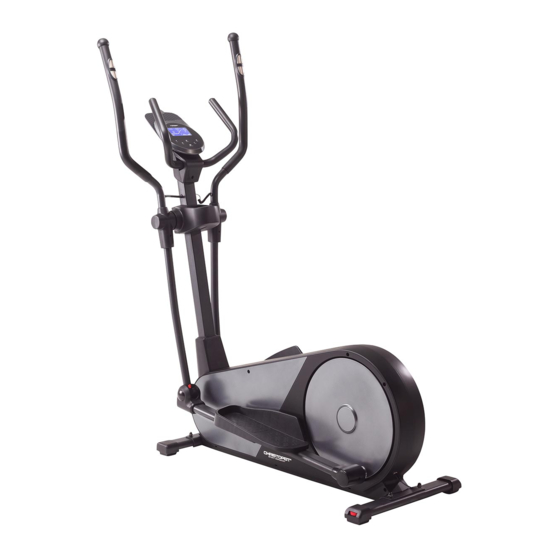
EL8000
CROSSTRAINER-ERGOMETER
Montage- und Bedienungsanleitung
Bestell-Nr.: 2229
DE
Seite: 2-15
Assembly and operating instructions
Order No.: 2229
GB
Page: 16-28
Instructions de montage et d'utilisation
F
No. de commande: 2229
Page: 29-41
Montage- en bedieningsinstructies
Bestellnr.: 2229
NL
Pagina: 42-54
1
Werbung

Verwandte Anleitungen für Christopeit Sport EL8000


Inhaltszusammenfassung für Christopeit Sport EL8000
- Seite 1 EL8000 CROSSTRAINER-ERGOMETER Montage- und Bedienungsanleitung Bestell-Nr.: 2229 Seite: 2-15 Assembly and operating instructions Order No.: 2229 Page: 16-28 Instructions de montage et d'utilisation No. de commande: 2229 Page: 29-41 Montage- en bedieningsinstructies Bestellnr.: 2229 Pagina: 42-54...
- Seite 2 INHALTSÜBERSICHT Seite Inhalt Christopeit-Sport Community Wichtige Empfehlungen und Sicherheitshinweise Montageanleitung Benutzung des Gerätes Trainingsplatzbedarf Watt-Tabelle 9-11 Computerbeschreibung Pulsmessung Achtung! Vor Benutzung APP-Konnektivität Bedienungs- Reinigung, Wartung und Lagerung anleitung lesen! Störungsbeseitigung Garantiebestimmungen Trainingsanleitung Allgemein 14-15 Stückliste - Ersatzteilliste Explosionszeichnung SEHR GEEHRTE KUNDIN, SEHR GEEHRTER KUNDE, wir gratulieren Dir zum Kauf dieses Heimsport-Trainingsgerätes und wünschen Dir viel Vergnügen damit.
- Seite 3 WICHTIGE EMPFEHLUNGEN UND SICHERHEITSHINWEISE Unsere Produkte sind grundsätzlich TÜV-GS geprüft und entsprechen damit dem aktuellen, höchsten Sicherheitsstandard. Diese Tatsache entbindet aber nicht, die nachfolgenden Grundsätze strikt zu befolgen. Das Gerät genau nach der Montageanleitung aufbauen und nur Personen wie Kinder, Invalide und behinderte Menschen sollten, die, für den Aufbau des Gerätes beigefügten, gerätespezifischen das Gerät nur im Beisein einer weiteren Person, die eine Hilfestellung Einzelteile...
- Seite 4 MONTAGEANLEITUNG Bevor Sie mit der Montage beginnen, unbedingt unsere Empfehlungen Sicherheitshinweise beachten! Entnehmen alle Einzelteile Verpackung, legen Sie diese auf den Boden und kontrollieren grob Sie die Vollzähligkeit anhand der Montagebilder. Dieses soll Ihnen den Zusammenbau des Gerätes erleichtern und schneller durchführbar machen.
- Seite 5 SCHRITT 3 Montage der Handgriffe (16), Fußhebel (42) und der Verbindungsrohre (27). 1. Die Handgriffe links und rechts (16L+16R) auf die Verbindungsrohre (27L+27R) stecken und die Bohrungen in den Rohren so ausrichten, dass sie übereinander liegen. (Achtung! Die Handgriffe müssen nach der Montage so ausgerichtet sein, dass die oberen Enden nach außen (vom Stützrohr (13) weg) gebogen sind und die Verbindungsrohre nach vorne gewölbt sind.)
- Seite 6 SCHRITT 5 Montage der Fußschalen (41) und des Haltegriffes (3). 1. Stecken Sie auf die Schrauben M8x20 (28) jeweils einen Federring (21) und eine Unterlegscheibe 8//16 (32) auf. 2. Führen Sie den Haltegriff (3) zum Stützrohr (13) und schrauben Sie mittels der Schrauben (28) den Haltegriff (3) am Stützrohr (13) fest.
- Seite 7 KONTROLLE UND INBETRIEBNAHME 1. Alle Verschraubungen Steckverbindungen ordnungsgemäße Montage und Funktion prüfen. Die Montage ist hiermit beendet. 2. Wenn alles Ordnung ist, leichten Widerstandseinstellungen mit dem Gerat vertraut machen und die individuellen Einstellungen vornehmen. Hinweis: Bitte das Werkzeug-Set und die Anleitung sorgsam aufbewahren, da diese bei ggf.
- Seite 8 TRAININGSPLATZBEDARF 2200 2200 2200 2200 1380 1380 1790 1790 2580 2580 Stellfläche in mm Trainingsfläche in mm (für Gerät) (Trainingsfläche und Sicherheitsfläche umlaufend 600mm) WATT-TABELLE U/min und Wattleistung U/min → Stufe ↓ Anmerkung: Die Leistungsanzeige in Watt wurde anhand der Umdrehungszahl der Tretachse pro Minute (UPM) und des Bremsmomentes (Nm) eingestellt.
- Seite 9 COMPUTERBESCHREIBUNG TASTEN [T-TEST] Taste: Fitnesstest [B-BODYFAT] Taste: Körperfett-Analyse [E-ENTER] Taste: Bestätigt eine Programmauswahl, ruft Eingabefunktionen auf und bestätigt diese. Durch ca. 2 sec. Drücken werden alle Vorgabewerte zurückgesetzt. ANZEIGEN [+] - [-] Tasten: Erhöht oder verringert einen Vorgabewert oder ruft in der Auswahl die nächste oder vorherige Funktion auf.(Nur [TIME] Zeit: 00:00~99:59.
- Seite 10 PROGRAMME 01: Manuelles Programm Programm 14 Programm 15 Programm 16 Das Programm 01 mittels der [+/-] Tasten auswählen und mit der Benutzer 1 Benutzer 2 Benutzer 3 [E] Taste bestätigen. Aufrufen der Vorgabemöglichkeiten [TIME] Zeit, [DISTANCE] Entfernung, [CAL] Kalorien und [P] Puls durch Drücken der [E] Taste und Einstellen der Werte mittels der [+/-] Tasten.
- Seite 11 BODYFAT-TEST: „Crosstrainer„ an. Wählen Sie dann über das Hersteller-Logo Drücken Sie die [B] Taste um direkt auf das Körperfettprogramm „Christopeit Sport„ Ihre Typbezeichnung aus um das Sportgerät 24 zu gelangen. zu verbinden. Je nach Sportgerät werden unterschiedliche Funktionen über Bluetooth von der APP erfasst, bzw. Daten ausgetauscht.
- Seite 12 REINIGUNG, WARTUNG UND LAGERUNG 1. Reinigung Benutzen Sie nur ein leicht angefeuchtetes Tuch zur Reinigung. Achtung! Benutzen Sie niemals Benzin, Verdünner oder andere aggressive Reinigungsmittel zur Oberflächenreinigung da dadurch Beschädigungen verursacht werden. Das Gerät ist nur für den privaten Heimgebrauch und zur Benutzung in Innenräumen geeignet. Halten Sie das Gerät sauber und Feuchtigkeit vom Gerät fern. 2.
- Seite 13 TRAININGSANLEITUNG ALLGEMEIN Um spürbare, körperliche und gesundheitliche Verbesserungen zu 02: Trainingspuls-Berechnen erreichen, müssen für Bestimmung erforderlichen Durch meine Ziele und Trainingsgrad passt für mich die Fettstoffwechsel- Trainingsaufwandes folgende Faktoren beachtet werden. Zone am besten. Trainingspuls = 60 bis 70% von dem Maximalpuls INTENSITÄT Trainingspuls = 190 x 0,6 [60%] Die Stufe der körperlichen Belastung beim Training muß...
- Seite 14 STÜCKLISTE - ERSATZTEILLISTE Artikel: EL8000 • Kinomap App kompatibel • Fußschalen 3-fach in der Position verstellbar Art.-Nr.: 2229 • Niveau Boden- Höhenausgleich und Transportrollen 16.08.2023 Stand der technische Daten: • Back Light LCD Display mit allen relevanten Trainingsdaten Stellmaß [cm]: L 138 x B 59 x H 166 •...
- Seite 15 Abmessung Montiert an Abb.- Nr. Bezeichnung Menge ET Nummer Abb. Nr. Unterlegscheibe 8//16 28+56 39-9962 Kreuzschlitzschraube 4x20 34+85 36-9825338-BT Fußhebelabdeckung links 34R+42 36-2229-13-BT Fußhebelabdeckung rechts 34L+42 36-2229-14-BT Innensechskantschraube M10x78 27+42 39-10055-SW Kunststofflager 14x32 36-9925516-BT Selbstsichernde Mutter 39-9981-VC Unterlegscheibe 10//19 39-9989-CR Distanzrohr 14x10x59 36-9925515-BT...
- Seite 16 CONTENTS DEAR CUSTOMER, Page Contents Important Recommendations and Safety Instructions 17-20 Assembly Instructions we congratulate you on your purchase of this home training sports Use of the device unit and hope that we will have a great deal of pleasure with it. Training space requirement Please take heed of the enclosed notes and instructions and Watt table...
- Seite 17 ASSEMBLY INSTRUCTIONS Remove all the separate parts from the packaging, lay them on the floor and check roughly that all are there on the base of the assembly steps. Please note that a number of parts are connected directly to the main frame preassembled.
- Seite 18 STEP 3 Installation of the handgrip (16) and foot rest holder (42) at connecting tubes (27). 1. Push the handgrip bars (16L+16R) onto the connecting tubes (27L+27R) and adjust the holes in the tubes so that they are aligned. (Note: The handgrip bars must be aligned after assembly so that the upper ends are inclined outwards (away from the support (13)).
- Seite 19 STEP 5 Installation of the footrests (41) and handle grip (3). 1. Put one spring washer (21) and one washer 8//16 (32) onto each screw M8x20 (28). 2. Place the handle grip (3) against the support (13) so that the holes are aligned and push the screws (28) through the holes and tighten the handle grip (3) at support (13) firmly.
- Seite 20 CHECKS 1. Check the correct installation and function of all screwed and plug connections. Installation is thereby complete. 2. When everything is in order, familiarize yourself with the machine at a low resistance setting and make your individual adjustments. Note: Please keep the tool set and the instructions in a safe place as these may be required for repairs or spare parts orders becoming necessary later.
- Seite 21 TRAINING SPACE REQUIREMENT 2200 2200 1380 1790 2580 Place requirement in mm Trainings area in mm (for product) (Training area and security area (circulating 600mm)) WATT-TABELLE RPM and Power Level. RPM → Level ↓ Note: The power consumptions (Watt) are adjusted by measuring the driving speed (min-1) of axle and the braking torque (Nm). Your equipment was tested to fulfill the requirements of its accuracy classification before shipment, If you have doubts about the accuracy, please contactwith your local retailer or send it to accredited test laboratory to ensure or calibrate it.
- Seite 22 COMPUTER KEYS [T-TEST] key: fitness test. [B-BODYFAT] key: body fat analysis. [E-ENTER] key: Confirms a program selection, calls up input functions and confirms them. All default values are reset by pressing for approx. 2 seconds. DISPLAY [+] - [-] keys: Increases or decreases a preset value or calls up the next or previous function in the selection.
- Seite 23 PROGRAMS 01: Manually program Program 14 Program 15 Program 16 Select the program 01 using the [+/-] keys and confirm with the User 1 User 2 User 3 [E] key. Call up the setting options [TIME] time, [DISTANCE] distance, [CAL] calories and [P] pulse by pressing the [E] key and setting the values using the [+/-] keys.
- Seite 24 Bluetooth heart rate belt, such user, [HEIGHT] height, [WEIGHT] weight [GENDER] gender and as the Christopeit Sport BT heart rate belt (item no.: 2209). If [AGE] age and enter your data by using the [+/-] keys. Then grab you moisten the heart rate belt a little before you put it on, the the hand pulse sensors to measure your body fat.
- Seite 25 CLEANING, CHECKS AND STORAGE 1. Cleaning Use only a less wet cloth for cleaning. Attention! Never use benzene, thinner or other aggressive cleaning agents for surface cleaning as this damage caused. The device is only for private home use and for use suitable indoors. Keep the unit clean and moisture from the device.
- Seite 26 GENERAL TRAINING INSTRUCTIONS You must consider the following factors in determining the amount of 02: Training heart rate calculation training effort required in order to attain tangible physical and health Due to my goals and training level, the fat metabolism zone benefits.
- Seite 27 PARTS LIST – SPARE PARTS LIST Type: EL8000 • Foot pedals in 3 positions adjustable • Floor level compensation and Transport rollers Order-Nr.: 2229 • Back Light LCD Display shows simultaneously: Time, Speed, 16.08.2023 Date of technical data: Distance, approx. calorie consumption, RPM, Watt and pulse...
- Seite 28 Illustr. Dimension Attached to Designation Quantity ET-Number Illustration No. Washer 8//16 28+56 39-9962 Self-tapping screw 4x20 34+85 36-9825338-BT Foot tube cap left 34R+42 36-2229-13-BT Foot tube cover right 34L+42 36-2229-14-BT Allen bolt M10x78 27+42 39-10055-SW Bushing 14x32 36-9925516-BT Nylon nut 39-9981-VC Washer 10//19...
- Seite 29 SOMMAIRE CHÈRE CLIENTE, CHER CLIENT, Page Contenu Recommandations importantes et consignes de sécurité 30-33 Instructions de montage Nous vous félicitons pour l’achat de ce cycle d’entraînement Monter, utiliser & descendre intérieur et nous vous souhaitons beaucoup de plaisir avec. Besoin d’espace de formation Veuillez respecter et suivre les indications et les instructions de Table de watts montage et d’emploi.
- Seite 30 INSTRUCTIONS DE MONTAGE Sortez toutes les pièces de l’emballage, posez-les sur le sol et contrôlez si rien ne manque en vous basant grossièrement sur la étapes de montage. Il faut tenir compte du fait que certaines pièces ont été reliées au cadre et prémontrés.
- Seite 31 ÉTAPE 3 Montage des poignées (16), des logements de pied (42) sur les tubes de communication (27). 1. Placer les poignées (16L+16R) sur les tubes de communication (27L+27R) en veillant à ce que les trous de forage des tubes soient situés les uns au-dessus des autres. (Attention! Après le montage des poignées, veillez à...
- Seite 32 ÉTAPE 5 Montage des coques des pieds (41) et poignée de maintien (3). 1. Poser une rondelle élastique bombée (21) et une rondelle 8//16 (77) sur le vis 8x20 (28). 2. Dirigez la poignée de maintien (3) vers le tube support (13) et vissez avec le vis (28).
- Seite 33 CONTRÔLE 1. Vérifier si les assemblages et connexions ont été effectués correctement et fonctionnent. Le montage est maintenant terminé. 2. Si tout est en ordre, se familiariser avec l’appareil en effectuant de légers réglages de la résistance et effectuer les réglages individuels.
- Seite 34 BESOIN D’ESPACE DE FORMATION 2200 2200 1380 1790 2580 Besoins en espace en mm Surface d’entraînement (Pour appareil) (Zone de la formation et de la zone de sécurité (tout autour 600mm)) TABLE DE WATTS RPM et puissance du niveau RPM → Niveau ↓...
- Seite 35 DESCRIPTION DE L’ORDINATEUR TOUCHES Touche [T-TEST]: test de condition physique Touche [B-BODYFAT]: analyse de la graisse corporelle Touche [E-ENTER]: Confirme une sélection de programme, appelle les fonctions d’entrée et les confirme. Toutes les valeurs par défaut sont réinitialisées en appuyant 2 secondes pendant environ.
- Seite 36 PROGRAMME 01: programme manuel Programme 14 Programme 15 Programme 16 Sélectionnez la programme 01 à l‘aide des touches [+/-] et Utilisateur 1 Utilisateur 2 Utilisateur 3 confirmez avec la touche [E]. Appelez les options de réglage [TIME] temps, [DISTANCE] la distance, [CAL] les calories et [P] pouls en appuyant sur la touche [E] et en réglant les valeurs à...
- Seite 37 Sélectionnez ensuite votre désignation de type via le logo du fabricant „Christopeit Sport“ secondes. Une fois les 60 secondes écoulées, une note de forme physique de F1 à F6 s‘affiche. (Voir le tableau sous-programme afin de connecter l‘équipement sportif. Selon l‘équipement sportif, de test de condition physique) différentes fonctions sont enregistrées par l‘APP via Bluetooth ou...
- Seite 38 NETTOYAGE, ENTRETIEN ET STOCKAGE DE L‘EXERCICE 1. Nettoyage Utilisez uniquement un chiffon humide pour le nettoyage. Respect! Ne jamais utiliser de benzène, de diluant ou autre agents de nettoyage agressifs pour le nettoyage de surface comme ce les dommages causés. L‘appareil est uniquement pour un usage domestique privé...
- Seite 39 CONSIGNES GÉNÉRALES DE FORMATION Les facteurs ci-après doivent être pris en compte pour la détermination de 01 : Impulsion maximale - calcul l’entraînement indispensable afin d’améliorer concrètement son physique Fréquence cardiaque maximale = 214 - (0,5 x âge) - (0,11 x poids) et sa santé.
- Seite 40 LISTE DES PIÈCES- LISTE DES PIÈCES DE RECHANGE Désignation: EL8000 • Pied bouche avec réglage en hauteur et roues de transport • Écran LCD rétroéclairé avec affiche: Durée, vitesse, distance, No. de commande: 2229 qui correspond plus ou moins à la dépense de calories, les 16.08.2023...
- Seite 41 Schéma Dimensions Quantité Monté sur Désignation Numéro ET N° en mm Unités schéma n° Rondelle 8//16 28+56 39-9962 Vis à tête cruciforme 4x20 34+85 36-9825338-BT Revêtement de logement de pied gauche 34R+42 36-2229-13-BT Revêtement de logement de pied droit 34L+42 36-2229-14-BT Vis à...
- Seite 42 INHOUDSOPGAVE GEACHTE KLANT Pagina Inhoud Belangrijke aanbevelingen en veiligheidsinstructies 43-46 Montagehandleiding Wij willen u van harte gelukwensen met de aanschaf van uw Opstappen, gebruiken & afstappen hometrainer en hopen dat u hier veel plezier aan zult beleven. Neem a.u.b. de instructies en aanwijzingen uit deze montage- en Training space requirement bedieningshandleiding in acht en volg deze op.
- Seite 43 MONTAGEHANDLEIDING Neem alle losse onderdelen uit de verpakking, leg deze op de grond en bruto controleer aan de hand van de montageen staps of alle onderdelen aanwezig zijn. Hierbij moet er op worden gelet dat een aantal onderdelen rechtstreeks met het onderstel zijn verbonden en voorgemonteerd zijn.
- Seite 44 STAP 3 Montage van de greepbuizen (16) en van de voet- schaalbevestiging (42) aan de verbindingsbuizen (27). 1. De greepbuizen (16L+16R) op de verbindingsbuizen (27L+27R) steken en de openingen in de buizen zo uitlijenen dat ze boven elkaar liggen. (Let op! De greepbuizen moeten na de montage zo zijn uitgelijnd dat de bovenste uiteinden naar buiten (van steunbuis (13) af) en de verbindingsbuizen naar voren zijn gebogen.)
- Seite 45 STAP 5 Montage van de voetschaalen (41) en de handgreep (3). 1. Voorzie de bouten M8x20 (28) van een verring (21) en een tussenring 8//16 (32). 2. Breng de handgreep (3) naar de steunbuis (13) zodat de gaten in een lijn liggen en steek de schroeven (28) door de gaten en ver vast de handgreep (3) aan het steunbuis (13).
- Seite 46 CONTROLE 1. Alle schroef- en stekkerverbindingen op een correcte montage en juiste werking controleren. Daarmee is de montage beëindigd. 2. Wanneer alles in orde is, met lichte weerstandsinstellingen vertrouwd raken met het apparaat en de individuele instellingen vastzetten. Opmerking: De gereedschapsset en de gebruiksaanwijzing a.u.b. zorgvuldig bewaren, omdat u ze wellicht later voor een reparatie of het bestellenvan reserveonderdelen nodig heeft.
- Seite 47 TRAINING SPACE REQUIREMENT 2200 2200 1380 1790 2580 Ruimtevereisten in mm Trainingsgebied in mm (Voor de apparaat) (Voor de apparaat-en gebruikers omringend 600mm) WATT TAFEL RPM en wattage van niveau RPM → Niveau ↓ Opmerkingen: De energieconsumptie (Watt) wordt gemeten door de trapsnelheid te meten (min-1) van de as en de torsie (Nm). Het apparaat is vóór verscheping geijkt om te voldoen aan vereisten van de accuratieclassificatie, Mocht u twijfels hebben over de accuratie, neem dan aub contact op met uw leverancier of stuur het apparaat naar een bevoegd laboratorium om te laten testen, og opnieuw te laten ijken.
- Seite 48 COMPUTER OMSCHRIJVING TOETSEN [T-TEST] toets: conditie test [B-BODYFAT] toets: lichaamsvet analyse [E-ENTER] toets: Bevestigt een programmakeuze, roept invoerfuncties op en bevestigt deze. Alle standaardwaarden worden gereset door ongeveer 2 seconden ingedrukt te houden. [+/-] toetsen: Verhoogt of verlaagt een vooraf ingestelde waarde of roept de volgende of vorige functie in de selectie op (alleen knipperende informatie kan worden gewijzigd/bevestigd).
- Seite 49 PROGRAMMA 01: Handmatig programma: Programma 14 Programma 15 Programma 16 Selecteren van het programma 01 met de [+/-] toetsen en bevestig Gebruiker 1 Gebruiker 2 Gebruiker 3 met de [E] toets. Roep de instelopties [TIME] tijd, [DISTANCE] afstand, [CAL] calorieën en [P] hartslag op door op de [E] toets te drukken en de waarden in te stellen met de [+/-] toetsen.
- Seite 50 „Crosstrainer“. Selecteer vervolgens uw Na een training met hartslagweergave in elk programma met type-aanduiding via het fabriekslogo „Christopeit Sport“ om de een stressfase aan het einde, kunt u op de [T]-knop drukken sportuitrusting aan te sluiten. Afhankelijk van de sportuitrusting en een conditietest starten.
- Seite 51 REINIGING, ONDERHOUD EN OPSLAG VAN DE HOMETRAINER 1. Reiniging Gebruik alleen een vochtige doek voor het reinigen. Let op: Gebruik nooit benzeen, thinner of andere agressieve reinigingsmiddelen voor oppervlaktereiniging als deze Schade veroorzaakt . Het apparaat is alleen voor prive gebruik en voor gebruik geschikte binnenshuis.
- Seite 52 ALGEMENE TRAININGSINSTRUCTIES U moet rekening houden met de volgende factoren bij het bepalen van 02: Training hartslagberekening Door mijn doelen en trainingsniveau past de vetstofwisselingszone het het bedrag van trainingsinspanning die nodig is om tastbare fysieke en gezondheid te bereiken voordelen. beste bij mij.
- Seite 53 STUKLIJST – LIJST MET RESERVEONDERDELEN • Stelvoeten om waterpas te zetten en transportrollen Aanduiding: EL8000 • Bedieningsvriendelijke Blue-Back-Light computer met Bestellnr.: 2229 gelijktijdige aanduiding van; tijd, snelheid, afstand, ca. 16.08.2023 Stand technische gegevens: calorieverbruik, pedaalomwentelingen, Wattage en polss- Afmetingen ca: [cm]: L 138 x B 59 x H 166 lagfrequentie.
- Seite 54 Afbeeldings- Afmetingen Aantal Gemonteerd aan Beschrijving ET-nummer stuks afbeeldingsnr. Onderlegplaatje 8//16 28+56 39-9962 Phillips schroef 4x20 34+85 36-9825338-BT Voetschalbefestiging afdekking links 34R+42 36-2229-13-BT Voetschalbefestiging afdekking rechts 34L+42 36-2229-14-BT Binnenzeskantschroef M10x78 27+42 39-10055-SW Kunstoflaager 14x32 36-9925516-BT Zelfborgende moer 39-9981-VC Onderlegplaatje 10//19 39-9989-CR Afstandsstuk 14x10x59...
- Seite 55 24Lb 24La 24Ra 24Rb 71 73...
- Seite 56 Service / Hersteller Bei Reklamationen, notwendigen Ersatzteilbestellungen oder Reparaturen wenden Sie sich bitte an unsere Service Abteilung. Top-Sports Gilles GmbH Friedrichstrasse 55 Tel.: +49 (0)2051/6067-0 Fax: +49 (0)2051/6067-44 D - 42551 Velbert info@christopeit-sport.com http://www.christopeit-sport.com © by Top-Sports Gilles GmbH D-42551 Velbert (Germany)