Inhaltsverzeichnis
Werbung
Verfügbare Sprachen
Verfügbare Sprachen
Quicklinks
Istruzioni per installazione, uso e manutenzione
Montage und Bedienungsanleitung
Instructions pour installation, utilisation et entretien
Installation, use and maintenance instructions
Instrucciones de instalación, montaje y funcionamiento
Bruciatori di nafta
I
Heizölbrenner
D
Brûleurs à fioul lourd
F
Heavy oil burners
GB
Quemadores de nafta
E
CODICE
CODE - CÓDIGO
3438964
3438965
3438966
3438967
3438968
3438969
MODELLO - MODELL
MODELE - MODEL - MODELO
PRESS 300 T/N
PRESS 300 T/N
PRESS 300 T/N
PRESS 300 T/N
PRESS 300 T/N
PRESS 300 T/N
TIPO - TYP
TYPE
468 M1
468 M1
468 M1
468 M1
468 M1
468 M1
2915844 (8) - 01/2015
Werbung
Inhaltsverzeichnis

Verwandte Anleitungen für Riello 3438964


Inhaltszusammenfassung für Riello 3438964
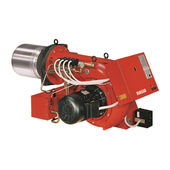
- Seite 1 Heavy oil burners Quemadores de nafta CODICE MODELLO - MODELL TIPO - TYP CODE - CÓDIGO MODELE - MODEL - MODELO TYPE 3438964 PRESS 300 T/N 468 M1 3438965 PRESS 300 T/N 468 M1 3438966 PRESS 300 T/N 468 M1...
-
Seite 3: Inhaltsverzeichnis
INDICE DESCRIZIONE DEL BRUCIATORE ..1 FUNZIONAMENTO ....11 1.1 Materiale a corredo ....1 4.1 Scelta degli ugelli . -
Seite 4: Dati Tecnici
500 mm (65° E) Pompa 470 kg/h a 25 bar DATI ELETTRICI CODICE 3438964 - 3438965 3438968 - 3438969 3438966 - 3438967 Alimentazione elettrica 3N ~ 50 Hz 400 V con neutro 3 ~ 50 Hz 230 V senza neutro... - Seite 5 FUNZIONAMENTO E POTENZA DEL BRUCIATORE Potenza termica - Portata MONOSTADIO Minima Massima kg/h kg/h 1° ugello: stadio solo di accensione 1140 1° + 2° ugello: stadio di passaggio 1140 2280 1° + 2° + 3° ugello: stadio di funzionamento 1710 3420 Potenza termica - Portata BISTADIO...
-
Seite 6: Dimensioni
DIMENSIONI Bruciatore 1000 D2776 Ottenibile con distanziale da chiedere a parte. Foratura piastra caldaia SPORGENZA TESTA DI COMBUSTIONE Per la sporgenza della testa di combustione segui- re le indicazioni fornite dal costruttore della caldaia. Per caldaie con cassa fumo anteriore eseguire una opportuna protezione in materiale refrattario sulla parte della testa sporgente in camera di com- bustione. -
Seite 7: Installazione
INSTALLAZIONE IMPIANTI ALIMENTAZIONE OLIO COMBUSTIBILE IMPIANTO AD ANELLO Per olio denso con viscosità fino a 50°E / 50°C. D2734 1 - Cisterna (riscaldata per olio denso) 6 - Bruciatore (con kit per olio denso cod. 3000721) 2 - Filtro (con resistenza per olio > 7°E / 50°C) 7 - Regolatore di pressione 3 - Pompa di trasferimento 8 - Filtro (con resistenza per olio >... -
Seite 8: Impianto Elettrico
IMPIANTO ELETTRICO DEL BRUCIATORE VERSIONE AD AVVIAMENTO DIRETTO (eseguito in fabbrica) D2618 COLLEGAMENTI SONDA SCHEMA AL TERMOREGOLATORE COMMUTATORE D2738 D2737 CMV Contattore motore ventilatore Sonda PT100 Contattore preriscaldatore Trasformatore d’accensione Commutatore Terra bruciatore Fotoresistenza Termoregolatore Segnalazioni di 1° stadio Termostato min. Segnalazioni di 2°... - Seite 9 VERSIONE AD AVVIAMENTO STELLA - TRIANGOLO (eseguito in fabbrica) D2624 COLLEGAMENTI SONDA SCHEMA AL TERMOREGOLATORE COMMUTATORE D2738 D2737 Contattore preriscaldatore Sonda PT100 Commutatore Trasformatore d’accensione Fotoresistenza Terra bruciatore Segnalazioni di 1° stadio Termoregolatore Segnalazioni di 2° stadio Termostato min. Segnalazioni di 3° stadio Termostato max.
- Seite 10 AVVIATORE STELLA - TRIANGOLO D2049 Fusibili circuito di potenza Fusibili circuito di comando Relé termico: tarare a 10,2A per 400V tarare a 17,6A per 230V KL1 Contattore di linea KS1 Contattore di stella Temporizzatore (tarare a 10 sec.) KT1 Contattore di triangolo Morsettiera Sezionatore con blocco porta 5844...
-
Seite 11: Collegamenti Elettrici
COLLEGAMENTI ELETTRICI ALLA MORSETTIERA VERSIONE AD AVVIAMENTO DIRETTO (a cura dell’installatore) D2619 230V 400V A A gG/gL B A gG/gL C mm D mm Segnalazione di blocco a distanza Telecomando di limite Acceso-spento manuale (facoltativo) Telecomando di sicurezza MB Morsettiera bruciatore Termostato di 2°... - Seite 12 VERSIONE AD AVVIAMENTO STELLA - TRIANGOLO (a cura dell’installatore) D2625 230V 400V A A gG/gL B mm C mm D mm Segnalazione di blocco a distanza Allarme alta temperatura olio Segnalazione di blocco motore Telecomando di limite Acceso-spento manuale (facoltativo) Telecomando di sicurezza MA Morsettiera avviatore Termostato di 2°...
-
Seite 13: Funzionamento
FUNZIONAMENTO SCELTA DEGLI UGELLI Ugello Portata totale Stabilire per prima la massima portata desiderata con tutti e GPH 60° kg/h 1°+2°+3° tre gli ugelli funzionanti. 1° 2° 3° 25 bar 28 bar Sulla base della portata massima scegliere, nella tabella A, la terna di ugelli necessaria. -
Seite 14: Regolazione Testa Di Combustione
REGOLAZIONE TESTA DI COMBUSTIONE kg/h D2773 Infine, sulla base della portata massima ricavare, nel dia- gramma C, la regolazione della testa di combustione. La regolazione si effettua ruotando la vite A, fino a che la tacca, rilevata dal diagramma, collima con il piano della bussola B. -
Seite 15: Regolazione Temperatura Di Polverizzazione
REGOLAZIONE TEMPERATURA DI POLVERIZZAZIONE Termostati di regolazione - di minima - di massima Il termostato di regolazione elettronico, attraverso una sonda PT 100 immersa nel collettore di mandata dell’olio combustibile regola la temperatura di polverizzazione. (Per una corretta polverizzazione vedere diagram- ma sottoriportato temperatura/viscosità). -
Seite 16: Programma Di Avviamento
PROGRAMMA DI AVVIAMENTO Blocco per mancata accensione Normale Termostato Motore Trasf. d’accensione Prelavaggio Valvola 1 fiamma Valvola 2 fiamma Valvola 3 fiamma Spia di blocco D2848 Taratura di fabbrica: 20 s. D3211 Questo tempo determina la temperatura della nafta all’accensione; può essere re- golato, in funzione della viscosità... -
Seite 17: Diagnostica Programma Di Avviamento
DIAGNOSTICA PROGRAMMA DI AVVIAMENTO Durante il programma di avviamento, le indicazioni sono esplicate nella seguente tabella: TABELLA CODICE COLORE Sequenze Codice colore Preventilazione ● ● ● ● ● ● ● ● ● ● ● Fase di accensione ● ❍ ● ❍ ● ❍ ● ❍ ● ❍ ● Funzionamento con fiamma ok ❑... -
Seite 19: Beschreibung Des Brenners
INHALT BESCHREIBUNG DES BRENNERS ..1 BETRIEB ......11 1.1 Mitgeliefertes Zubehör ....1 4.1 Wahl Der Düsen . -
Seite 20: Technische Angaben
/s (65° E) Pumpe 470 kg/h bei 25 bar ELEKTRISCHE DATEN CODE 3438964 - 3438965 3438968 - 3438969 3438966 - 3438967 Spannung - Drehstrom 3N ~ 50 Hz 400 V mit Nulleiter 3 ~ 50 Hz 230 V ohne Nulleiter... -
Seite 21: Betriebsweise Und Leistung Des Brenners
BETRIEBSWEISE UND LEISTUNG DES BRENNERS Leistung - Durchsatz EINSTUFIGER Min. Max. kg/h kg/h 1. Düse: nur Anfahr Stufe 1140 1. + 2. Düse: Übergang Stufe 1140 2280 1. + 2. + 3. Düse: Düse: Betrieb Stufe 1710 3420 Leistung - Durchsatz ZWEISTUFIGER Min. -
Seite 22: Abmessungen
ABMESSUNGEN Brenner 1000 D2776 Mit Hilfe des Distanzstückes auf Anfrage. Löcher in der kesselplatte BRENNERKOPFÜBERSTAND Was den Brennerkopfüberstand anlangt müs- sen die Vorschriften des Kesselherstellers be- achtet werden. Bei Kesseln mit vorderer Rauchkammer müss der Teil des Kopfes, welcher in den Feuerraum hineinragt mit hitzebeständigem Material ge- schützt werden. -
Seite 23: Installation
INSTALLATION BRENNSTOFFZUFÜHRUNG RINGLEITUNG Für dickflüssiges Öl mit einer Viskosität von 50°E/50°C. D2734 1 - Tank (für dickflüssiges Öl erwärmt) 6 - Brenner (mit Kit für dickflüssiges Öl Best. Nr. 3000721) 2 - Filter (mit Widerstand für Öl >7°E/50°C) 7 - Druckregler 3 - Förderpumpe 8 - Filter (mit Widerstand für Öl >7°E/50°C) 4 - Druckmesser (zur Kontrolle) -
Seite 24: Elektrisches Verdrahtungsschema
ELEKTRISCHES VERDRAHTUNGSSCHEMA DIREKTER ANLAUF (in der Fabrik fertig montiert) D2618 ANSCHLUSS VON FÜHLER KOMMUTATOR AN DEN ELEKTRONISCHEN THERMOSTAT D2738 D2737 CMV Motorkontaktgeber Luftklappenstellmotor Kontaktgeber der Heizwinderstande Fühler PT100 Kommutator Zündtransformator Fotowinderstand Brenner-erdung Signale der 1. Stufe Elektronischer Thermostat Signale der 2. Stufe Thermostat min. - Seite 25 STERN-DREIECK ANLAUF (in der Fabrik fertig montiert) D2624 ANSCHLUSS VON FÜHLER KOMMUTATOR AN DEN ELEKTRONISCHEN THERMOSTAT D2738 D2737 Kontaktgeber der Heizwinderstande Fühler PT100 Kommutator Zündtransformator Fotowinderstand Brenner-erdung Signale der 1. Stufe Elektronischer Thermostat Signale der 2. Stufe Thermostat min. Signale der 3. Stufe Thermostat max.
- Seite 26 STERN-DREIECK MOTORSTARTER D2049 Leistungskreissicherungen Steurungskreissicherungen Thermisches Relais: muss bei 400V = 10,2A und muss bei 230V = 17,6A eingestellt werden KL1 Netz-kontkigeber KS1 Stern-kontakigeber Zeitrelais für Stern-Dreieck (bei 10s einstellen) KT1 Dreieck-kontakigeber Klemmbrett-starter Tursperretrennschalter 5844...
-
Seite 27: Elektrische Anschlüsse An Der Klemmeleiste
ELEKTRISCHE ANSCHLÜSSE AN DER KLEMMELEISTE DIREKTER ANLAUF (vom Installateur auszuführen) D2619 230V 400V A A gG/gL B A gG/gL C mm D mm Storungs Femmeldung Grenzwert-Fernsteuerung Fakultative Hand-Brennerabschaltung Sicherheit-Fernsteuerung MB Brenner-Klemmleiste 2. Stufe Thermostat Entriegelungstaste 3. Stufe Thermostat SA Ölhochtemperaturalarm BEMERKUNG: Zur Prüfung der Störabschaltung die Abdeckung der Frontplatte entfernen und die Fotozelle abdunkeln. - Seite 28 ELEKTRISCHE ANSCHLÜSSE AN DER KLEMMELEISTE STERN-DREIECK ANLAUF (vom Installateur auszuführen) 2625 230V 400V A A gG/gL B mm C mm D mm Störungs Ferneldung SA Ölhochtemperaturalarm Störungs Motor meldung Grenzwert-Fernsteuerung Fakultative Hand-Brennerabschaltung Sicherheit-Fernsteuerung MA Anlauf-Klemmleiste 2. Stufe Thermostat MB Brenner-Klemmleiste 3.
-
Seite 29: Betrieb
BETRIEB WAHL DER DÜSEN Düsen Gesamtdurchsatz Zuerst den gewünschten max. Durchsatz bei Betrieb aller GPH 60° kg/h 1. + 2. + 3. drei Düsen festlegen. 25 bar 28 bar Anhand des max. Durchsatzes und der Tabelle A die an- 8,00 8,00 8,00 gebrachten 3 Düsen wählen. -
Seite 30: Einstellung Des Brennerkopfes
EINSTELLUNG DES BRENNERKOPFES kg/h D2773 Schliesslich die Einstellung des Brennerkopfes auf- grund des max. Durchsatzes mit Hilfe des Diagrammes C feststellen. Die Einstellung erfolgt, indem die Schraube A so weit gedrehtwird, bis die im Diagramm angegebene Einstell- zahl mit der Ebene der Buchse B übereinstimmt. Einstellzahl 6 D2743 LUFTKLAPPENEINSTELLUNG... -
Seite 31: Einstellung Der Zerstäubungstemperatur
EINSTELLUNG DER ZERSTÄUBUNGSTEMPERATUR Einstellbarer Temperaturregler - der min. Temp. und max. Temp. Der einstellbare elektronische Temperaturregler steuert über einen, in das Vorlaufsammelrohr des Heizöls eingetauchten PT 100 Fühler die Zerstäubungstemperatur (Kennlinie der korrekten Zerstäubung nachstehen- dem Temperatur/Viskosität Diagramm entnehmen). Fühler Tempereturregler /s °E Thermometer D2746... -
Seite 32: Betriebsablauf
BETRIEBSABLAUF Normal Störabschaltung wegen Nichtzündung Thermostat Motor Zündtransformator Vorspülzeit 1. Stufe Ventil 2. Stufe Ventil 3. Stufe Ventil Störanzeiger D2848 Werkseitige Einstellung: 20 s. D3211 Diese Zeit bestimmt die Heizöltemperatur bei der Zündung; sie kann je nach Brenn- stoffviskosität vom Zeitschalter 22) (Abb. 1) eingestellt werden. -
Seite 33: Diagnostik Betriebsablauf
DIAGNOSTIK BETRIEBSABLAUF Die Bedeutung der verschiedenen Anzeigen während des Anlaufprogramms ist in folgender Tabelle erklärt: FARBCODETABELLE Sequenzen Farbcode Vorspülung ● ● ● ● ● ● ● ● ● ● ● Zündung ● ❍ ● ❍ ● ❍ ● ❍ ● ❍ ● Betrieb mit Flamme OK ❑... -
Seite 35: Burner Description
INDEX BURNER DESCRIPTION ....1 WORKING ......11 1.1 Burner equipment . -
Seite 36: Technical Data
/s (65° E)with kit Pump 470 kg/h at 25 bar ELECTRICAL DATA CODE 3438964 - 3438965 3438968 - 3438969 3438966 - 3438967 Electrical supply 3N ~ 50 Hz 400 V with neutral 3 ~ 50 Hz 230 V without neutral... - Seite 37 OPERATION AND EFFICIENCY OF THE BURNER Thermal power - Output Minimum Maximum STAGE kg/h kg/h 1140 nozzle: ignition phase 1140 2280 nozzle: intermediate phase 1710 3420 nozzle: operation phase Thermal power - Output Minimum Maximum STAGE kg/h kg/h 1140 nozzle: ignition phase 1140 2280...
-
Seite 38: Overall Dimensions
OVERALL DIMENSIONS Burner 1000 D2776 It is possible with a spacer, upon request. Boiler front plate drilling COMBUSTION HEAD PROJECTION For the combustion head projection carefully follow the boiler manufacturer indications. A proper protection with refractory material on the combustion head projecting into the combustion chamber shall be made, when boilers with frontal smoke box are used. - Seite 39 HEAVY OIL SUPPLY LINE RING SUPPLY LINE For heavy oil with viscosity up to 50°E/50°C. D2734 1 - Tank (heated for heavy oil) 6 - Burner (provided with kit for heavy oil code no. 3000721) 2 - Filter (with resistance for oil > 7°E/50°C) 7 - Pressure adjuster 3 - Forwarding pump 8 - Filter (with resistance for oil >...
-
Seite 40: Electrical System
ELECTRICAL SYSTEM DIRECT START-UP (carried out by the factory) D2618 PRE-HEATER CONNECTION COMMUTATOR PROBE TO ELECTRONIC THERMOSTAT D2738 D2737 CMV Fan motor contact maker Air-damper actuator Resistor contact maker Probe PT100 Commutator Ignition transformer Photoresistence Burner earth Lamps for 1 stage Electronic thermostat Lamps for 2... - Seite 41 STAR-TRIANGLE START-UP (carried out by the factory) D2624 PRE-HEATER CONNECTION COMMUTATOR PROBE TO ELECTRONIC THERMOSTAT D2738 D2737 Resistor contact maker Ignition transformer Commutator Burner earth Photoresistence Electronic thermostat Lamps for 1 stage Minimal thermostat Lamps for 2 stage Maximal thermostat Lamps for 3 stage Timer...
- Seite 42 STAR-TRIANGLE STARTER D2049 Power line fuses Control devices fuse Thermal relay to be set at 10.2A for 400V or at 17.6A for 230V KL1 Line contact maker KS1 Star contact maker Timer relay for switching from star to delta (factory calibration at 10s) KT1 Delta contact maker Starter terminal strip Disconnecting switch with interlock...
- Seite 43 ELECTRICAL CONNECTIONS TO THE BURNER TERMINAL STRIP DIRECT START-UP (to be carried out by the installer) D2619 230V 400V A A gG/gL B A gG/gL C mm D mm Remote lock-out signal Limit control device system Optional switch on-off burner Safety control device system MB Burner terminal strip Load control system for 2...
- Seite 44 STAR-TIRANGLE START-UP (to be carried out by the installer) D2625 230V 400V A A gG/gL B mm C mm D mm Remote lock-out signal SA High temperature oil alarm Motor trip signal Limit control device system Optional switch on-off burne Safety control device system MA Start-up terminal strip Load control system for 2...
-
Seite 45: Pump Pressure
WORKING CHOICE OF NOZZLES Nozzles Total output First of all state the maximum output required with all three GPH 60° kg/h 1 nozzles in operation. 25 bar 28 bar On the base of the maximum output choose, from table A, three related nozzles. -
Seite 46: Combustion Head Adjustment
COMBUSTION HEAD ADJUSTMENT kg/h D2773 On the base of the maximum delivery detect, from dia- gramm C, the combustion head adjustment. The adjustment should be made by turning the screw A till the set-point (see diagram) is on the line with the washer B. - Seite 47 SPRAY TEMPERATURE ADJUSTMENT Thermostat for adjustment - maximum value - minimum value Electronic adjustment thermostat by means of information relayed from a PT100 probe immersed in the oil in the delivery manifold, the thermostat adjusts spray temperature. (The correct conditions for fuel spray are shown in the temperature/viscosity graph below).
-
Seite 48: Burner Start-Up Cycle
BURNER START-UP CYCLE Normal Lock-out because no ignition Thermostat Motor Ignition transformer Pre-purge flame valve flame valve flame valve Lock-out lamp D2848 Factory setting: 20 s. D3211 This time determines the heavy oil tempera- ture at ignition. It can be adjusted, accord- ing to the fuel’s viscosity, by the timer 22) (Fig. - Seite 49 BURNERS START-UP CYCLE DIAGNOSTICS During start-up, indication is according to the followin table: COLOUR CODE TABLE Sequences Colour code Pre-purging ● ● ● ● ● ● ● ● ● ● ● Ignition phase ● ❍ ● ❍ ● ❍ ● ❍ ● ❍ ● Operation, flame ok ❑...
-
Seite 51: Description Du Bruleur
SOMMAIRE DESCRIPTION DU BRULEUR ..1 FONCTIONNEMENT....11 Matériel fourni ......1 Choix des gicleurs . -
Seite 52: Donnees Techniques
500 mm /s (65° E) Pompe 470 kg/h à 25 bar DONNÉES ÉLECTRIQUES CODE 3438964 - 3438965 3438968 - 3438969 3438966 - 3438967 Alimentation électrique 3N ~ 50 Hz 400 V avec neutre 3 ~ 50 Hz 230 V sans neutre... - Seite 53 FONCTIONNEMENT ET PUISSANCE DU BRULEUR Puissance thermique - Débit ère Min. Max. ALLURE kg/h kg/h ère 1140 gicleur: stade d’allumage ère ème 1140 2280 gicleur: stade de passage ère ème ème 1710 3420 gicleur: stade de fonctionnement Puissance thermique - Débit ème Min.
-
Seite 54: Dimensions
DIMENSIONS Brûleur 1000 D2776 Possible avec une entretoise sur demande. Perçage plaque chaudière PROEMINENCE TETE DE COMBUSTION Pour la proéminence de la tête de combustion, suivre les indications données par le fabricant de la chaudière. Pour les chaudières avec boîte à fumée anté- rieure, exécuter une protection appropriée avec matériel refractaire sur la partie de la tête proé- minente en chambre de combustion. -
Seite 55: Installation
INSTALLATION INSTALLATION TUYAUTERIS FUEL INSTALLATION EN BOUCLE Pour fuel lourd avec viscosité jusqu’à 50°E/50°C. D2734 1 - Cuve (réchauffée pour fuel lourd) 6 - Brûleur (avec kit pour fuel lourd code 3000721) 2 - Filtre (avec résistance pour fuel > 7°E/50°C) 7 - Régulateur de pression 3 - Pompe de transfert 8 - Filtre (avec résistance pour fuel >... -
Seite 56: Installation Électrique
INSTALLATION ELECTRIQUE DU BRULEUR DEMARRAGE DIRECT (exécuté en usine) D2618 BRANCHEMENT DE LA COMMUTATEUR SONDE AU THERMOSTAT ELECTRONIQUE D2738 D2737 CMV Contacteur pour moteur Servomoteur Contacteur pour resistences Sonde PT100 Commutatuer Transformateur d’allumage Cellule photoresistance Terre brûleur ère Indication de 1 allure Thermostat electronique ème... - Seite 57 DEMARRAGE ETOILE-TRIANGLE (exécuté en usine) D2624 BRANCHEMENT DE LA COMMUTATEUR SONDE AU THERMOSTAT ELECTRONIQUE D2738 D2737 Contacteur pour resistences Sonde PT100 Commutatuer Transformateur d’allumage Cellule photo-résistance Terre brûleur ère Indication de 1 allure Thermostat électronique ème Indication de 2 allure Thermostat min.
- Seite 58 DEMARREUR ETOILE-TRIANGLE D2049 Fusée du circuit triphase Fusée du circuit de control Relais thermique: regulier à 10,2A pour 400V regulier à 17,6A pour 230V KL1 Contacteur de ligne KS1 Contacteur de étoile Temporisateur pour étoile/triangle (tarer a 10s) KT1 Contacteur de triangle Porte-bomes demarreur Sectionneur avec bloc porte 5844...
-
Seite 59: Raccordements Électriques
RACCORDEMENTS ELECTRIQUES AU BORNIER DEMARRAGE DIRECT (réalisés par l’installateur) D2619 230V 400V A A gG/gL B A gG/gL C mm D mm Signalisation blocage brûleur à distance Télécommande de limite Arret-demarrage manuel (facultatif) Télécommande de sécurité ème MB Bornier brûleur Télécommande de 2 allure ème... - Seite 60 DEMARRAGE ETOILE-TRIANGLE (réalisés par l’installateur) D2625 230V 400V A A gG/gL B mm C mm D mm Signalisation blocage brûleur à distance SA Alarme de haute température huile combustible Signalisation de blocage moteur Télécommande de limite Arret-demarrage manuel (facultatif) Télécommande de sécurité ème MA Porte-bornes demarrage Télécommande de 2...
-
Seite 61: Fonctionnement
FONCTIONNEMENT CHOIX DES GICLEURS Gicleurs Débit total kg/h Déterminer d’abord le débit maximum désiré, avec les 3 ère ème ème GPH 60° gicleurs en fonctionnement. ère ème ème 25 bar 28 bar Sur la base du débit maximum, choisir dans le tableau A, 8,00 8,00 8,00... -
Seite 62: Réglage Tête De Combustion
REGLAGE TETE DE COMBUSTION kg/h D2773 Sur la base du débit maximum, rechercher, dans le diagramme C, le réglage de la tête de combustion. Pour le réglage il faut tourner la vis A jusqu’à ce que l’encoche indiquée par le diagramme correspond au plan du fourreau B. -
Seite 63: Réglage De La Temperature De Pulverisation
REGLAGE DE LA TEMPERATURE DE PULVERISATION Thermostat de réglage - de minimum - de maximum Le thermostat de régulation électronique, par l’intermédiaire d’une sonde PT100 immergée dans le col- lecteur de refoulement de l’huile, règle la température de pulvérisation. (Pour une pulvérisation correcte, ré- férez-vous au diagramme température/viscosité... -
Seite 64: Cycle De Démarrage
CYCLE DE DEMARRAGE Normal Mise en sécurité par défaut d’allumage Thermostat Moteur Transf. d’allumage Prélavage ère Vanne 1 allure ème Vanne 2 allure ème Vanne 3 allure Signalisation sécurité 2848 Réglage d’usine: 20 s. D3211 Cette durée détermine la température du mazout au démarrage;... -
Seite 65: Diagnostic Cycle De Démarrage
DIAGNOSTIC CYCLE DE DÉMARRAGE Pendant le programme de démarrage, les indications sont expliqées dans le tableau suivant: TABLEAU CODE COULEUR Séquences Code couleur Préventilation ● ● ● ● ● ● ● ● ● ● ● Phase d’allumage ● ❍ ● ❍ ● ❍ ● ❍ ● ❍ ● Fonctionnement avec flamme ok ❑... -
Seite 67: Descripción Del Quemador
ÍNDICE DESCRIPCIÓN DEL QUEMADOR ..1 FUNCIONAMIENTO ....11 Material suministrado en dotacíon ..1 Selección de las boquillas . -
Seite 68: Datos Técnicos
500 mm (65° E) Bomba 470 kg/h a 25 bar DATOS ELÉCTRICAS CÓDIGO 3438964 - 3438965 3438968 - 3438969 3438966 - 3438967 Alimentación eléctrica 3N ~ 50 Hz 400 V con neutro 3 ~ 50 Hz 230 V sin neutro... - Seite 69 FUNCIONAMIENTO Y POTENCIA DEL QUEMADOR Potencia térmica - Caudal 1 LLAMA Mínima Máxima kg/h kg/h 1ª boquilla: llama sólo de encendido 1140 1ª + 2ª boquilla: llama de paso 1140 2280 1ª + 2ª + 3ª boquilla: llama de funcionamiento 1710 3420 Potencia térmica - Caudal...
-
Seite 70: Campo De Trabajo
DIMENSIONES Quemador 1000 D2776 Obtenible con distanciador a pedir por separado. Perforación de la placa caldera SALIENTE CABEZAL DE COMBUSTIÓN Para el saliente del cabezal de combustión siga las indicaciones suministradas por el fabricante de la caldera. Para calderas con caja de humos delantera, reali- ce una protección adecuada de material refracta- rio en la parte saliente del cabezal en la cámara de combustión. - Seite 71 INSTALACIÓN INSTALACIONES ALIMENTACIÓN ACEITE COMBUSTIBLE INSTALACIÓN ANILLO Para aceite denso con viscosidad de hasta 50°E / 50°C. D2734 1 - Depósito (calentado para aceite denso) 6 - Quemador (con kit para aceite denso cód. 3000721) 2 - Filtro (con resistencia para aceite > 7°E / 50°C) 7 - Regulador de presión 3 - Bomba de transferencia 8 - Filtro (con resistencia para aceite >...
- Seite 72 INSTALACIÓN ELÉCTRICA DEL QUEMADOR VERSIÓN CON ARRANQUE DIRECTO (realizado en fábrica) D2618 CONEXIONES DE LA SONDA ESQUEMA AL TERMORREGULADOR CONMUTADOR D2738 D2737 CMV Contactor motor ventilador Sonda PT100 Contactor precalentador Transformador de encendido Conmutador Tierra del quemador Fotorresistencia Termorregulador Señalizaciones de 1ª llama Termostato mín.
- Seite 73 VERSIÓN CON ARRANQUE ESTRELLA - TRIÁNGULO (realizado en fábrica) D2624 CONEXIONES DE LA SONDA ESQUEMA AL TERMORREGULADOR CONMUTADOR D2738 D2737 Contactor precalentador Sonda PT100 Conmutador Transformador de encendido Fotorresistencia Tierra del quemador Señalizaciones de 1ª llama Termorregulador Señalizaciones de 2ª llama Termostato mín.
- Seite 74 ARRANCADOR ESTRELLA - TRIÁNGULO D2049 Fusibles circuito de potencia Fusibles circuito de mando Relé térmico: regular a 10,2A para 400V regular a 17,6A para 230V KL1 Contactor de línea KS1 Contactor de estrella Temporizador (regular en 10 seg.) KT1 Contactor de triángulo Regleta de conexiones Interruptor con bloqueo de la puerta 5844...
- Seite 75 CONEXIONES ELÉCTRICAS A LA REGLETA DE CONEXIONES VERSIÓN CON ARRANQUE DIRECTO (a cargo del instalador) D2619 230V 400V A A gG/gL B A gG/gL C mm D mm Señalización de bloqueo a distancia Telemando de límite Encendido-apagado manual (opcional) Telemando de seguridad MB Regleta de conexiones quemador Termostato de 2ª...
- Seite 76 VERSIÓN CON ARRANQUE ESTRELLA - TRIÁNGULO (a cargo del instalador) D2625 230V 400V A A gG/gL B mm C mm D mm Señalización de bloqueo a distancia Alarma alta temperatura aceite Señalización de bloqueo motor Telemando de límite Encendido-apagado manual (opcional) Telemando de seguridad MA Regleta de conexiones arrancador Termostato de 2ª...
- Seite 77 FUNCIONAMIENTO SELECCIÓN DE LAS BOQUILLAS Boquilla Caudal total Establecer primero el caudal máximo deseado con las tres GPH 60° kg/h 1 boquillas en funcionamiento. 25 bar 28 bar En base al caudal máximo elegir, en la tabla A, las tres bo- quillas necesarias.
- Seite 78 REGULACIÓN CABEZAL DE COMBUS- kg/h D2773 TIÓN Finalmente, en base al caudal máximo obtener, en el dia- grama C, la regulación del cabezal de combustión. La regulación se realiza girando el tornillo A, hasta que la muesca, evidenciada en el diagrama, coincide con el plano del casquillo B.
- Seite 79 REGULACIÓN TEMPERATURA DE PULVERIZACIÓN Termostatos de regulación - de mínima - de máxima El termostato de regulación electrónico, mediante una sonda PT 100 sumergida en el colector de alimenta- ción del aceite combustible regula la temperatura de pulverización. (Para una pulverización correcta, véase el diagrama a continuación temperatura/viscosidad).
- Seite 80 PROGRAMA DE ARRANQUE Bloqueo por falta de encendido Normal Termóstato Motor Transf. encendido Prelavado Válvula 1 llama Válvula 2 llama Válvula 3 llama Testigo de bloqueo D2848 Calibración de fábrica: 20 seg. D3211 Este tiempo determina la temperatura de la nafta en el encendido; puede regularse, según la viscosidad del combustible, des- de el temporizador 22) (Fig.
- Seite 81 DIAGNÓSTICO DEL PROGRAMA DE ARRANQUE Durante el programa de arranque, en la siguiente tabla se indican las explicaciones: TABLA CÓDIGO COLOR Secuencias Código color Pre-ventilación ● ● ● ● ● ● ● ● ● ● ● Fase de encendido ● ❍ ● ❍ ● ❍ ● ❍ ● ❍ ● Funcionamiento con llama ok ❑...
- Seite 84 RIELLO S.p.A. I-37045 Legnago (VR) Tel.: +39.0442.630111 http:// www.riello.it http:// www.riello.com Con riserva di modifiche - Änderungen vorbehalten! - Sous réserve de modifications - Subject to modifications - Con la posibilidad de modificación...