Inhaltsverzeichnis
Werbung
Verfügbare Sprachen
Verfügbare Sprachen
Quicklinks
en
Swing Gate Operator Installation Manual*
fr
Manuel d'installation de l'opérateur de porte battante
nl
Installatiehandleiding draaihekaandrijving
de
Installationshandbuch für Drehtorantriebe
cs
Instalační manuál pro obsluhu křídlové brány
sk
Inštalačný manuál k pohonu krídlovej brány
* For GB (UK, NI) specific information on national regulations and requirements
see English part of the manual.
CHLA250EVC
Werbung
Inhaltsverzeichnis

Verwandte Anleitungen für Chamberlain CHLA250EVC


Inhaltszusammenfassung für Chamberlain CHLA250EVC
- Seite 1 CHLA250EVC Swing Gate Operator Installation Manual* Manuel d‘installation de l‘opérateur de porte battante Installatiehandleiding draaihekaandrijving Installationshandbuch für Drehtorantriebe Instalační manuál pro obsluhu křídlové brány Inštalačný manuál k pohonu krídlovej brány * For GB (UK, NI) specific information on national regulations and requirements...
-
Seite 2: Inhaltsverzeichnis
TABLE OF CONTENTS NOTE:The original installation and operating instructions were compiled in English. Any other available language is a translation of the original English version. 1. SAFETY INSTRUCTIONS AND INTENDED USE......................................2 2. DELIVERY SCOPE..............................................4 3. TOOLS NEEDED.................................................4 4. OVERVIEW OF GATE OPERATOR..........................................4 5. -
Seite 3: Safety Instructions And Intended Use
(EU: EN 13241, EN12604, EN 12453; GB (UK, NI) BS EN 13241, BS EN12604, BS EN 12453). Only Chamberlain and approved accessories may be connected to the drive. Incorrect installation and/or failure to comply with the following instructions may result in serious personal injury or damage to property. - Seite 4 1. SAFETY INSTRUCTIONS AND INTENDED USE During operation, the gate should not under any circumstances obstruct public path ways and roads (public area). When using tools and small parts to install or carry out repair work on a gate exercise caution and do not wear rings, watches or loose clothing. To avoid serious personal injury due to entrapments, remove any locking device fitted to the gate in order to prevent damage to the gate.
-
Seite 5: Delivery Scope
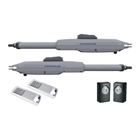
2. DELIVERY SCOPE CHLA250EVC (2 x motor units) CHLA250EVC Post Mounting Gate Mounting Pin (4x) Clevis Pin (4x) Control Box Remote Photocell Release Key (4x) Installation Bracket (2x) Bracket (2x) Control (2x) Manual 3. TOOLS NEEDED 13, 14 mm 5 mm 4. -
Seite 6: Mechanical Installation
All crushing points must be secured by an entrapment protection according to EU: EN 12453, EN 60335-2-103; GB (UK, NI): BS EN 12453, BS EN 60335-2-103. Example installation Gate Post Gate Gate Bracket Table 1: CHLA250EVC with external hardstop, using max 300 mm travel Gate Operator Post Bracket Gate leaf bracket extension shall be co- n.a. -
Seite 7: Post Bracket Installation
3. Bring gate leaf to the CLOSED position. NOTE: The system must operate with: CHLA250EVC only with external gate hard stops in both directions. 4.1 Installation with external gate hard stops: (gate hard stops already installed): a. Pull out the tube completely and make 1 complete turn of the tube in clockwise direction see (picture 4.1.a). -
Seite 8: Hardstop Installation
5. MECHANICAL INSTALLATION 4.1.a Spirit level 1 x 360° 1115 mm 4.1.b 5.5 Hardstops Installation Hardstop 90° Example for 90° opening, please see table on page 5 for other settings! Hardstop... -
Seite 9: Emergency Release Mechanism
5. MECHANICAL INSTALLATION 5.6 Emergency Release Mechanism To disengage the release mechanism turn protection cap to the side, enter the key and turn it 90°. Pull the clutch up. To re-engage the release meachanism, push the clutch down and turn the key 90°. NOTE: Same procedure applies for left and right hand units. -
Seite 10: Wiring Diagram
6. WIRING DIAGRAM AC 230V IN IR 3 IR 2 IR 1 EXAMPLE 8.2K BATTERY 24V BAT EDGE IR SENSOR COMMAND E-LK SPEC SE SE GND IR2 IR1 IN3 IN2 IN1 24V external accessories Examples: outdoor receiver EXAMPLE 24VDC SYNC STBY UART LIMIT-SW... -
Seite 11: Programming
7. PROGRAMMING 7.1 Display, Programming Buttons and Function Setting 2 digit LED display Programming buttons function (4 buttons): Button Function program / delete remote controls and specific functions enter programming mode, select function and save LED spot Navigate through the menu and change the value on display Function and programmed values are shown on LED display. -
Seite 12: Wing Movement Direction
7. PROGRAMMING 7.3 Wing Movement Direction Before programming, move the gate manually in the middle position and re-engage release mechanism (see page 8). Press and hold the “–“ button on the control board and ensure that the motors are moving in CLOSE direction. If correct, immediately let go of the “-“ button and gate stops. -
Seite 13: Stand-By Mode
7. PROGRAMMING NOTE: To stop Learning phase press “S” button. The Learning process will be interrupted, “LE” will flash on LED display. After 5 seconds “LL” will appear on display indicating readiness to start Learning phase again. 5 sec. If Learning process was not completed, it needs to be re-done. ATTENTION: Learning phase must be completed to enable operation. -
Seite 14: Programming And Erasing Of Remote Controls, Radio Accessories And Myq Devices
After having installed and registered correctly you may now test the following features: open or close the gate, request status GATE OPEN or GATE CLOSED. For more functions see www.chamberlain.eu Erase radio control devices (transmitters, wireless wall controls, wireless keypads): Press and hold “S”... -
Seite 15: Advanced Settings
7. PROGRAMMING 7.7 Advanced Settings Herewith you start with Advanced Settings. 7.7.1 Overview Advanced Settings Function Function Transmitter Flashing Light IR1 photocell Pre-Flashing IR2 photocell Special contact IR3 photocell START Speed in OPEN and CLOSE Input 1 command Maintenance counter Input 2 command Factory default Input 3 command... -
Seite 16: Delay Motor 2 In Open Direction
Timer to close (TTC) function enables automatic closing of the gate from a comple- will close. te OPEN position after a pre-set period of time. Minimum one pair of Chamberlain An Open or transmitter command will always override the Pd command. -
Seite 17: Relief Motor 1 For E-Lock
Use of any other battery leads to loss of warranty and loss of liability of 45 seconds 4 minutes Chamberlain for any related damages resulting from use of unspecified batteries. 1 minute 5 minutes 7.7.13 Start Speed in Open and Close Directions Start Speed function allows switching the Soft-Start in OPEN and CLOSE directi- ons ON and OFF. -
Seite 18: Error Codes
9. ERROR CODES Error Issue Possible reason Solution code Press transmitter, but no gate AP is set to 00 Check if AP is set to 00. If yes, change to correct application setting. movement 1) IR1 is not connected, or wire is cut. 1) Check if IR1 is not connected, or wire is cut. -
Seite 19: Technical Data
Input Voltage 220-240 Input frequency 50/60 Motor Voltage Standby consumption (without accessories) Motor Rated Power (CHLA250EVC = 2 x CHLA250-24) Rated Force Maximum Motor Pushing/Pulling Force 1250 Cycles per hour Max. cyles per day 1.5m / 200kg Max. wing weight... -
Seite 20: Maintenance
The batteries can be easily removed from our equipment for disposal. Registration number in Germany: 21002670. 13. WARRANTY Your statutory rights are not affected by this manufacturer‘s warranty. Please see www.chamberlain.eu for terms of warranty. 14. DECLARATION OF CONFORMITY The manual consists of these operating instructions and the declaration of conformity. - Seite 21 TABLE DES MATIÈRES REMARQUE : Les instructions d’installation et de fonctionnement ont été rédigées à l’origine en anglais. Toute autre langue disponible est une traduction de la version originale en anglais. 1. INSTRUCTIONS DE SÉCURITÉ ET UTILISATION PRÉVUE......................................2 2. ÉLÉMENTS LIVRÉS...................................................4 3.
-
Seite 22: Instructions De Sécurité Et Utilisation Prévue
(EN 13241, EN12604, EN 1245 3. Seuls des accessoires Chamberlain et approuvés peuvent être connectés à l’entraînement. Toute installation incorrecte et/ou tout non-respect du mode d’emploi ci-après peuvent entraîner des blessures corporelles graves ou des dommages matériels importants. - Seite 23 Tout appareil ou toute fonction permettant à la porte de se fermer alors que cette dernière est hors de la vue de l’utilisateur est considéré comme ouverture/fermeture sans surveillance. La fonction Timer to Close (TTC - minuterie de fermeture), le contrôle myQ sur smartphone et tout autre appareil myQ ne peuvent être activés QUE si les cellules photoélectriques Chamberlain sont installées (TTC ne fonctionne que dans le sens de la fermeture).
-
Seite 24: Éléments Livrés
2. ÉLÉMENTS LIVRÉS CHLA250EVC (2 x unités moteur) CHLA250EVC Télécommandes Cellules Clés de Manuel Goupille de Axe de chape (4x) Boîtier de Supports de montage Supports de montage (2x) photoélectrique déverrouillage (4x) d’installation sur poteau (2x) sur portail (2x) sécurité (4x) commande 3. -
Seite 25: Installation Mécanique
Portail Support de portail Tableau 1 : Automatisme de portail CHLA250EVC avec butée externe, utilisant le déplacement max. de 300 mm Support pour poteau L’extension de vantail de portail doit être prise en compte au cas où le point de n.a. -
Seite 26: Installation Du Support De Poteau
3. Mettez le vantail en position FERMÉ. REMARQUE : Le système doit fonctionner avec : CHLA250EVC uniquement avec butées de portail extérieures dans les deux directions. 4.1 Installation avec butées du portail extérieures : (butées du portail déjà installées) : a. -
Seite 27: Installation Des Butées
5. INSTALLATION MÉCANIQUE 4.1.a Niveau à bulle 1 x 360° 1115 mm 4.1.b 5.5 Installation des butées Butée 90° Exemple pour ouverture à 90°, reportez- vous au tableau de la page 5 pour d’autres réglages. Butée... -
Seite 28: Mécanisme De Déverrouillage D'urgence
5. INSTALLATION MÉCANIQUE 5.6 Mécanisme de déverrouillage d’urgence Pour désarmer le mécanisme de déverrouillage, tournez le couvercle de protection vers le côté, insérez la clé et tournez-la à 90°. Tirez l’embrayage vers le haut. Pour réarmer le mécanisme de déverrouillage, poussez l’embrayage vers le bas et tournez la clé à 90°. REMARQUE : la même procédure s’applique aux unités de gauche et de droite. -
Seite 29: Schéma Électrique
6. SCHÉMA ÉLECTRIQUE AC 230V IN IR 3 IR 2 IR 1 EXEMPLE EXAMPLE BATTERIE 8.2K BATTERY 24 V 24V BAT EDGE IR SENSOR COMMAND E-LK SPEC SE SE GND IR2 IR1 IN3 IN2 IN1 24V external accessories Examples: outdoor receiver EXAMPLE 24VDC SYNC STBY... -
Seite 30: Programmation
7. PROGRAMMATION 7.1 Écran, boutons de programmation et réglage des fonctions Écran LED à 2 chiffres Programmer la fonction des boutons (4 boutons) : Bouton Fonction programme/supprimer les commandes à distance et fonctions spécifiques entrer dans le mode de programmation, sélectionner la fonction et enregistrer Affichage LED naviguer dans le menu et changer la valeur à... -
Seite 31: Sens De Mouvement Des Vantaux
7. PROGRAMMATION 7.3 Sens de mouvement des vantaux Avant la programmation, déplacez manuellement le portail en position médiane et réarmez le mécanisme de déverrouillage (voir page 8). Appuyez sur le bouton « – » du panneau de commande et maintenez-le enfoncé ; assurez-vous que les moteurs se déplacent dans le sens FERMETURE. -
Seite 32: Mode Veille
7. PROGRAMMATION REMARQUE : pour arrêter la phase d’apprentissage, appuyez sur le bouton « S ». Le processus d’apprentissage s’interrompt, « LE » clignote sur l’écran LED. Au bout de 5 secondes, « LL » apparaît à l’écran pour indiquer qu’il est possible de recommencer une phase d’apprentissage. Si le processus d’apprentissage n’a pas été... -
Seite 33: Programmation Et Suppression Des Télécommandes, Accessoires Radio Et Appareils Myq
Une fois l’installation et l’enregistrement terminés, vous pouvez tester les fonctions suivantes : ouvrir ou fermer le portail, demander le statut PORTAIL OUVERT ou PORTAIL FERMÉ. Pour plus de fonctions, reportez-vous à www.chamberlain.eu Supprimer des appareils à commande radio (émetteurs, commandes murales sans fil, claviers sans fil) : Appuyez sur le bouton «... -
Seite 34: Réglages Avancés
7. PROGRAMMATION 7.7 Réglages avancés Vous allez maintenant commencer les réglages avancés. 7.7.1 Vue d’ensemble réglages avancés Fonction Fonction Émetteur Lampe clignotante Cellule photoélectrique IR1 Pré-clignotement Cellule photoélectrique IR2 Contacteur spécial Vitesse de DÉMARRAGE pour OUVERTURE et Cellule photoélectrique IR3 FERMETURE Commande d’entrée 1 Compteur de maintenance... -
Seite 35: Minuterie De Fermeture
Au moins un jeu de cellules photoélectriques à infrarouge (IR) Chamberlain doit être installé pour surveiller le mouvement de fermeture afin de permettre le fonctionnement TTC. La TTC ne fonctionnera pas si les IR protègent uniquement le mouvement d’ouverture. -
Seite 36: Moteur De Décharge 1 Pour Verrou Électronique
1 cycle complet d’ouverture et de fermeture. Veuillez noter que seule la batterie spécifiée peut 30 secondes 3 minutes être utilisée. L’utilisation d’une autre batterie entraîne la perte des droits à la garantie auprès de Chamberlain pour tout dommage résultant de l’utilisation de ces batteries non conformes. 45 secondes 4 minutes 1 minute 5 minutes 7.7.13 Vitesse de démarrage dans les sens ouverture et fermeture... -
Seite 37: Codes D'erreur
9. CODES D’ERREUR Code Problème Raison possible Solution d’erreur Lorsqu’on appuie sur l’émetteur, AP est sur 00 Vérifier si AP est sur 00. Si c’est le cas, entrer la valeur d’application correcte. le portail ne se déplace pas 1) L’IR1 n’est pas branchée, ou le fil est coupé. 1) Vérifier si l’IR1 n’est pas branchée ou si le fil est coupé. -
Seite 38: Données Techniques
Fréquence d’entrée 50/60 Tension du moteur 24 V Consommation en veille (sans accessoires) Puissance nominale du moteur (CHLA250EVC = 2 x CHLA250-24) Force nominale Force maximum de poussée/traction du moteur 1250 Cycles par heure Cycles max. par jour 1,5 m / 200 kg Poids max. -
Seite 39: Maintenance
Allemagne : 21002670. 13. GARANTIE Vos droits statutaires ne sont pas remis en cause par cette garantie du fabricant. Veuillez consulter www.chamberlain.eu pour connaître les conditions de la garantie. 14. DÉCLARATION DE CONFORMITÉ Le manuel est composé des présentes instructions de fonctionnement et de la déclaration de conformité. - Seite 40 INHOUDSOPGAVE OPMERKING: De originele installatie- en bedieningsinstructies zijn opgesteld in het Engels. Elke andere beschikbare taal is een vertaling van de originele Engelse versie. 1. VEILIGHEIDSINSTRUCTIES EN BEOOGD GEBRUIK ....................................2 2. LEVERINGSOMVANG ..............................................4 3. TOOLS DIE NODIG ZIJN ............................................4 4.
-
Seite 41: Veiligheidsinstructies En Beoogd Gebruik
(EN 13241, EN12604, EN 12453. Alleen Chamberlain en goedgekeurde accessoires mogen op de aandrijving worden aangesloten. Onjuiste installatie en/of het niet in acht nemen van de volgende instructies kan leiden tot ernstig persoonlijk letsel of beschadiging van eigendommen. - Seite 42 1. VEILIGHEIDSINSTRUCTIES EN BEOOGD GEBRUIK Tijdens de werking mag de poort in geen geval de openbare paden en wegen (openbaar gebied) hinderen. Wees voorzichtig bij het gebruik van gereedschap en kleine onderdelen voor het installeren of uitvoeren van reparaties aan een poort en draag geen ringen, horloges of losse kleding.
-
Seite 43: Leveringsomvang
2. LEVERINGSOMVANG CHLA250EVC (2 x motoreenheden) CHLA250EVC Clip (4x) Schakelkast Afstandsbediening Ontgrendelingssleutel Installatiehandleiding Paal Poort Gaffelpen (4x) Fotocelbevei- montagebeugel (2x) montagebeugel (2x) (2x) liging (4x) 3. TOOLS DIE NODIG ZIJN 13, 14 mm 5 mm 4. OVERZICHT VAN DE POORTAANDRIJVING 1. -
Seite 44: Mechanische Installatie
Alle knelpunten moeten worden beveiligd met een beknellingsbeveiliging overeenkomstig EN 12453, EN 60335-2-103. Voorbeeld installatie Paal van de poort Poort Poortbeugel Tabel 1: CHLA250EVC met externe harde aanslag, met max. 300 mm slag Poortaandrijving Poortbeugel Er moet rekening worden gehouden n.a. -
Seite 45: Paalbeugel Installatie
3. Breng de poortvleugel naar de GESLOTEN positie. OPMERKING: Het systeem moet werken met: CHLA250EVC alleen met harde aanslagen externe poort in beide richtingen. 4.1 Installatie met harde aanslagen buiten de poort: (poort harde aanslagen reeds geïnstalleerd): a. Trek de slang volledig uit en draai de slang 1 volledige slag met de wijzers van de klok mee zie (afbeelding 4.1.a). -
Seite 46: Harde Aanslag Installatie
5. MECHANISCHE INSTALLATIE CHLA250EVC 4.1.a Waterpas 1 x 360° 1.115 mm 4.1.b 5.5 Harde aanslag installatie Harde aanslag 90° Voorbeeld voor een opening van 90°, zie tabel op pagina 5 voor andere Harde instellingen! aanslag... -
Seite 47: Noodontgrendelingsmechanisme
5. MECHANISCHE INSTALLATIE 5.6 Noodontgrendelingsmechanisme Om het ontgrendelingsmechanisme te ontgrendelen, draait u de beschermkap opzij, voert u de sleutel in en draait u hem 90°. Trek de koppeling omhoog. Om het ontkoppelingsmechanisme weer in te schakelen, duwt u de koppeling omlaag en draait u de sleutel 90°. OPMERKING: Dezelfde procedure geldt voor linkse en rechtse eenheden. -
Seite 48: Bedradingsschema
6. BEDRADINGSSCHEMA AC 230V IN IR 3 IR 2 IR 1 VOORBEELD EXAMPLE 24 V 8.2K BATTERY BATTERIJ 24V BAT EDGE IR SENSOR COMMAND E-LK SPEC SE SE GND IR2 IR1 IN3 IN2 IN1 24V external accessories Examples: outdoor receiver EXAMPLE 24VDC SYNC STBY... -
Seite 49: Programmering
7. PROGRAMMERING 7.1 Display, programmeerknoppen en functie-instelling 2-cijferig led display Functie programmeerknoppen (4 knoppen): Knop Functie afstandsbedieningen en specifieke functies programmeren/wissen programmeermodus openen, functie selecteren en opslaan Ledlampje Navigeer door het menu en wijzig de waarde op het display Functie en geprogrammeerde waarden worden op het led display weergegeven. Functie-instelling - programmeermodus Led display toont de volgende waarden nadat het bedieningspaneel is ingeschakeld: Het bedieningspaneel is voorgeprogrammeerd op relevante... -
Seite 50: Vleugelbeweging Richting
7. PROGRAMMERING 7.3 Vleugelbeweging richting Vóór het programmeren de poort handmatig in de middenstand zetten en de ontgrendeling weer inschakelen (zie pagina 8). Houd de knop "-" op het bedieningspaneel ingedrukt en zorg ervoor dat de motoren bewegen in de richting SLUITEN. Indien correct, laat onmiddellijk de knop "-" los en de poort stopt. -
Seite 51: Stand-By Modus
7. PROGRAMMERING OPMERKING: Om de leerfase te stoppen, drukt u op de knop “S”. Het leerproces wordt onderbroken, "LE" knippert op het led display. Na 5 seconden verschijnt "LL" op het display om aan te geven dat u klaar bent om de leerfase opnieuw te starten. 5 sec. -
Seite 52: Programmeren En Wissen Van Afstandsbedieningen, Radioaccessoires En Myq-Apparaten
5. Testen Na de juiste installatie en registratie kunt u nu de volgende functies testen: poort openen of sluiten, status POORT OPENEN of POORT SLUITEN opvragen. Voor meer functies zie www.chamberlain.eu Wissen van radiobedieningsapparatuur (zenders, draadloze muurbediening, draadloze toetsenborden): Houd de knop “S” gedurende > 6 seconden ingedrukt. Alle radiobedieningsapparatuur (zenders, wandzenders, toetsenborden) worden gewist. -
Seite 53: Geavanceerde Instellingen
7. PROGRAMMERING 7.7 Geavanceerde instellingen Hiermee start u bij geavanceerde instellingen. 7.7.1 Overzicht geavanceerde instellingen Functie Functie Zender Knipperlamp IR1-fotocel Vooraf knipperen IR2-fotocel Speciale contact IR3-fotocel STARTsnelheid in OPENEN en SLUITEN Invoer 1 commando Onderhoudsteller Invoer 2 commando Standaard fabrieksinstellingen Invoer 3 commando Beëindigen en verlaten Gedeeltelijke opening motor 1 alleen... -
Seite 54: Vertraging Motor 2 In De Richting Openen
OPENEN na een vooraf ingestelde tijdsperiode. Een open- of zendercommando zal altijd het Pd-commando overbruggen. Minimaal één paar infrarood fotocellen (IR) van Chamberlain moet worden geïnstalleerd om de beweging sluiten te bewaken om TTC-bediening mogelijk te maken. -
Seite 55: Ontlasten Motor 1 Voor E-Vergrendeling
Gebruik van een andere batterij leidt tot verlies van garantie en verlies van 1 minuut 5 minuten aansprakelijkheid van Chamberlain voor eventuele gerelateerde schade als gevolg van het gebruik van niet-gespecificeerde batterijen. 7.7.13 Startsnelheid in open en gesloten richtingen Met de functie startsnelheid kan de soft-start in de richtingen OPENEN en SLUITEN worden IN- en UITgeschakeld. -
Seite 56: Foutcodes
9. FOUTCODES Foutco- Probleem Mogelijke reden Oplossing Druk op de zender, maar Controleer of AP is ingesteld op 00. Indien ja, wijzig dan de juiste AP is ingesteld op 00 geen poortbeweging applicatie-instelling. 1) IR1 is niet aangesloten, of de draad is 1) Controleer of IR1 niet is aangesloten, of de draad is afgesneden. -
Seite 57: Technische Gegevens
220-240 Invoerfrequentie 50/60 Motorspanning 24 V Stand-by verbruik (zonder accessoires) Nominaal motorvermogen (CHLA250EVC = 2 x CHLA250-24) Nominale kracht Maximale duw-/trekkracht van de motor 1.250 Cycli per uur Max. cycli per dag 1,5 m/200 kg Max. gewicht van de vleugel... -
Seite 58: Onderhoud
De batterijen kunnen gemakkelijk uit onze apparatuur worden verwijderd voor afvoer. Registratienummer in Duitsland: 21002670. 13. GARANTIE Uw wettelijke rechten worden door deze fabrieksgarantie niet aangetast. Zie www.chamberlain.eu voor de garantievoorwaarden. 14. CONFORMITEITSVERKLARING De handleiding bestaat uit deze bedieningsinstructies en de conformiteitsverklaring. - Seite 59 INHALTSVERZEICHNIS HINWEIS: Die Montage- und Bedienungsanleitung wurde zunächst auf Englisch verfasst. Bei Anleitungen in anderen Sprachen handelt es sich um Übersetzungen des englischen Original-Dokuments. 1. SICHERHEITSVORSCHRIFTEN UND BESTIMMUNGSGEMÄßE VERWENDUNG..............................2 2. LIEFERUMFANG..............................................4 3. BENÖTIGTE WERKZEUGE................................................4 4. ÜBERSICHT DER TORANTRIEBE..............................................4 5. MECHANISCHE MONTAGE................................................5 5.1 Abmessungen von Tor und Antrieb............................................5 5.2 Position der Pfostenhalterung und Abmessungen A und B....................................5 5.3 Montage der Pfostenhalterung..............................................6...
-
Seite 60: Sicherheitsvorschriften Und Bestimmungsgemäße Verwendung
Jede unsachgemäße Verwendung des Antriebssystems kann das Unfallrisiko erhöhen. Der Hersteller übernimmt keine Haftung für eine solche Verwendung. Mit diesem Antrieb müssen automatisierte Tore den aktuellen, gültigen internationalen und länderspezifischen/lokalen Normen, Richtlinien und Vorschriften entsprechen (EN 13241, EN12604, EN 12453). Nur Chamberlain- und zugelassenes Zubehör darf an den Antrieb angeschlossen werden. Eine unsachgemäße Montage und/oder die Nichtbeachtung der folgenden Anweisungen kann zu schweren Personen- oder Sachschäden führen. - Seite 61 Bewegungen des Tores führen. Die automatisches Schließen Funktion (TTC) und die myQ Smartphone Control sind Beispiele für den unbeaufsichtigten Betrieb des Tores. Jede Vorrichtung oder Funktion, die das Schließen des Tores ermöglicht, ohne sich in der Sichtlinie des Tores zu befinden, gilt als unbeaufsichtigtes Öffnen/Schließen. Die Funktion Timer-to-Close (TTC), die myQ Smartphone-Steuerung und alle anderen myQ-Geräte können NUR aktiviert werden, wenn Chamberlain-Lichtschranken installiert sind (TTC funktioniert nur in Schließrichtung). Das Tor darf nur in der direkten Sichtlinie zum Tor betätigt werden.
-
Seite 62: Lieferumfang
2. LIEFERUMFANG CHLA250EVC (2 x Motoreinheiten) CHLA250EVC Torhalterung (2x) Sicherungssplint Sicherungsringstift Steuerung Handsender (2x) Notentrieglungs- Montageanleitung Pfostenhalterung Lichtschranke schlüssel (4x) (2x) (4x) (4x) 3. BENÖTIGTE WERKZEUGE 13, 14 mm 5 mm 4. ÜBERSICHT DER TORANTRIEBE 1. Motor 1 2. Motor 2 3. -
Seite 63: Mechanische Montage
5. MECHANISCHE MONTAGE Hiermit beginnen Sie die mechanische Montage des Torantriebs. 5.1 Abmessungen von Tor und Antrieb CHLA250EVC Ø 8.5 830 (max.1150) Ø10 CHLA250EVC 1.5 m 200 kg 2.0 m 150 kg 2.5 m 100 kg 5.2 Position der Pfostenhalterung und A- und B-Maße Bestimmen Sie die A- und B-Maße auf der Grundlage des in Tabelle 1 angegebenen Öffnungswinkels, um die Position zu wählen an der die Pfostenhalterung montiert werden soll. -
Seite 64: Montage Der Pfostenhalterung
3. Bringen Sie den Torflügel in die GESCHLOSSENE-Position. HINWEIS: Das System muss mit dem folgenden arbeiten: CHLA250EVC nur mit externen Torendanschlägen in beiden Richtungen. 4.1 Montage mit externen Torendanschlägen: (Toranschläge bereits montiert) a. Ziehen Sie das Antriebsrohr vollständig heraus und drehen Sie es 1 Mal komplett im Uhrzeigersinn (siehe Abbildung 4.1.a). -
Seite 65: Montage Der Endanschläge
5. MECHANISCHE MONTAGE CHLA250EVC 4.1.a Wasserwaage 1 x 360° 1115 mm 4.1.b 5.5 Montage der Endanschläge Endanschlag 90° Beispiel für eine 90°-Öffnung, andere Einstellungen siehe Tabelle auf Seite 5! Endanschlag... -
Seite 66: Notentriegelung
5. MECHANISCHE MONTAGE 5.6 Notentriegelung Um den Notentriegelungsmechanismus zu lösen, drehen Sie die Schutzkappe zur Seite, stecken den Schlüssel ein und drehen ihn um 90°. Ziehen Sie den Hebel nach oben. Um den Auslösemechanismus wieder zu aktivieren, drücken Sie die Kupplung nach unten und drehen den Schlüssel um 90°. HINWEIS: Das gleiche Verfahren gilt für linke und rechte Einheiten. -
Seite 67: Schaltplan
6. SCHALTPLAN AC 230V IN IR 3 IR 2 IR 1 BEISPIEL EXAMPLE 24 V 8.2K BATTERY BATTERIE 24 V BAT 24V BAT EDGE IR SENSOR COMMAND E-LK SPEC 24 V SE SE GND IR2 IR1 IN3 IN2 IN1 24V external accessories Examples: outdoor receiver EXAMPLE 24VDC SYNC... -
Seite 68: Programmierung
7. PROGRAMMIERUNG 7.1 Display, Programmiertasten und Funktionseinstellungen 2-stellige LED-Anzeige Programmiertastenfunktion (4 Tasten): Taste Funktion Programmieren/Löschen von Handsender und spezifischen Funktionen LED-Punkt Programmiermodus aufrufen, Funktion auswählen und speichern Navigieren durch das Menü und ändern den Wert auf dem Display Funktion und programmierte Werte werden auf dem LED-Display angezeigt. Funktionseinstellung - Programmiermodus Die LED-Anzeige zeigt nach dem Einschalten der Steuerung folgende Werte an: Die Steuerung ist für die jeweilige Anwendung vorprogrammiert... -
Seite 69: Definition Der Flügelbewegungsrichtung
7. PROGRAMMIERUNG 7.3 Definition der Flügelbewegungsrichtung Vor dem Programmieren das Tor manuell in die Mittelstellung bewegen und die Notentriegelung wieder einrasten lassen (siehe Seite 8). Halten Sie die Taste „–“ auf der Steuerung gedrückt und vergewissern Sie sich, dass sich der Motor in Richtung ZU bewegt. -
Seite 70: Standby-Modus
7. PROGRAMMIERUNG HINWEIS: Um die Lernphase zu beenden, drücken Sie die Taste „S“. Der Lernvorgang wird unterbrochen, auf der LED-Anzeige blinkt „LE“. Nach 5 Sekunden erscheint „LL“ auf dem Display und zeigt damit an, dass die Lernphase wieder beginnen kann. 5 sek. -
Seite 71: Programmierung Und Löschung Von Handsender, Funkzubehör Und Myq-Geräten
Nach der korrekten Montage und Registrierung können Sie nun die folgenden Funktionen testen: Öffnen oder Schließen des Tores, Abfrage des Status TOR AUF oder TOR ZU. Für weitere Funktionen siehe www.chamberlain.eu Löschen von Fernbedinungen (Handsendern, Funkwandtaster, Funkcodeschlösser): Halten Sie die Taste „S“ für > 6 Sekunden gedrückt. Alle Funkcodeschlösser (Handsender, Funkwandtaster, Funkcodeschlösser) werden gelöscht. -
Seite 72: Erweiterte Einstellungen
7. PROGRAMMIERUNG 7.7 Erweiterte Einstellungen Hiermit beginnen Sie mit den erweiterten Einstellungen. 7.7.1 Übersicht Erweiterte Einstellungen Funktion Funktion Handsender Blinkleuchte Lichtschranke IR1 Vorblinken Lichtschranke IR2 Spezieller Kontakt Lichtschranke IR3 Startgeschwindigkeit in Öffnungs- und Schließrichtung Befehlsgeber 1 Wartungszähler Befehlsgeber 2 Werkseinstellung Befehlsgeber 3 Fertigstellen und Beenden Teilöffnung Motor 1... -
Seite 73: Teilöffnung Motor 1
Ein AUF- oder Handsender-Befehl hat immer Vorrang vor dem Pd-Befehl. Tores aus einer vollständigen OFFEN-Position nach einer voreingestellten Zeitspanne. Es muss mindestens ein Paar Chamberlain Infrarot-Lichtschranken (IR) zur Überwachung der Schließbewegung montiert werden, um den TTC-Betrieb zu ermöglichen. TTC wird nicht 50 % Öffnungsweg... -
Seite 74: Entlastung Motor 1 Für Elektroschloss
Batterie Strom für einen vollständigen Öffnungs- und Schließzyklus liefern. Bitte 45 Sekunden 4 Minuten beachten Sie, dass nur die angegebene Batterie verwendet werden darf. Die Verwendung einer anderen Batterie führt zum Verlust der Garantie und der Haftung von Chamberlain 1 Minute 5 Minuten für Schäden, die durch die Verwendung nicht spezifizierter Batterien entstehen. -
Seite 75: Fehlercodes
9. FEHLERCODES Fehlercode Problem Mögliche Ursache Lösung Handsender gedrückt, aber Prüfen Sie, ob AP auf 00 eingestellt ist. Wenn ja, ändern Sie die Einstellung für die AP ist auf 00 eingestellt keine Torbewegung richtige Anwendung. 1) IR1 ist nicht angeschlossen, oder das Kabel ist 1) Prüfen Sie, ob IR1 nicht angeschlossen ist oder ob das Kabel durchtrennt ist. -
Seite 76: Technische Spezifikationen
10. TECHNISCHE SPEZIFIKATIONEN CHLA250EVC Spannung 220-240 Frequenz 50/60 Motorspannung Standby-Verbrauch (ohne Zubehör) Motor Nennleistung (CHLA250EVC = 2 x CHLA250-24) Nennkraft Maximale Motor-Schub-/Zugkraft 1250 Zyklen pro Stunde Max. Zyklen pro Tag 1.5m / 200kg Max. Flügelgewicht m / kg 2m / 150kg 2.5m / 100Kg... -
Seite 77: Wartung
Lithiumbatterien mit überklebten Polen zur Entsorgung gebracht werden. Die Batterien können zur Entsorgung einfach aus unseren Geräten entnommen werden. Registrierungsnummer in Deutschland: 21002670. 13. GARANTIE Ihre gesetzlichen Rechte werden durch die Herstellergarantie nicht berührt. Die Laufzeiten der Garantie entnehmen Sie bitte www.chamberlain.eu. 14. KONFORMITÄTSERKLÄRUNG Das Handbuch besteht aus dieser Betriebsanleitung und der Konformitätserklärung. - Seite 78 OBSAH POZNÁMKA:Původní návod k montáži a obsluze byl vyhotoven v anglickém jazyce. Všechny ostatní dostupné jazyky jsou překladem původní anglické verze 1. BEZPEČNOSTNÍ POKYNY A ZAMÝŠLENÉ POUŽITÍ ....................................2 2. ROZSAH DODÁVKY ..............................................4 3. POTŘEBNÉ NÁSTROJE ............................................. 4 4. POPIS POHONU ................................................. 4 5.
-
Seite 79: Bezpečnostní Pokyny A Zamýšlené Použití
(EN 13241, EN12604, EN 12453. K pohonu smí být připojeno pouze příslušenství Chamberlain a schválená příslušenství. Nesprávná instalace a/nebo nedodržení následujících pokynů může mít za následek vážné zranění osob nebo poškození majetku. - Seite 80 1. BEZPEČNOSTNÍ POKYNY A ZAMÝŠLENÉ POUŽITÍ Vrata nesmí v žádném případě během provozu blokovat veřejné cesty a komunikace (veřejný prostor). Při používání nářadí a malých dílů při instalaci nebo opravách vrat dbejte zvýšené opatrnosti a nenoste prsteny, hodinky ani volné oblečení. Aby nedošlo k vážnému zranění...
-
Seite 81: Rozsah Dodávky
2. ROZSAH DODÁVKY CHLA250EVC (2 x motorová jednotka) CHLA250EVC Kolik (4x) Clevis Pin (4x) Konzole pro upev- Konzole pro upevnění Ovládací skříňka Dálkový ovladač Světelná závora Uvolňovací klíč Návod k montáži nění ke sloupku (2x) k vratům (2x) (2x) (4x) 3. -
Seite 82: Mechanická Montáž
Všechny body, které mohou způsobit rozdrcení, musí být zajištěny proti zachycení podle EN 12453, EN 60335-2-103. Příklad instalace Sloupek vrat Vrata Konzola vrat Tabulka 1: CHLA250EVC s vnějším pevným dorazem, s max. 300mm pojezdem Pohon vrat Konzole sloupku V případě, že otočný bod vrat není n.a. -
Seite 83: Montáž Pohonu A Nastavení Vzdálenosti Pojezdu
3. Přiveďte křídlo vrat do polohy ZAVŘENO. POZNÁMKA: Systém musí fungovat s: CHLA250EVC pouze s vnějšími pevnými dorazy vrat v obou směrech. 4.1 Montáž s vnějšími pevnými zarážkami vrat: (pevné zarážky vrat jsou již namontovány): A. Úplně vytáhněte trubku a proveďte 1 úplné otočení trubky ve směru hodinových ručiček, viz (obrázek 4.1.a). - Seite 84 5. MECHANICKÁ MONTÁŽ CHLA250EVC 4.1.a Vodováha 1 x 360° 1115 mm 4.1.b 5.5 Montáž pevných dorazů Tvrdý doraz 90° Příklad pro otevření do 90°, další nastavení naleznete v tabulce na straně 5! Tvrdý doraz...
-
Seite 85: Mechanismus Nouzového Uvolnění
5. MECHANICKÁ MONTÁŽ 5.6 Mechanismus nouzového uvolnění Chcete-li uvolnit uvolňovací mechanismus, otočte ochranný kryt na stranu, zasuňte klíč a otočte jím o 90°. Vytáhněte pojistku nahoru. Chcete-li uvolňovací mechanismus znovu zapnout, zatlačte spojku dolů a otočte klíčem o 90°. POZNÁMKA: Stejný postup platí pro levé i pravé jednotky. 5.7 Montáž... -
Seite 86: Schéma Zapojen
6. SCHÉMA ZAPOJENÍ AC 230V IN IR 3 IR 2 IR 1 PŘÍKLAD EXAMPLE 24V BATERIE 8.2K BATTERY 24V BAT EDGE IR SENSOR COMMAND E-LK SPEC SE SE GND IR2 IR1 IN3 IN2 IN1 24V external accessories Examples: outdoor receiver EXAMPLE 24VDC SYNC STBY... -
Seite 87: Displej, Programovací Tlačítka A Nastavení Funkcí
7. PROGRAMOVÁNÍ 7.1 Displej, programovací tlačítka a nastavení funkcí 2místný displej LED Funkce programovacích tlačítek (4 tlačítka): Tlačítko Funkce naprogramování / odstranění dálkových ovladačů a specifických funkcí LED bod vstup do režimu programování, výběr funkce a uložení Procházejte nabídkou a změňte hodnotu na displeji Funkce a naprogramované... -
Seite 88: Směr Pohybu Křídla
7. PROGRAMOVÁNÍ 7.3 Směr pohybu křídla Před programováním posuňte bránu ručně do střední polohy a znovu zapněte uvolňovací mechanismus (viz strana 8). Stiskněte a podržte tlačítko „–“ na řídicí desce a ujistěte se, že se motory pohybují ve směru ZAVÍRÁNÍ. Pokud je správný, okamžitě pusťte tlačítko „-“ a vrata se zastaví. Pokud se motory pohybují... -
Seite 89: Pohotovostní Režim
7. PROGRAMOVÁNÍ POZNÁMKA: Fázi učení zastavíte stisknutím tlačítka „S“. Proces učení se přeruší, na displeji LED začne blikat „LE“. Po 5 sekundách se na displeji zobrazí „LL“, což znamená připravenost k opětovnému spuštění fáze učení. Pokud proces učení nebyl dokončen, je třeba jej provést znovu. POZOR: K zahájení... -
Seite 90: Programování A Odstraňování Dálkových Ovladačů, Rádiového Příslušenství A Zařízení Myq
5. Test Po správné montáži a registraci můžete nyní otestovat následující funkce: otevření nebo zavření brány, vyžádání stavu BRÁNA OTEVŘENA nebo BRÁNA ZAVŘENA. Další funkce naleznete na adrese www.chamberlain.eu Smazání rádiových ovládacích zařízení (vysílače, bezdrátové nástěnné ovladače, bezdrátové klávesnice): Stiskněte a podržte tlačítko „S“ po dobu > 6 sekund. Vymažou se všechna rádiová... -
Seite 91: Pokročilá Nastavení
7. PROGRAMOVÁNÍ 7.7 Pokročilá nastavení Tímto začínáte s pokročilým nastavením. 7.7.1 Přehled pokročilých nastavení Funkce Funkce Vysílač Maják Fotobuňka IR1 PF Předblikání Fotobuňka IR2 Zvláštní kontakt Fotobuňka IR3 Rychlost spuštění ve směru OTEVÍRÁNÍ a ZAVÍRÁNÍ Příkaz Vstup 1 Počítadlo údržby Příkaz Vstup 2 Tovární... - Seite 92 OTEVŘENO po uplynutí předem nastavené doby. K provozu ČZ je třeba nainstalovat Příkaz Otevřít nebo Vysílač bude mít vždy přednost před příkazem Pd. minimálně jeden pár infračervených fotobuněk (IR) Chamberlain, které monitorují pohyb zavírání. ČZ nebude fungovat, pokud IR chrání pouze pohyb otevírání.
-
Seite 93: Nastavení Majáku
úplný cyklus otevření a zavření. Upozorňujeme, že lze použít pouze uvedenou baterii. Použití jakékoli jiné baterie vede ke ztrátě záruky a ztrátě odpovědnosti 45 sekund 4 minuty společnosti Chamberlain za jakékoli související škody vzniklé v důsledku použití nespecifikovaných baterií. 1 minuta 5 minuty 7.7.13 Rychlost spuštění... -
Seite 94: Chybové Kódy
9. CHYBOVÉ KÓDY Chybo- Problém Možný důvod Řešení vý kód Stisknutý vysílač, ale vrata se Zkontrolujte, zda je AP nastaveno na 00. Pokud ano, změňte AP nastaveno na 00 nepohybují nastavení aplikace na správné. 1) IR1 není připojen nebo je přerušen vodič. 1) Zkontrolujte, zda je připojen IR1 nebo zda není... -
Seite 95: Technické Údaje
Vstupní frekvence 50/60 Napětí motoru 24 V Spotřeba v pohotovostním režimu (bez příslušenství) Jmenovitý výkon motoru (CHLA250EVC = 2 x CHLA250-24) Jmenovitá síla Maximální tlačná/tahová síla motoru 1250 Cykly za hodinu Max. počet cyklů za den 1,5 m / 200 kg Max. -
Seite 96: Prohlášení O Shodě
Baterie lze z našeho zařízení snadno vyjmout a zlikvidovat. Registrační číslo v Německu: 21002670. 13. ZÁRUKA Vaše zákonná práva nejsou touto zárukou výrobce dotčena. Záruční podmínky naleznete na stránkách www.chamberlain.eu. 14. PROHLÁŠENÍ O SHODĚ... - Seite 97 OBSAH POZNÁMKA: Pôvodný návod na inštaláciu a obsluhu bol vypracovaný v angličtine. Všetky ostatné dostupné jazyky sú prekladom pôvodnej anglickej verzie. 1. BEZPEČNOSTNÉ POKYNY A URČENÉ POUŽITIE......................................2 2. ROZSAH DODÁVKY................................................4 3. POTREBNÉ NÁSTROJE................................................4 4. PREHĽAD PREVÁDZKOVATEĽA BRÁNY..........................................4 5. MECHANICKÁ INŠTALÁCIA..............................................5 5.1 Rozmery brány a prevádzkovateľa..........................................5 5.2 Poloha stĺpikovej konzoly a rozmery A&B........................................5 5.3 Inštalácia stĺpikovej konzoly.............................................6...
- Seite 98 (EN 13241, EN12604, EN 12453. K pohonu sa smie pripojiť len príslušenstvo Chamberlain a schválené príslušenstvo. Nesprávna inštalácia a/alebo nedodržanie nasledujúcich pokynov môže mať za následok vážne zranenie osôb alebo poškodenie majetku.
- Seite 99 1. BEZPEČNOSTNÉ POKYNY A ZAMÝŠĽANÉ POUŽITIE Počas prevádzky by brána nemala v žiadnom prípade brániť verejným cestám a komunikáciám (verejný priestor). Pri používaní nástrojov a malých dielov na inštaláciu alebo opravu brány buďte opatrní a nenoste prstene, hodinky ani voľné oblečenie. Aby ste predišli vážnemu zraneniu osôb v dôsledku zachytenia, odstráňte všetky blokovacie zariadenia namontované...
-
Seite 100: Potrebné Nástroje
2. OBSAH DODANIA CHLA250EVC (2 x motorové jednotky) CHLA250EVC Montážna konzola Kolik (4x) Clevis Pin (4x) Ovládací box Diaľkové Kľúč uvoľnenia Inštalačná Držiak na montáž Fotobuniek na stĺpik (2x) brány (2x) ovládanie (2x) (4x) príručka 3. POTREBNÉ NÁSTROJE 13, 14 mm 5 mm 4. -
Seite 101: Mechanická Inštalácia
5. MECHANICKÁ INŠTALÁCIA Týmto začnete mechanickú inštaláciu pohonu brány. 5.1 Rozmery brány a pohonu CHLA250EVC Ø 8.5 830 (max.1150) Ø10 CHLA250EVC 1.5 m 200 kg 2.0 m 150 kg 2.5 m 100 kg 5.2 Poloha stĺpikovej konzoly a rozmery A&B Na základe uhla otvorenia uvedeného v tabuľke 1 určte rozmery A a B, aby ste potvrdili polohu, v ktorej bude stĺpiková konzola namontovaná. -
Seite 102: Inštalácia Stĺpikovej Konzoly
3. Uveďte krídlo brány do polohy ZATVORENÉ. POZNÁMKA: Systém musí pracovať s: CHLA250EVC len s externými pevnými dorazmi brány v oboch smeroch. 4.1 Inštalácia s vonkajšími pevnými dorazmi brány: (pevné zarážky brány sú už nainštalované): A. Úplne vytiahnite trubicu a vykonajte 1 úplné otočenie trubice v smere hodinových ručičiek, pozri (obrázok 4.1.a). - Seite 103 5. MECHANICKÁ INŠTALÁCIA CHLA250EVC 4.1.a Vodováha 1 x 360° 1115 mm 4.1.b 5.5 Inštalácia pevných zarážok Tvrdé zastavenie 90° Príklad pre otvorenie 90°, iné nastavenia Tvrdé nájdete v tabuľke na strane 5! zastavenie...
-
Seite 104: Mechanizmus Núdzového Uvoľnenia
5. MECHANICKÁ INŠTALÁCIA 5.6 Mechanizmus núdzového uvoľnenia Ak chcete uvoľniť uvoľňovací mechanizmus, otočte ochranný kryt do strany, vložte kľúč a otočte ho o 90°. Vytiahnite spojku nahor. Ak chcete znovu zapnúť uvoľňovací mechanizmus, zatlačte spojku nadol a otočte kľúčom o 90°. POZNÁMKA: Tento postup platí... -
Seite 105: Schéma Zapojenia
6. SCHÉMA ZAPOJENIA AC 230V IN IR 3 IR 2 IR 1 PRÍKLAD EXAMPLE 24V BATÉRIA 8.2K BATTERY 24V BAT EDGE IR SENSOR COMMAND E-LK SPEC SE SE GND IR2 IR1 IN3 IN2 IN1 24V external accessories Examples: outdoor receiver EXAMPLE 24VDC SYNC STBY... -
Seite 106: Displej, Programovacie Tlačidlá A Nastavenie Funkcií
7. PROGRAMOVANIE 7.1 Displej, programovacie tlačidlá a nastavenie funkcií 2 – miestny LED displej Funkcia programovacích tlačidiel (4 tlačidlá): Tlačidlo Funkcia naprogramovanie/vymazanie diaľkových ovládačov a špecifických funkcií LED bod. vstúpiť do režimu programovania, vybrať funkciu a uložiť Prechádzanie cez menu a zmena hodnoty na displeji Funkcia a naprogramované... -
Seite 107: Smer Pohybu Krídla
7. PROGRAMOVANIE 7.3 Smer pohybu krídla Pred programovaním posuňte bránu ručne do strednej polohy a znovu zapnite uvoľňovací mechanizmus (pozri stranu 8). Stlačte a podržte tlačidlo „-“ na ovládacom paneli a uistite sa, že motory sa pohybujú v smere ZATVORIŤ. Ak je správny, okamžite pustite tlačidlo “-“ a brána sa zastaví. Ak sa motory pohybujú... -
Seite 108: Pohotovostný Režim
7. PROGRAMOVANIE POZNÁMKA: Ak chcete zastaviť fázu učenia, stlačte tlačidlo “S“. Proces učenia sa preruší, na LED displeji bude blikať “LE“. Po 5 sekundách sa na displeji zobrazí “LL“, čo znamená pripravenosť na opätovné spustenie fázy učenia. 5 sekúnd. Ak proces učenia nebol dokončený, je potrebné ho zopakovať. POZOR: Fáza učenia musí... -
Seite 109: Programovanie A Vymazávanie Diaľkových Ovládačov, Rádiového Príslušenstva A Zariadení Myq
5. Test Po správnej inštalácii a registrácii môžete otestovať nasledujúce funkcie: otvoriť alebo zatvoriť bránu, vyžiadať stav Brána otvorená alebo Brána zatvorená. Ďalšie funkcie nájdete na stránke www.chamberlain.eu Vymazanie rádiových ovládacích zariadení (vysielače, bezdrôtové nástenné EXIT ovládače, bezdrôtové klávesnice): Stlačte a podržte tlačidlo “S“... -
Seite 110: Rozšírené Nastavenia
7. PROGRAMOVANIE 7.7 Rozšírené nastavenia Týmto začnete s Rozšírenými nastaveniami. 7.7.1 Prehľad pokročilých nastavení Funkcia Funkcia Vysielač Blikajúce svetlo Fotobunka IR1 Predbežné spustenie Fotobunka IR2 Špeciálny kontakt Fotobunka IR3 Rýchlosť START v režime OTVORIŤ a ZATVORIŤ Príkaz vstupu 1 Počítadlo údržby Príkaz vstupu 2 Predvolené... -
Seite 111: Motor Čiastočného Otvorenia 1
OTVORIŤ po uplynutí vopred nastaveného času. Na monitorovanie pohybu Príkaz Otvoriť alebo vysielač vždy potlačí príkaz Pd. zatvárania je potrebné nainštalovať minimálne jeden pár infračervených fotobuniek (IR) Chamberlain, aby sa umožnila prevádzka TTC. TTC nebude fungovať, ak IR 50 % úvodnej cesty chráni iba otvárací pohyb. -
Seite 112: Odľahčovací Motor 1 Pre Elektrický Zámok
1 úplný cyklus otvárania a zatvárania. Upozorňujeme, že je možné používať 45 sekúnd len uvedenú batériu. Použitie akejkoľvek inej batérie vedie k strate záruky a k strate zodpovednosti spoločnosti Chamberlain za akékoľvek súvisiace škody vyplývajúce z 5 minút 1 minúta použitia nešpecifikovaných batérií. -
Seite 113: Kódy Chýb
9. KÓDY CHÝB Kód Vydanie Možný dôvod Riešenie chyby Stlačte vysielač, ale brána sa Skontrolujte, či je AP nastavený na 00. Ak áno, zmeňte správne AP je nastavený na 00 nepohybuje nastavenie aplikácie. 1) IR1 nie je pripojený alebo je prerezaný vodič. 1) Skontrolujte, či nie je pripojený... -
Seite 114: Technické Údaje
220 – 240 Vstupná frekvencia 50/60 Napätie motora Spotreba v pohotovostnom režime (bez príslušenstva) Menovitý výkon motora (CHLA250EVC = 2 x CHLA250-24) Menovitá sila Maximálna tlačná/ťahacia sila motora 1250 Cykly za hodinu Maximálny počet cyklov za deň 1,5 m / 200 kg Maximálna hmotnosť... -
Seite 115: Údržba
Batérie sa dajú z nášho zariadenia ľahko vybrať a zlikvidovať. Registračné číslo v Nemecku: 21002670. 13. ZÁRUKA Táto záruka výrobcu nemá vplyv na vaše zákonné práva. Záručné podmienky nájdete na stránke www.chamberlain.eu. 14. VYHLÁSENIE O ZHODE Príručka sa skladá z tohto návodu na obsluhu a z vyhlásenia o zhode. - Seite 116 Chamberlain GmbH Saar-Lor-Lux-Str. 19 66115 Saarbrücken Germany WEEE-Reg.Nr. DE66256568 www.chamberlain.eu info@chamberlain.com 114A5444 2022, all rights reserved...