Herunterladen Inhalt Inhalt Diese Seite drucken

helvi PUMA 298 Bedienungsanleitung

Multiprozessor schweissinverter mma/wig/mig-mag
Inhaltsverzeichnis

Werbung

Verfügbare Sprachen

Verfügbare Sprachen

IT
IT
EN
EN
FR
FR
DE
DE
MANUALE D'ISTRUZIONE
INSTRUCTION MANUAL
INSTRUCTION MANUAL
MANUEL D'INSTRUCTIONS
BEDIENUNGSANLEITUNG
BEDIENUNGSANLEITUNG
SALDATRICE MULTIFUNZIONE MMA/TIG/MIG
MMA/TIG/MIG - - MAG MULTIFUNCTION WELDER
MMA/TIG/MIG
POSTES A SOUDER MULTIFONCTION
MMA/TIG/MIG - - MAG
MMA/TIG/MIG
MULTIPROZESSOR SCHWEISSINVERTER
MMA/WIG/MIG - - MAG
MMA/WIG/MIG
PUMA 298
PUMA 298
LEGGETE LE ISTRUZIONI PRIMA DI INSTALLARE, UTILIZZARE O RIPARARE
QUESTO IMPIANTO. CONSERVATE QUESTO MANUALE.
PLEASE READ THESE INSTRUCTIONS BEFORE INSTALLING, OPERATING, OR
SERVICING THIS PRODUCT. DO NOT DESTROY THIS MANUAL.
LIRE CES INSTRUCTIONS AVANT L'INSTALLATION, L'UTILISATION OU LA
REPARATION DE CET APPAREIL. NE PAS JETER LE PRÉSENT MANUEL.
LESEN SIE DIESE ANLEITUNG VOR DER INSTALLATION, DEM BETRIEB ODER
DER WARTUNG DIESES PRODUKTS. NICHT ZERSTÖREN SIE DIESES HANDBUCH.
1
MAG MULTIFUNCTION WELDER
MAG
MAG

Werbung

Inhaltsverzeichnis
loading

Inhaltszusammenfassung für helvi PUMA 298

  • Seite 1 MMA/TIG/MIG MULTIPROZESSOR SCHWEISSINVERTER MULTIPROZESSOR SCHWEISSINVERTER MMA/WIG/MIG - - MAG MMA/WIG/MIG PUMA 298 PUMA 298 LEGGETE LE ISTRUZIONI PRIMA DI INSTALLARE, UTILIZZARE O RIPARARE QUESTO IMPIANTO. CONSERVATE QUESTO MANUALE. PLEASE READ THESE INSTRUCTIONS BEFORE INSTALLING, OPERATING, OR SERVICING THIS PRODUCT. DO NOT DESTROY THIS MANUAL.
  • Seite 3: Inhaltsverzeichnis

    MIG (GMAW) AND FLUX CORE (FCAW) WELDING�� EN-7 TORCH CONNECTION ������������������������������������������������������������� EN-7 WIRE LOADING ������������������������������������������������������������������������ EN-7 NORME DI SICUREZZA ���������������������������������������� IT-1 REPLACING THE WIRE LINER ������������������������������������������������ EN-8 INTRODUZIONE ������������������������������������������������������������������������� IT-1 HOW TO CHOOSE THE WIRE LINER ������������������������������������ EN-8 SICUREZZA PERSONALE ��������������������������������������������������������� IT-1 GAS CYLINDER AND REGULATOR CONNECTION ���������������...
  • Seite 4 INSTALLATIONSHINWEISE ����������������������������������D-3 AUFSTELLUNG �������������������������������������������������������������������������� D-3 BELÜFTUNG ������������������������������������������������������������������������������� D-3 ANFORDERUNGEN AN DIE SPANNUNGSVERSORGUNG ����� D-3 SICHERHEITSANLEITUNGEN ��������������������������������������������������� D-3 EINLEITUNG �����������������������������������������������������������D-4 EINFÜHRUNG ��������������������������������������������������������D-4 KONTROLL UND EINSTELLFUNKTIONEN ������������������������������ D-5 E-HAND SCHWEISSEN (MMA) �����������������������������D-6 VORBEREITUNG ZUM E-HAND SCHWEISSEN (MMA)� ���������� D-6 WIG SCHWEISSEN MIT LIFT-ARC ZÜNDUNG (GTAW) ��������������������������������������������������������������������������������D-6 VORBEREITUNG ZUM WIG SCHWEISSEN (GTAW)�...
  • Seite 5: Norme Di Sicurezza ���������������������������������������� It-1 Wire Loading

    NORME DI SICUREZZA INTRODUZIONE Assicuratevi che questo manuale venga letto e capito sia dall’operatore sia dal personale tecnico addetto alla manutenzione. SICUREZZA PERSONALE Se le norme di sicurezza e di utilizzo non vengono osservate attentamente, le operazioni di saldatura possono risultare pericolose non solo per l’operatore, ma anche per le persone che si trovano nelle vicinanze del luogo di saldatura.
  • Seite 6: Shock Elettrico

    SHOCK ELETTRICO ATTENZIONE: LO SHOCK ELETTRICO PUO’ ESSERE MORTALE! • In ogni luogo di lavoro deve essere presente una persona qualificata in cure di Primo Soccorso. Sempre, se c’è il sospetto di shock elettrico e l’incidentato è incosciente, non toccatelo se è ancora in contatto con dei comandi.
  • Seite 7: Raccomandazioni Per L 'Installazione

    RACCOMANDAZIONI PER L ’INSTALLAZIONE COLLOCAZIONE Seguite le seguenti linee guida per la collocazione corretta della vostra saldatrice: • In luoghi esenti da polvere ed umidità; • A temperature comprese tra 0° e 40°C; • In luoghi protetti da olio, vapore e gas corrosivi; •...
  • Seite 8 INTRODUZIONE Questo manuale è stato redatto per dare delle indicazioni sul funzionamento della saldatrice ed è stato pensato per offrire informazioni per un suo uso pratico e sicuro. Il suo scopo non è fornire istru- zioni sulle tecniche di saldatura. Tutti i suggerimenti dati sono indicativi e devo essere interpretati solo come linee guida.
  • Seite 9: Controlli E Caratteristiche Operative

    CONTROLLI E CARATTERISTICHE OPERATIVE Figura 1 Led verde macchina alimentata; se acceso, la macchina è correttamente alimentata e pronta per l’uso, se lampeggiante indica che la macchina è temporaneamente non utilizzabile a causa di un allarme o di un cambio di processo di saldatura. Led allarme termico;...
  • Seite 10: Collegamento E Preparazione

    • in MMA / TIG visualizza il valore impostato della corrente di saldatura; • in MIG/MAG manuale, il display visualizza la velocità impostata in m/min; • in MIG/MAG sinergico, il display visualizza lo spessore del materiale da saldare impostato in mm. Display Destro: in saldatura visualizza il valore reale di tensione d’arco.
  • Seite 11 SALDATURA A TIG (GTAW) COLLEGAMENTO E PREPARAZIONE • Selezionare la funzione TIG (GTAW) con il selettore sul frontale (6). • Collegare il connettore del cavo della pinza di massa alla presa positiva (10) del generatore. • Collegare il connettore del cavo della torcia alla presa negativa (9) del generatore. •...
  • Seite 12 ATTENZIONE: Quando si sostituisce il filo o il rullino trainafilo, assicuratevi che la cava corrispondente al diametro del filo si trovi nella parte interna del trainafilo dato che il filo è trainato dalla cava interna. I rullini riportano il diametro della cava sul lato opposto del rullino rispetto alla cava stessa.
  • Seite 13: Saldatura Dell'alluminio

    SALDATURA A FILO CONTINUO SENZA GAS (FCAW) • Collegare il cavo della pinza di massa alla presa positiva (10) del generatore. • Collegare il connettore maschio (12) alla presa negativa (9) sul frontale del generatore. SALDATURA A FILO CONTINUO CON GAS (GMAW) •...
  • Seite 14 GUIDA AI GAS DI PROTEZIONE METALLO NOTE Acciaio a basso carbonio Argon + CO2 Argon limita gli spruzzi. Argon + CO2 + Ossigeno L’ossigeno aumenta la stabilità dell’arco. Alluminio Argon Stabilità dell’arco, buona fusione e spruzzi trascurabili Argon + Elio Bagno più...
  • Seite 15 LISTA GUASTI ED INCONVENIENTI DI SALDATURA Questa tabella vi può aiutare a risolvere alcuni problemi tra i più comuni che potete incon- trare. Non fornisce tuttavia tutte le soluzioni possibili. PROBLEMA POSSIBILE CAUSA POSSIBILE SOLUZIONE La macchina accesa, ma non Malfunzionamento del cavo di Controllate che il cavo di alimen- funziona, display spento...
  • Seite 16 Il filo respinge la torcia dal pezzo. Eccessiva velocità del filo. Diminuire la velocità del filo. Cattiva connessione tra pinza di Pulire e disossidare l’area di massa e pezzo da saldare. contatto della pinza di massa. Il pezzo da saldare è eccessiva- Spazzolare accuratamente il mente ossidato o verniciato.
  • Seite 17: Safety Information

    SAFETY INFORMATION INTRODUCTION Make sure this manual is carefully read and understood by the welder, and by the maintenance and technical workers. PERSONAL PROTECTION Welding processes of any kind can be dangerous not only to the operator but to any person situated near the equipment, if safety and operating rules are not strictly observed.
  • Seite 18: Electric Shock

    ELECTRIC SHOCK WARNING: ELECTRIC SHOCK CAN KILL! • A person qualified in First Aid techniques should always be present in the working area; If a person is found unconscious and electric shock is suspected, do not touch the person if she or he is in contact with cable or electric wires.
  • Seite 19: Installation Recommendations

    INSTALLATION RECOMMENDATIONS LOCATION Be sure to locate the welder according to the following guidelines: • In areas, free from moisture and dust; • Ambient temperature between 0° to 40°C; • In areas, free from oil, steam and corrosive gases; • In areas, not subjected to abnormal vibration or shock;...
  • Seite 20 INTRODUCTION This manual was edited to give some indications on the operation of the welder and was thought to offer information for its practical and safe use. Its purpose is not to teach welding techniques. All suggestions are indicative and intended to be only guide lines. To ensure that your welder is in good conditions, inspect it carefully when you remove it from its packing having care to ascertain that the cabinet or the stocked accessories are not damaged.
  • Seite 21 CONTROLS AND OPERATIONAL FEATURES Figure 1 Powered unit green LED; when lit, it means that the generator is properly powered and ready for use; when blinking, it means that the generator is temporarily unusable due to an alarm or a change in the welding process.
  • Seite 22 In MIG SYNERGIC it displays the thickness of the material to be welded expressed in mm. Right Display: during welding, it displays the actual arc voltage. When the machine is not welding (no load), it displays the value of the parameter adjusted with the Right Knob (7): in STICK mode it displays the Hot Start over-current value expressed as a percentage of the base welding current selected with the left knob (8).
  • Seite 23: Torch Connection

    • Switch the unit ON thru the ON/OFF switch (14). The gas flow is manually controlled with the valve on the TIG torch. Use inert gas (argon ) only. CLOSE THE GAS VALVE ON THE TORCH HANDLE. Turn on gas at the gas regulator, then open the valve on the torch handle and check for gas flow.
  • Seite 24: How To Choose The Wire Liner

    When loading wire and watching for it to come through the torch neck, to avoid inju- ry, do not hold the torch close to your face, instead, direct the wire toward the floor. To avoid injury, do not place fingers near the wire feed rolls when the wire feeder is operating.
  • Seite 25: Mig / No Gas Manual Welding (Ref. Figure 1)

    MIG / NO GAS MANUAL WELDING (REF. FIGURE 1) Before connecting the unit to the mains, verify that all the accessories are correctly installed and mounted for welding (torch, wire spool etc ...). • Select Manual MIG Welding function with the Selector Switch (6) on the front panel. •...
  • Seite 26: Protection Gases Guide

    PROTECTION GASES GUIDE METAL NOTE Mild steel 80/82% Argon + 20/18% CO2 Argon controls spatters Argon + CO2 + Oxygen Oxygen improves arc stability Argon Arc stability, good fusion and minimum Aluminium spatter. Argon + Helium Higher heat input suitable for heavy sections.
  • Seite 27 TROUBLESHOOTING This chart will assist you in resolving common problems you may encounter. These are not all the possible solutions. PROBLEM POSSIBLE CAUSE POSSIBLE SOLUTION No “life” from welder, display is Input cable or plug malfunction. Check for proper input cable connection Wrong size fuse.
  • Seite 28: Welding Hints And Maintenance

    Wire pushes torch back from the Wire feed speed too fast Decrease wire feed speed workpiece Bad connection between earth Clean and deoxidate the contact clamp and workpiece. area of the earth clamp. The workpiece is excessively Brush carefully the point to be oxidized or painted.
  • Seite 29: Regles De Securite

    REGLES DE SECURITE INTRODUCTION S’assurer que ce manuel a été lu et compris tant par l’opérateur que par le personnel technique préposé à l’entretien. SECURITE DU PERSONNEL Si les règles de sécurité et d’utilisation ne sont pas attentivement suivies, les opérations de soudure peuvent être dangereuses non seulement pour l’opérateur, mais également pour les personnes qui se trouvent à...
  • Seite 30: Electrocution

    cumulation de gaz toxiques ou explosifs. • Ne pas souder des récipients contenant un produit combustible (même vides) ou sous pression. • A la fin de la soudure, vérifier qu’il ne reste pas de matériau incandescent ni de flammes. • Le plafond, le sol et les murs de la zone de soudure doivent être anti-incendie.
  • Seite 31: Recommandations Pour L'installation Fr

    RECOMMANDATIONS POUR L ’INSTALLATION MISE EN PLACE Suivre les lignes de conduite exposées ci-après pour la mise en place correcte de la soudeuse: • à l’abri de la poussière et de l’humidité; • à des températures comprises entre 0° et 40°C; •...
  • Seite 32: Introduction

    INTRODUCTION Ce manuel a été édité pour donner quelques indications sur l’opération de la soudeuse et a été pensé pour offrir des informations pour son usage pratique et assuré. Son but n’est pas enseigne des techniques pour souder. Toutes les suggestions données sont indicatives et représente seulement des lignes de guide. Pour garantir que votre soudeuse est dans les bonnes conditions, l’inspecter soigneusement quand vous l’enlevez de son emballage pour vérifier que le cabinet ou les accessoires stockés ne sont pas endommagés.
  • Seite 33: Contrôles Et Caractéristiques Opérationnelles Fr

    CONTRÔLES ET CARACTÉRISTIQUES OPÉRATIONNELLES LED verte de l’unité alimentée; lorsqu’elle est allumée, cela signifie que le générateur est correcte- ment alimenté et prêt à l’emploi ; lorsqu’elle clignote, cela signifie que le générateur est temporai- rement inutilisable en raison d’une alarme ou d’un changement dans le processus de soudage. LED alarme thermique;...
  • Seite 34: Soudage Avec Electrodes Mma (Smaw) Fr

    • en MIG / MAG synergique, l’écran affiche l’épaisseur réglé du matériau à souder en mm. Afficheur graphique droit: en soudage il affiche la valeur réelle de la tension d’arc. Lorsqu’on n’est pas en cours de soudage (à vide), l’écran affiche la valeur du paramètre sélectionné avec le poten- tiomètre droit (7): •...
  • Seite 35: Soudage Tig (Gtaw)

    SOUDAGE TIG (GTAW) PREPARATION POUR LE SOUDAGE TIG • Sélectionner la fonction TIG sur le panneau de commande à l’aide du bouton (6). • Connecter le câble de chalumeau TIG à la douille négative (9) de la soudeuse. • Connecter le raccord du câble de mise à la terre à la douille positive (10) de la soudeuse. •...
  • Seite 36: Remplacement De La Gaine Guide-Fil

    • Fermer le panneau latéral de la machine. La brancher et la mettre en marche. Appuyer sur le bou- ton de la torche: le fil alimenté par le moteur d’entraînement du fil doit coulisser à travers la gaine. Quand il sort de la lance, relâcher le bouton de la torche. Arrêter la machine. Remonter le tube contact et la buse.
  • Seite 37: Soudage Mig Avec Gaz

    SOUDAGE MIG AVEC GAZ • Connecter le câble de terre au pôle négatif (9) de l’unité. • Connecter le connecter le connecteur mâle (12) pour le changement de tension Gaz/No Gaz de la torche au pôle positif (10). SOUDAGE MIG/MAG MANUEL (RIF. FIGURE 1) Avant de connecter le générateur au réseau électrique, vérifier que tous les accessoires sont installés et connectés pour le soudage (torche, cylindre de gaz de protection, bobine de fil etc ...).
  • Seite 38: Guide Pour Les Gaz Protecteurs

    GUIDE POUR LES GAZ PROTECTEURS METAL REMARQUES Acier à faible taux de carbone Argon + CO2 Argon limite les éclaboussures. Argon + CO2 + Oxygène L’oxygène augmente la stabilité de l’arc. Aluminium Argon (épaisseurs < 25 mm) Stabilité de l’arc, bonne fusion et écla- boussures négligeables.
  • Seite 39 DIAGNOSTIC Ce tableau pourra être utile pour résoudre les problèmes les plus courants qu’on peut rencontrer en utilisant la soudeuse. Cependant, il ne faut pas oublier que les solutions proposées ne sont pas les seules possibles. PROBLEME CAUSE POSSIBLE SOLUTION POSSIBLE La machine ne se met pas en Dysfonctionnement du câble d’a- Contrôler que le câble d’alimenta-...
  • Seite 40: Tien

    Le fil repousse la torche de la Vitesse excessive du fil. Diminuer la vitesse du fil. pièce. Mauvaise connexion entre la pince Nettoyer et désoxyder la zone de de masse et la pièce à souder. contact de la pince de masse. La pièce à...
  • Seite 41: Sicherheitsvorschriften

    SICHERHEITSVORSCHRIFTEN EINLEITUNG Sicherstellen, dass dieses Handbuch von Bedien- und Wartungspersonal gleichermaßen gelesen und erfasst wird. SICHERHEIT DES PERSONALS Falls die Nutzungs- und Sicherheitsvorschriften nicht genau befolgt werden, können Schweißar- beiten nicht nur für den Bediener, sondern auch für weitere Personen in unmittelbarer Nähe des Arbeitsorts gefährlich sein.
  • Seite 42: Stromschlag

    STROMSCHLAG ACHTUNG: STROMSCHLAGGEFAHR, TODESGEFAHR! • An jedem Arbeitsplatz muss eine Person mit Erste-Hilfe-Ausbildung anwesend sein. Bewusstlose Per- sonen bei Verdacht auf Stromschlag nicht berühren, so lange noch Kontakt zu den Bedienelementen besteht. Stromversorgung trennen und dann mit den Erste-Hilfe-Maßnahmen beginnen. Um Kabel vom Verletzten zu entfernen ggf.
  • Seite 43: Installationshinweise

    INSTALLATIONSHINWEISE AUFSTELLUNG Befolgen Sie folgende Anweisungen für die korrekte Installation des Schweißgerätes: • Orte ohne Staub und Feuchtigkeit, • Temperaturen zwischen 0° und 40°C, • Orte mit Schutz gegen Öl und korrosiven Dämpfen und Gase, • Orte ohne besonders intensive Schwingungen und Stößen, •...
  • Seite 44: Einleitung

    EINLEITUNG Diese Bedienungsanleitung wurde verfasst, um Hinweise zur funktionsweise des Schweißgerätes zu geben, sowie für den sicheren und praktischen Gebrauch. Anleitungen zu Schweißtechniken sind nicht Gegenstand der Bedienungsanleitung. Alle Empfehlungen dürfen als reine Richtangabe gesehen werden. Vergewissern Sie sich über den korrekten Zustand des Schweißgerätes direct nach dem Auspacken. Das Gerät und die Zubehörteile dürfen keinerlei Beschädigungen aufweisen.
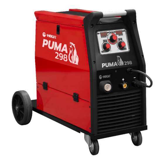
  • Seite 45: Kontroll Und Einstellfunktionen

    KONTROLL UND EINSTELLFUNKTIONEN Bild 1 Angetriebene Einheit grüne LED; wenn sie leuchtet, bedeutet dies, dass der Generator ordnungsgemäß mit Strom versorgt wird und betriebsbereit ist; das Blinken bedeutet, dass der Generator aufgrund ei- nes Alarms oder einer Änderung des Schweißverfahrens vorübergehend nicht verwendet werden kann. Thermische Alarm-LED;...
  • Seite 46: E-Hand Schweissen (Mma)

    • Im MIG/ MAG Synergic, zeigt das Display die vorgewählte Materialstärke in MM. Rechtes Display (5): während des Schweißens wird die aktuelle Schweißsspannung angezeigt. Bei nicht einschaltetem Schweißstrom (Leerlauf) zeigt die Anzeige den vorgewählten Parameter, einzu- stellen am rechten Knopf (7): •...
  • Seite 47: Berührungszünden Des Wig-Lichtbogen

    Schließen Sie das Ventil im Brenner-Handgriff. Öffnen Sie das Ventil am Druckminderer, danach • öffnen Sie das Ventil im Brenner-Handgriff und überprüfen die Gasmenge. BERÜHRUNGSZÜNDEN DES WIG-LICHTBOGEN • Fixieren Sie die Elektrode so das diese ca. 4-5mm aus der Gasdüse heraus ragt. •...
  • Seite 48: Austauschen Der Drahtführungsseele

    Hinweis: Beim einfädeln des Drahtes den Brennerhals von ihnen und anderen Per- sonen weg auf den Boden richten. Es besteht Verletzungsgefahr wenn der Draht aus dem Brennerhals tritt (Auge, Gesicht). Greifen Sie nicht mit den Fingern bei Einfädel- betrieb in den Drahtvorschub (Quetschgefahr). AUSTAUSCHEN DER DRAHTFÜHRUNGSSEELE.
  • Seite 49: Mig Manual Schweissen (Siehe Bild 1)

    MIG MANUAL SCHWEISSEN (SIEHE BILD 1) Bevor Sie das Schweißgerät einschalten vergewissern Sie sich, dass alle Komponenten richtig angeschlossen sind (Brennerschlauchpalet, Massekabel, u.s.w.). • Wählen Sie am Wahlschalter (6), der Frontsteuerung “Manual” an. • Schalten Sie den Hauptschalter (14), an der Rückseite des Schweißgerätes, ein. •...
  • Seite 50: Schutzgas Arten

    SCHUTZGAS ARTEN MATERAL EIGENSCHAFTEN Stahl Argon + CO2 Argon vermeidet Spritzer Argon + CO2 + O2 CO2 für tiefen Einbrand Aluminium Argon stabiler Lichtbogen, geringe Spritzer und gute Schmelzeigenschaften. Argon + Helium Höhere Wärmeeinbringung für dickere Wandstärken. Geringeres Porenrisiko. Edelstahl Argon + CO2 + O2 Stabiler Lichtbogen.
  • Seite 51 Drahtvorschubmotor arbeitet, Fehlerhafte Drahtvorschubmotor Drahtvorschubmotor austauschen. Draht wird nicht gefördert. (selten) Ungenügender Anpressdruck Anpressdruck erhöhen bzw. austau- schen. Drahtende hat Grad. Draht Gradfrei abschneiden. Drahtführungsseele verstopft oder Drahtführungsseele durchblasen beschädigt. (reinigen) oder ersetzen. Schlechter Einbrand Schweißspannung oder Drahtge- Parameter anpassen. schwindigkeit zu gering.
  • Seite 52: Schweisswissen

    Schlechte Schweißqualität Verstopfte Gasdüse. Düse säubern oder .austauschen Abstand Brenner zum Werkstück Brenner im richtigen Abstand zu groß halten. Zu geringer Gasfluss Stellen Sie sicher das sich noch Gas in der Flasche befindet und der Druckminderer richtig einge- stellt ist. Achten Sie darauf das das Gas nicht weggeblasen wird.
  • Seite 53 SMALTIMENTO DI APPARECCHI DA ROTTAMARE DA PARTE DI PRIVATI NELL’UNIONE EUROPEA Questo simbolo che appare sul prodotto o sulla confezione indica che il prodotto non deve essere smaltito assieme agli altri rifiuti domesti- ci. Gli utenti devono provvedere allo smaltimento delle apparecchiature da rottamare portandole al luogo di raccolta indicato per il riciclag- gio delle apparecchiature elettriche ed elettroniche.
  • Seite 54 The equipment has been designed in order to comply with the Directive 2009/125/EC and the Regulation 2019/1784/EU. Efficiency and idle power consumption: PART NUMBER 99825016 PRODUCT NAME PUMA 298 EFFICIENCY WHEN MAX POWER CONSUMPTION 87,00% IDLE POWER CONSUMPTION 10W EQUIVALENT MODEL No equivalent model The value of efficiency and consumption in idle state have been measured by method and conditions defined in the product standard EN 60974-1:20XX.
  • Seite 56 77613023...

Inhaltsverzeichnis