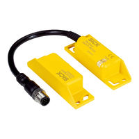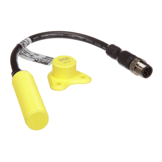
Sicherheitsschalter
Inhaltsverzeichnis
Function of this Document
57
Qualified Safety Personnel
59
Applications of the Safety Switches
60
General Safety Notes and Protective Measures
61
Environmental Protection
62
Fig. 1: Response Range
68
Fig. 2: Approach Directions
68
Fig. 3: Response Range on Rotation of the Actuator by 90
69
Fig. 4: Minimum Distance for Mounting Multiple Safety
70
Electrical Installation
71
Safety Notes for the Electrical Connection
71
M12 × 8 Sensor Connection Plug
74
Fig. 5: Pin Assignment M12 × 8 Sensor Connection Plug (TR4-S
74
M12 × 5 Sensor Connection Plug
75
Fig. 6: Pin Assignment Sensor Connection Plug M12 × 5 (TR4-S
75
Connection of a Single Safety Switch
76
Fig. 7: Connection of a Single TR4-S
76
Connection of Several Safety Switches in a Cascade
77
Fig. 9: Connection of Several TR4-S
79
Indication on Switching on
80
Teach-In (TR4 Unique Coded)
80
Teaching-In an Actuator
81
Teaching-In and Locking the TR4 Unique Coded
82
Error Displays of the TR4 Unique Coded During
83
In the Event of Faults or Errors
88
Error Displays of the Status/Diag LED
89
Fig. 13: Troubleshooting with Cascaded Safety Switches
90
Technical Specifications
91
Response Time of a Single Safety Switch TR4
91
Response Time for Multiple Cascaded TR4 Safety Switches
91
Fig. 14: Diagram of Magnetic Retaining Force (Only TR4-Sfxxxx)
95
Fig. 15: Area for the Measurement of the Magnetic Retaining
95
Dimensional Drawing TR4 Direct Sensor
96
Fig. 16: Dimensional Drawing TR4 Direct Sensor (MM)
96
Dimensional Drawing TR4 Direct Actuator
97
Fig. 17: Dimensional Drawing TR4 Direct Actuator (MM)
97
TR4-Sdxxxx Standard Transponder Safety Switches
98
TR4-Sexxxx Transponder Safety Switches with
98
Boundary Area Indication
98
Compliance with EU Directives
103
Direct Cylindrical
Inhaltsverzeichnis