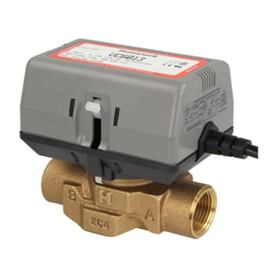
Inhaltszusammenfassung für Honeywell VC Series
- Seite 1 VC Series Installation instruction • Einbauanleitung 2-Way Zone Valves Keep instructions for later use! Anleitung zum späteren Gebrauch aufbewahren! 2-Wege Zonenventile...
- Seite 2 MU1H-2805GE25 R0107 www.honeywell.com...
-
Seite 3: Inhaltsverzeichnis
4. Installation ........5 5. Wiring ........... 6 6. Checkout and service ....7 1. Anwendungsbereich ....8 2. Spezifikationen ......8 3. Handöffner ........9 4. Einbau .......... 9 5. Verdrahtung ....... 10 6. Probebetrieb und Wartung ..11 MU1H-2805GE25 R0107 www.honeywell.com... -
Seite 4: Application
These 2-Way valves are designed for ON-OFF "Zone" a chronotherm or other suitable two-position controller. 2. Specifications The following specifications are nominal and conform to generally accepted industry standards. Honeywell is not responsible for damages resulting from misapplication or misuse of its product. Voltage 230V 50-60Hz, standard models. -
Seite 5: Manual Opener
Put the VC actuator manual lever (Fig. 6) in the manual open (middle) position to allow initial system flushing with the actuator mounted. This operation must be done without electrical hook-up MU1H-2805GE23 R0107 www.honeywell.com... -
Seite 6: Wiring
(for SPST Controller) (Brown & Black open) Pin # 3 & 6 open (valve closes) Blue & Brown energised Pin # 2 & 3 energised Stem down (Brown & Black closed) Pin # 3 & 6 closed (valve opens) MU1H-2805GE23 R0107 www.honeywell.com... -
Seite 7: Checkout And Service
(if present) should close and make at the end damaged, replace the entire actuator assembly of the opening stroke to activate auxiliary equip- Note: Honeywell hydronic valves are designed and ment. tested for silent operation in properly designed 3. Lower the set point of the zone thermostat below and installed systems. -
Seite 8: Anwendungsbereich
Hausheizungssystemen bzw. für die 2. Spezifikationen Folgende Spezifikationen sind Nennwerte und entsprechen allgemein gültigen Industriestandards. Honeywell haftet nicht für Schäden, die durch falsche Verwendung oder Zweckentfremdung seiner Produkte entstehen. Spannung 230V 50-60Hz, Standardmodelle. Modelle mit 24V 50Hz sind auf Anfrage erhältlich... -
Seite 9: Handöffner
4. Führen Sie nach Abschluss des Einbaus immer eine unter (2) beschriebene Vorgehensweise umgekehrt gründliche Überprüfung durch. wird. 5. Unterbrechen Sie die Stromversorgung, bevor Sie elektrische Leitungen verbinden, um einen elektri- schen Schlag und Beschädigungen des Systems zu vermeiden. MU1H-2805GE23 R0107 www.honeywell.com... -
Seite 10: Verdrahtung
COM (SPST- (Braun und Schwarz offen) Pin 3 und 6 offen (Ventil schließt) Regler) Blau und Braun unter Spannung Pin 2 und 3 unter Spannung Schaft unten (Braun und Schwarz geschlossen) Pin 3 und 6 geschlossen (Ventil öffnet) MU1H-2805GE23 R0107 www.honeywell.com... -
Seite 11: Anschluss
Stell- gangs schließen, um die Hilfseinrichtungen zu akti- glied ausgetauscht werden. vieren. Hinweis: Heizungsventile von Honeywell sind so konzi- 3. Stellen Sie den Sollwert des Zonenthermostats auf piert und getestet worden, dass in fachgerecht einen Wert unterhalb der Raumtemperatur. - Seite 12 Phone: (401) 7 38-42 90 www.honeywell.se Fax: (401) 7 38-41 56 Manufactured for and on behalf of the Environmental and Combustion Controls Division of Honeywell Tech- nologies Sàrl, Ecublens, Route du Bois 37, Switzer- land or by its Authorized Representative. MU1H-2805GE25 R0107 January 2007 ©...


