Herunterladen Inhalt Inhalt Diese Seite drucken
Vorschau ausblenden Andere Handbücher für 2000mm Beaver V2:

Werbung

Verfügbare Sprachen

Verfügbare Sprachen

2000mm Beaver V2
Instruction Manual
Bedienungsanleitung
Manuel d'utilisation
SIMPLE
FLOATS
RIGID
FMSMODEL.COM
Simple assembly
Optional floats
Strong durable EPO

Werbung

Inhaltsverzeichnis
loading

Inhaltszusammenfassung für FMS 2000mm Beaver V2

  • Seite 1 2000mm Beaver V2 Instruction Manual Bedienungsanleitung Manuel d’utilisation SIMPLE FLOATS RIGID FMSMODEL.COM Simple assembly Optional floats Strong durable EPO...
  • Seite 2 WARNING WARNING: Read the ENTIRE instruction manual to become familiar with the features of the product before operating. Failure to operate the product correctly can result in damage to the product,personal property and cause serious injury. This is a sophisticated hobby product and NOT a toy. It must be operated with caution and common sense and failure to do so could result in injury or damage to the product or other property.
  • Seite 3: Inhaltsverzeichnis

    FMS 2000mm Beaver V2 Official release notes! • Hollowed wing design reduces flying weight The FMS 2000mm Beaver V2 is a real “pilot’s plane”. Weighing • Metal landing gear withstands the hardest of landings in at just 3800g and having over 5000g of thrust- the Beaver V2 •...
  • Seite 4: Model Assembly

    Model assembly Landing gear set installation 1.Attach the landing gear set to the landing gear slot on the underside of the fuselage. The five screws are installed as shown . Main wing installation 1.Slide the wing spar into the fuselage then install both wings over the wing spar and into the fuselage pass-through of the fuselage.
  • Seite 5 Model assembly 2.Install the 2 wing struts on the fuselage mount using 2 R-clips. HKM3.0*26mm 3. Secure the wing structure onto the fuselage using 4 screws as shown. Ensure that these screws are securely tightened. Horizontal stabilizer installation 1. Slide the horizontal stabilizer spar into the pass through at the rear of the aircraft.
  • Seite 6 Model assembly 3. Install the 4 included screws to secure the stabilizer halves. Vertical stabilizer installation 1. Connect the rudder and elevator servo connectors to the servo extensions in the fuselage. 2. Slide the vertical tail assembly into slot in the fuselage. CAUTION:DO NOT crush or damage the wiring when attaching the vertical tail assembly to the fuselage.
  • Seite 7 Model assembly Installation of the vortex generators 1. Carefully apply CA to the indentations located on the leading edge of the wings. 2. Carefully slide the vortex generators onto the indentations as shown. Installation of other scale components 1. Carefully adhere the pitot tube to the leading edge of the wing as shown.
  • Seite 8 Model assembly 4.Adhere the antenna to the top of the center wing box. Optional glider release hitch installation 1. Install the glider release mechanism to the top of the fuselage and secure with 4 screws as shown. KA2.6x12mm...
  • Seite 9 Model assembly 2. Install the aerodynamic fairing for the mechanism to the top of the fuselage and secure with two screws. Linkage rod installation 1.With the servo centered, install and adjust the pushrod and clevises. Connect the clevis to the outermost hole on the control horn.
  • Seite 10 Model assembly Optional float installation 1. Install the struts to both sides of the float. The front strut is longer with 422mm length, the rear strut is shorter with 412mm length. Wrong installation will cause difficulty landing and taking off. 2.Install the float strut to the float with 8 screws as picture shows.
  • Seite 11: Propeller Installation

    Model assembly 3.With the fuselage bottom facing up, carefully install the float set to the fuselage with 6 screws. 4.Connect the float servo and fuselage connector. Note: black wire to mark "-", yellow wire to mark "s" Propeller installation 1.Assemble the spinner and propeller as shown. Note: the motor should rotate clockwise when viewing the plane from the rear.
  • Seite 12: Battery Installation

    Battery installation 1. Pull back on the release tab and remove the battery hatch. 2. Apply hook tape to the cable end of the battery. 3. Make sure the battery is secured using hook tape. Note: batteries from different manufacturers will vary in weight and size, it is therefore important to check the center of gravity of the aircraft before every flight.
  • Seite 13: Control Throws

    Transmitter and model setup Before getting started, bind your receiver with your transmitter. Bank left Please refer to your transmitter manual for proper operation. CAUTION: To prevent personal injury, DO NOT install the propel- ler assembly onto the motor shaft while testing the control surfac- es.
  • Seite 14: Clevis Installation

    Clevis installation 1.Pull the tube from the clevis to the linkage. 2.Carefully spread the clevis, then insert the clevis pin into the desired hole in the control horn. 3.Move the tube to hold the clevis on the control horn. Control horn and servo arm settings More control throw Horns Arms...
  • Seite 15: Before Flying The Model

    Before flying the model Flying course Find a suitable flying site Take off While applying power, slowly steer to keep the model straight. Find a flying site clear of buildings, trees, power lines and other obstructions. Until you know how much area will be The model should accelerate quickly.
  • Seite 16: Troubleshooting

    Trouble shooting Problem Possible Cause Solution Aircraft will not respond to -Lower throttle stick and throttle trim to lowest settings. -ESC is not armed. the throttlebut responds to -Reverse throttle channel on transmitter. -Throttle channel is reversed. other controls. -Damaged spinner, propeller, -Replace damaged parts.
  • Seite 17: Warnhinweise

    Warnhinweise WARNUNG: Lesen Sie die GESAMTE Bedienungsanleitung, um sich vor der Inbetriebnahme mit den Funktionen des Produkts vertraut zu machen. Wenn das Produkt nicht ordnungsgemäß bedient wird, kann dies zu Schäden am Produkt oder persönlichem Eigentum führen und schwere Verletzungen verursachen.Dieses Produkt ist kein Spielzeug! Es muss mit Vorsicht und gesundem Menschenver- stand betrieben werden.
  • Seite 18: Einleitung

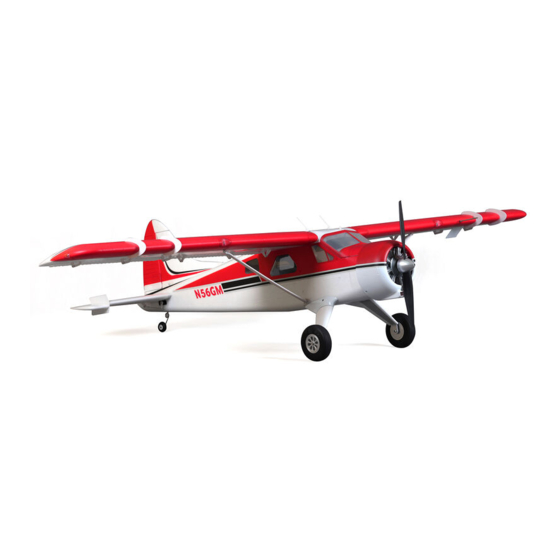
    Dank des Schnellverschlusssystems an Flügeln und Rumpf • Optionale Schwimmer kann die Beaver trotz seiner großen Spannweite problemlos Inhalt transportiert werden. Die FMS 2000mm Beaver V2 baut auf den Erfolg des Einleitung ············································································· 18 Vorgängers auf und bietet einige Neuerungen: Lieferumfang ········································································...
  • Seite 19: Montage Des Modells

    Montage des Modells Montage des Fahrwerks 1. Montieren Sie das Fahrwerk mit den 5 entsprechenden Schrauben an der Unterseite des Rumpfes. Montage der Tragflächen 1. Schieben Sie das Flächenrohr in den Rumpf und montieren Sie beide Flächen. HINWEIS : Achten Sie auf den Sitz der Konnektoren zwischen Fläche und Rumpf.
  • Seite 20: Montage Des Höhenleitwerks

    Montage des Modells 2. Montieren Sie die Flächenstreben mit den beiden R-Clips. HKM3.0*26mm 3. Sichern Sie die Flächen indem Sie die 4 Schrauben wie abgebildet von oben in den Rumpf schrauben. Achten Sie auf einen festen Halt. Montage des Höhenleitwerks 1.
  • Seite 21 Monatge des Modells 3. Montieren Sie das Höhenleitwerk mit den 4 Schrauben. Montage des Seitenleitwerks 1. Verbinden Sie zuerst die Servokabel für das Seitenruder miteinander. 2. Schieben Sie das Seitenleitwerk in den Rumpf. ACHTUNG: Achten Sie darauf die Kabel nicht einzuklemmen. 3.
  • Seite 22: Montage Der Vortex Generatoren

    Montage des Modells Montage der Vortex Generatoren 1. Geben Sie etwas Sekundenkleber auf die Fläche. 2. Kleben Sie die Vortex Generatoren auf. Montage der Scale-Details 1. Verkleben Sie die Kleinteile wie abgebildet mit Sekundenkleber. 2. Verkleben Sie die Kleinteile wie abgebildet mit Sekundenkleber.
  • Seite 23: Montage Der Optionalen Schleppkupplung

    Montage des Modells 3. Befestigen Sie die Antennen wie abgebildet. Montage der optionalen Schleppkupplung 1. Befestigen Sie die Schleppkupplung mit 4 Schrauben an der Oberseite des Rumpfes. KA2.6x12mm...
  • Seite 24: Montage Der Anlenkungen

    Monatge des Modells 2. Montieren Sie den Mechanismus an der Oberseite mit zwei Schrauben. Montage der Anlenkungen 1. Montieren Sie die Anlenkungsgestänge an am Servo, welches sich dabei in neutraler Stellung befinden sollte.
  • Seite 25: Montage Der Optionalen Schwimmer

    Montage des Modells Montage der optionalen Schwimmer 1. Verbinden Sie das Schwimmerset wie abgebildet mit den Streben. 2. Befestigen Sie die Schwimmer mit Hilfer der 8 Schrauben am Gestell.
  • Seite 26: Montage Des Propellers

    Monatge des Modells 3. Drehen Sie das Flugzeug auf den Kopf um das komplette Schwimmerset mit den 6 Schrauben am Rumpf zu montie- ren. 4. Verbinden Sie das Schwimmruder-Servo mit dem Kabel im Rumpf Hinweis: Schwarzes Kabel "-", gelbes Kabel "+" Montage des Propellers 1.
  • Seite 27: Abschlussmontage

    Einstezen des Flugakkus 1. Nehmen Sie die Haube ab. 2. Befestigen Sie den Akku mit dem Klettband. 3. Schieben Sie den geladenen Akku mit den Kabeln nach hinten in bis ganz nach vorne im Akkufach. Hinweis: Der Schwerpunkt des Modells kann durch verschie- ben des Akkus verändert werden.
  • Seite 28: Testen Der Steuerfunktionen

    Testen der Steuerfunktionen Bevor Sie mit diesem Schritt beginnen, binden Sie bitte der Rollen links Anleitung ihres Senders entsprechend den Empfänger mit dem Sender. ACHTUNG: Um mögliche Verletzungen zu vermeiden darf der Propeller bei dem Testen der Ruder NICHT auf der Welle montiert sein.
  • Seite 29: Montage Der Gabelköpfe

    Montage der Gabelköpfe 1. Ziehen Sie den Ring vom Gabelkopf zum Gestänge. 2. Spreizen Sie den Gabelkopf vorsichtig und führen Sie den Gabelkopfstift in das gewünschte Loch im Ruderhorn ein. 3. Befestigen Sie den Ring um den Gabelkopf am Ruderhorn zu halten.
  • Seite 30: Vor Dem Erstflug

    Vor dem Erstflug Fluggrundlagen Finden Sie einen geeigneten Flugplatz Starten Finden Sie einen Flugplatz frei von Gebäuden, Bäumen, Beschleunigen Sie das Modell vorsichtig und steuern Sie es langsam um es gerade zu halten. Erhöhen Sie die Stromleitungen und anderen Hindernissen. Bis Sie wissen, Beschleunigung und halten Sie eine gleichmäßige wie viel Fläche Sie zum fliegen brauchen, wählen Geschwindigkeit um das Modell in einem schönen Anstellwinkel...
  • Seite 31: Mögliche Ursache

    Problemlösungen Problem Mögliche Ursache Lösung Modell nimmt kein Gas an, -Gasknüppel ist nicht ganz unten oder Trimmung zu hoch -Regler reagiert nicht andere Steuerungsbefehle -Gaskanal am Sender umkehren -Gaskanal ist umgekehrt funktionieren aber -Spinner, Propeller,Motor oder -Defekte Teile austauschen Ungewöhnliche Motorhalterung defekt -Lose Teile befestigen Propellergeräusche oder...

Inhaltsverzeichnis