Inhaltsverzeichnis
Werbung
Quicklinks
Werbung
Inhaltsverzeichnis

Verwandte Anleitungen für HEIDENHAIN VM 182


Inhaltszusammenfassung für HEIDENHAIN VM 182
- Seite 1 Betriebsanleitung Operating Instructions VM 182 10/2015...
-
Seite 3: Inhaltsverzeichnis
18 Abbau Abtastkopf und Maßstab 18 Dismounting the scanning head and scale Weitere Informationen siehe HEIDENHAIN Prospekt: Messgeräte zur Abnahme und Kontrolle von Werkzeugmaschinen For more information, refer to the HEIDENHAIN brochure Measuring Systems for Machine Tool Inspection and Acceptance Testing... -
Seite 4: Warnhinweise
Warnhinweise Warnings Achtung: Die Montage und Inbetriebnahme ist von einer Fachkraft für Elektrik und Feinmechanik unter Beachtung der örtlichen Sicherheitsvorschriften vorzunehmen. Note: Mounting and commissioning is to be conducted by a specialist in electricity and precision mechanics under compliance with local safety regulations. Maße in mm Dimensions in mm... - Seite 5 Treat the inspection tool with care and do not expose it to shock or vibration. Um eine fehlerfreie Prüfung durchzuführen, empfehlen wir, das Prüfwerkzeug regelmäßig durch den HEIDENHAIN-Service überprüfen zu lassen. For an error-free inspection performance we recommend having the inspection tool checked regularly by HEIDENHAIN Service.
-
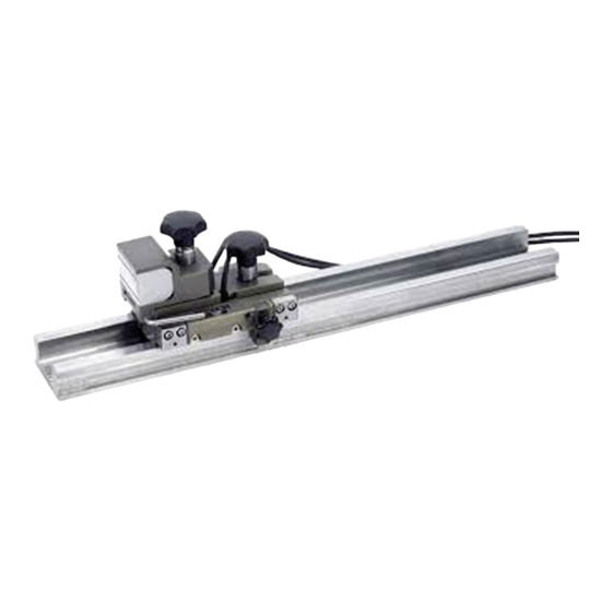
Seite 6: Lieferumfang
Lieferumfang Items Supplied Maßstab VM 182 Hilfswagen mit Abtastkopf VM 182 scale auf Führungsschiene Auxiliary carriage with scanning head on guide rail EIB 741 PC-Software ACCOM... -
Seite 7: Messaufbau Mit Eib 741 Und Accom - Software
Messaufbau mit EIB 741 und ACCOM - Software Measuring setup with EIB 741 and ACCOM software NC-Programm Testprogramm Notebook ACCOM Testprogramm EIB 741... -
Seite 8: Allgemeine Hinweise Zum Anbau
Allgemeine Hinweise zum Anbau General notes on mounting Achtung: Bei der Montage muss der Hilfswagen so auf dem Maßstab angebracht sein, dass sich die Klemmschraube S und der Andruckhebel auf der selben Seite befinden wie das Typenschild. Note: During mounting, the auxiliary carriage must be placed on the scale so that the clamping screw S and the ejector lever are on the same side as the ID label. - Seite 9 Anbaufläche mit sauberem, fusselfreiem Tuch und destilliertem Spiritus oder Isopropylalkohol reinigen. Clean the mounting surface with a clean lint-free cloth and distilled spirit or isopropyl alcohol. Üblicherweise wird die Montage über gebräuchliche Werkstückspannelemente auf den Arbeitstisch der Werkzeugmaschine erfolgen. The scale is normally mounted to the machine tool’s worktable with common workpiece clamping elements.
-
Seite 10: Anbau Maßstabsprofil
Anbau Maßstabsprofil Mounting the scale housing 0,05 Die Auflagefläche für den Maßstab muss innerhalb 0,1 mm parallel zur Maschinenführung und innerhalb 0,05 mm eben sein. The bearing surface of the scale must be parallel within 0.1 mm to the machine guideway and flat to within 0.05 mm. Messuhr am Spindelkasten befestigen und zur Messachse ausrichten. -
Seite 11: Anbau Abtastkopf
Anbau Abtastkopf Mounting the scanning head Für den Abtastkopf muss im Regelfall ein einfaches Adapterstück mit einer geeigneten Ankoppelfläche für den Kupplungsmagneten angefertigt werden. Der Trägerkörper muss aus ferromagnetischem Stahl sein, damit der Kupplungsmagnet des Abtastkopfes haften kann. In most cases, a simple adapter must be fabricated for the scanning head with a suitable surface for the coupling magnets. - Seite 12 Elektrischen Anschluss gemäß Messaufbau mit EIB 741 herstellen. Siehe dazu Seite 7 . Make the electrical connection according to the measuring setup with the EIB 741. See page 7 . Die Führungsschiene mit Hilfswagen und Abtastkopf auf den Maßstab aufstecken. Insert the guide rail with auxiliary carriage and scanning head onto the scale.
- Seite 13 Schraube S lösen und Hilfswagen in den Maßstab einschieben. Signale überprüfen 0,6 V bis 1 V Loosen the screw S and slide the auxiliary carriage into the scale. Check the signals for 0.6 V to 1 V Abdrückhebel H soweit nach vorne drücken, bis die Andrückwalze W vorne heraus steht.
- Seite 14 Die Klemmschraube S am Kupplungsmagneten K lösen, so dass sich der Kupplungsmagnet lockert. Den Hilfswagen an das Adapterstück der Maschinenpinole schieben. Das Adapterstück liegt nun an der vorstehenden Walze W des Kupplungsmagneten an. Loosen the clamping screw S on the coupling magnet K so that the coupling magnet loosens.
- Seite 15 Alle drei Auflagepunkte P des Kupplungsmagneten müssen an der Ankoppelfläche anliegen. All three points P of the coupling magnet must contact the coupling surface. Die Klemmschraube S am Kupplungsmagneten wieder fest ziehen. Signale überprüfen 0,6 V bis 1 V Retighten the clamping screw S on the coupling magnet.
- Seite 16 Die Anpasselektronik so anbringen, dass die beiden Anschlusskabel keine Kräfte auf den Abtastkopf ausüben können. Die beiden Anschlusskabel müssen auf dem gesamten Verfahrweg frei beweglich sein. Connect the interface electronics so that both cables exercise no force on the scanning head. Both connecting cables must move freely over the entire path of traverse.
- Seite 17 Hilfswagen aus dem Maßstab herausziehen, bzw. bei kurzer Mess- strecke nur aus der Messzone schieben. Signale überprüfen 0,6 V bis 1 V Ist das Signal kleiner 0,6 V muss der Anbau des Abtastkopfes wiederholt werden. Slide the auxiliary carriage out of the scale or, for short measuring lengths, only out of the measuring zone.
-
Seite 18: Abbau Abtastkopf Und Maßstab
Abbau Abtastkopf und Maßstab Dismounting the scanning head and scale Nach der Vergleichsmessung den Hilfswagen in den Abtastkopf einschieben. After the comparative measurement, slide the auxiliary carriage into the scanning head. Klemmschraube S für den Abtastkopf festziehen. Tighten the clamping screw S for the scanning head. - Seite 19 Den Abdrückhebel H nach vorne drücken, so dass das Adapterstück mit Hilfe der Walze vom Kupplungsmagneten abdocken kann. Press the ejector lever H forward so that, with the aid of the roller, the adapter can be undocked. Hilfswagen auf die Führungsschiene herausschieben und mit Klemmschraube S fixieren.
- Seite 20 DR. JOHANNES HEIDENHAIN GmbH Dr.-Johannes-Heidenhain-Straße 5 83301 Traunreut, Germany { +49 8669 31-0 | +49 8669 32-5061 E-mail: info@heidenhain.de Technical support | +49 8669 32-1000 Measuring systems { +49 8669 31-3104 E-mail: service.ms-support@heidenhain.de TNC support { +49 8669 31-3101 E-mail: service.nc-support@heidenhain.de...