Herunterladen Inhalt Inhalt Diese Seite drucken
Inhaltsverzeichnis

Werbung

Verfügbare Sprachen
  • DE

Verfügbare Sprachen

  • DEUTSCH, seite 32
USER´S MANUAL
BEDIENUNGSANLEITUNG
MANUEL D´UTILISATION
MANUAL DE USUARIO
INSTRUKCJA OBSŁUGI
MANUALE D´USO
H1 D / H1 T
COMPACT HOUSE LIGHT - DAYLIGHT / TUNGSTEN
CLH1D(WH) / CLH1T(WH)

Werbung

Inhaltsverzeichnis
loading

Inhaltszusammenfassung für Cameo H1 D

  • Seite 1 USER´S MANUAL BEDIENUNGSANLEITUNG MANUEL D´UTILISATION MANUAL DE USUARIO INSTRUKCJA OBSŁUGI MANUALE D´USO H1 D / H1 T COMPACT HOUSE LIGHT - DAYLIGHT / TUNGSTEN CLH1D(WH) / CLH1T(WH)
  • Seite 2: Inhaltsverzeichnis

    CONTENTS / INHALTSVERZEICHNIS / CONTENU / CONTENIDO / TREŚĆ / CONTENUTO ENGLISH INFORMATION ON THIS USER MANUAL INTENDED USE DEFINITIONS AND SYMBOL DECLARATIONS SAFETY INSTRUCTIONS INSTRUCTIONS FOR INDOOR INSTALLATION EQUIPMENT INCLUDED INTRODUCTION CONNECTIONS, OPERATING AND DISPLAY ELEMENTS CABLING THE CONNECTION TERMINAL CONTROL VIA THE UNICON REMOTE UNIT DIFFUSERS TRUSS INSTALLATION...
  • Seite 3 CONTENTS / INHALTSVERZEICHNIS / CONTENU / CONTENIDO / TREŚĆ / CONTENUTO FRANÇAIS INFORMATIONS CONCERNANT CE MANUEL D’UTILISATION UTILISATION CONFORME EXPLICATIONS DES TERMES ET DES SYMBOLES CONSIGNES DE SÉCURITÉ CONSIGNES POUR LES APPAREILS D’INSTALLATION INTÉRIEURE CONTENU DE LA LIVRAISON PRÉSENTATION RACCORDEMENTS, ÉLÉMENTS DE COMMANDE ET D’AFFICHAGE CÂBLAGE DE LA BORNE DE RACCORDEMENT COMMANDE PAR UNITÉ...
  • Seite 4 CONTENTS / INHALTSVERZEICHNIS / CONTENU / CONTENIDO / TREŚĆ / CONTENUTO POLSKI INFORMACJE DOTYCZĄCE NINIEJSZEJ INSTRUKCJI OBSŁUGI UŻYTKOWANIE ZGODNE Z PRZEZNACZENIEM OBJAŚNIENIA TERMINÓW I SYMBOLI ZASADY BEZPIECZEŃSTWA UWAGI DOTYCZĄCE URZĄDZEŃ SŁUŻĄCYCH DO MONTAŻU WE WNĘTRZACH ZAKRES DOSTAWY WPROWADZENIE PRZYŁĄCZA, ELEMENTY OBSŁUGI I WSKAŹNIKI OKABLOWANIE LISTWY PRZYŁĄCZENIOWEJ OBSŁUGA ZA POMOCĄ...
  • Seite 5: English

    This device has been developed and manufactured to the highest quality standards to ensure many years of problem-free operation. Please read this user manual carefully to be able to use your new Cameo product quickly and optimally. Further information about Cameo Light is avail- able on our website CAMEOLIGHT.COM.
  • Seite 6: Safety Instructions

    This symbol identifies hazards that can cause electric shock. This symbol identifies hazardous areas or hazardous situations. This symbol indicates hazards caused by hot surfaces. This symbol indicates hazards caused by intense light sources. This symbol indicates a device in which there are no user-replaceable parts. This symbol indicates additional information on the operation of the product.
  • Seite 7 CAUTION: 1. Do not switch on the device if it has been exposed to extreme temperature fluctu- ations (for example, following transport). Moisture and condensation can damage the device. Switch on the device only when it has reached room temperature. 2.
  • Seite 8 CAUTION: 1. Moving components such as mounting brackets may become jammed. 2. In the case of devices with motor-driven components, there is a risk of injury due to the movement of the device. Sudden movement of the device can cause shock reactions.
  • Seite 9 4. A permanently installed lamp is installed in this lighting unit which must not be replaced by the user. In the event of a fault, please contact your distribution partner. SIGNAL TRANSMISSION BY RADIO (e.g. W-DMX or audio radio systems): The quality and performance of wireless signal transmissions generally depends on the ambient conditions.
  • Seite 10: Instructions For Indoor Installation Equipment

    TRANSMISSION VIA W-DMX WARNING: In general, wireless DMX transmission must not be used for applica- tions involving safety-related factors that might result in personal injury or property damage in the event of a failure. This applies in particular to moving scene or traverse structures, DMX-controlled motors/lifts or lifting devices for operating DMX-operated platform lifts, hydraulic systems or comparable moving components.
  • Seite 11: Introduction

    INTRODUCTION DAYLIGHT PENDANT SPOTLIGHT WITH W-DMX™ CLH1D (black housing) CLH1DWH (white housing) TUNGSTEN (WARM WHITE) PENDANT SPOTLIGHT WITH W-DMX™ CLH1T (black housing) CLH1TWH (white housing) CONTROL FUNCTIONS • 1-channel, 2-channel and 4-channel DMX control • W-DMX™ • Master/slave modes • Standalone functions FEATURES •...
  • Seite 12: Connections, Operating And Display Elements

    CONNECTIONS, OPERATING AND DISPLAY ELEMENTS CONNECTION TERMINAL The connection terminal is used for voltage and signal supply for fixed installations. Observe the safety instructions for wiring the terminal under CABLING THE TERMINAL. FUSE Fuse holder for 5 x 20 mm fuses. CAUTION: Replace the fuse only with a fuse of the same type and value.
  • Seite 13: Dip Switch Function

    DIP SWITCH Eight DIP switches for basic configuration of the spotlight. To fully configure the spotlight, you need the optionally available UNICON remote unit. DIP switch Function Explanation 1 ON Selection of RJ45 wire pair The incoming DMX signal can be routed to one of the 4 available wire pairs 2 ON 3 ON...
  • Seite 14: Status-Led

    STATUS LED The LED shows the current status of the spotlight when controlled via cable and W-DMX. Control via cable (DMX, RJ45) Control via W-DMX™ LED lights up DMX signal is LED flashes Activate W-DMX Permanently blue present Red with approx. 1 Hz LED flashes red no DMX signal...
  • Seite 15: Cabling The Connection Terminal

    CABLING THE CONNECTION TERMINAL HAZARD: Opening the spotlight and connecting cables to the terminal connector requires specialist knowledge and may only be carried out by specially trained person- nel! If you are not suitably qualified, do not attempt to open the spotlight and attach cable yourself.
  • Seite 16: Control Via The Unicon Remote Unit

    CONTROL VIA THE UNICON REMOTE UNIT Operation of the spotlight models H1 D and H1 T is identical. For simplicity, the model designation H1 D is used in the following text and in the illustrations.
  • Seite 17  in the display. A list of all connected RDM devices is then displayed (in the example H1 D/H1 D and H1 FC/H1 FC; the first part of the displayed RDM device shows the device model, the second part after "/" is an additional designation that can be adapted in the Label menu item for easier identification).
  • Seite 18 Number of channels in current DMX mode Sensor LED temperature (press  to display) Fixture Menu Individual Cameo device menu for editing settings (see DEVICE MENU [Fixture Menu]) Label In the RDM/Fixture menu, select Label and confirm the selection to individually name the RDM device.
  • Seite 19 DEVICE MENU (Fixture Menu): Select the desired menu item with  or , or by turning the encoder, confirm with  or by pressing the encoder. Back with  or BACK. Set the value or status with  or , or by turning the encoder, confirm with  or by pressing the encoder.
  • Seite 20: Timer Function

    STATIC STANDALONE MODE The standalone mode Static allows the Dimmer, Dimmer Fine and Strobe values to be set directly on the device with values between 000 and 255, in a similar way to with a DMX controller. In this way, an individual scene can be created without an additional DMX controller. Select Stand Alone, confirm the selection, then select Static and confirm again.
  • Seite 21 SYSTEM SETTINGS (Settings) Select Settings and confirm. This will take you to the submenu for configuring the submenu items (see table): Settings DMX Fail = Operational status Hold last command is retained with DMX signal fault Blackout Activates blackout Full On 100% output Dimmer = Dimmer curve...
  • Seite 22 Power = Operating mode Constant Constant brightness over long periods Maximum Maximum brightness Factory = Reset to factory Reset? Reset to factory settings: Reset settings Perform reset:  or press encoder Cancel:  or press BACK SYSTEM INFORMATION (SysInformation) Select SysInformation and confirm. This will take you to the submenu for accessing the system information (see table): SysInformation Firmware...
  • Seite 23: Diffusers

    DIFFUSERS The spotlight is supplied with 3 diffusers (1x pre-assembled), which have different dispersion characteristics (20° [narrow], 35° [middle], 45° [wide]). The beam angle of the spotlight can therefore be individually adjusted to 20°, 35°, or 45°. Loosen the four screws (A) on the retaining ring on the front of the spotlight with a suitable tool and remove the retaining ring from the spotlight.
  • Seite 24: Truss Installation

    TRUSS INSTALLATION HAZARD: Overhead mounting requires extensive experience, including the calculation of the load limit values of the installation material and regular safety inspection of all installation materials and spotlights. If you do not have these qualifications, do not attempt to perform an installation yourself. Refer instead to a qualified professional. There is a risk that devices that are incorrectly mounted and secured may come loose and fall down.
  • Seite 25 For suspended installation, the mounting bracket can be completely removed from the spotlight to create a consistent and discreet appearance. To do this, loosen and both knob screws (A) from the mounting bracket and remove it. Remove the sockets (B) on each side of the spotlight with a suitable tool. Cover the mounting holes (C) with the sliding metal strips in the grooves (D).
  • Seite 26: Care, Maintenance And Repair

    CARE, MAINTENANCE AND REPAIR In order to ensure the long-term, proper functioning of the device, it must be regularly cleaned and, if necessary, maintained. The maintenance requirement depends on the intensity of use and the environment in which it is used. We generally recommend a visual inspection before each operation.
  • Seite 27: Optional Accessories

    PLEASE NOTE! For conversion or retrofit sets provided by the manufacturer, it is essential to observe the installation instructions included. OPTIONAL ACCESSORIES CLIREMOTE RDM-based remote unit UNICON with touch colour display, DMX and RJ45 connection CLH1CKB (BLACK) CLH1CKW (WHITE) Ceiling installation kit for H1 spotlights CLH1HALFSNOOT (BLACK) CLH1HALFSNOOTWH (WHITE) "Half Snoot"...
  • Seite 28 CLH1SNOOT (BLACK) CLH1SNOOTWH (WHITE) "Snoot" protection for H1 spotlights CLH1WALLMOUNT (BLACK) CLH1WALLMOUNTWH (WHITE) Wall mount for H1 spotlights...
  • Seite 29: Technical Data

    TECHNICAL DATA Product number: CLH1D (WH) CLH1T (WH) Product type: LED spotlight LED spotlight Type: Installation spotlight Installation spotlight Colour spectrum: Daylight 6500 K Warm white 3000 K Number of LEDs: LED type: 80 W COB 80 W COB LED PWM frequency: 800 Hz, 1200 Hz, 2000 Hz, 800 Hz, 1200 Hz, 2000 Hz, 3600 Hz, 12 kHz, 2 kHz...
  • Seite 30: Minimum Distance To Illuminated Surface

    Dimensions 128 x 255 mm 128 x 255 mm (Ø x L, without mounting bracket): Weight 2.8 kg 2.8 kg (incl. mounting bracket): Scope of delivery (includ- Mounting bracket (pre-assem- Mounting bracket (pre-assem- ed): bled) bled) 3x diffuser (1x pre-assembled) 3x diffuser (1x pre-assembled) Accessories (optional): Ceiling installation kit...
  • Seite 31: Manufacturer's Declarations

    MANUFACTURER’S DECLARATIONS MANUFACTURER’S WARRANTY & LIMITATION OF LIABILITY Adam Hall GmbH, Adam-Hall-Str. 1, D-61267 Neu Anspach / E-mail Info@adamhall.com / +49 (0)6081 / 9419-0. Our current warranty conditions and limitation of liability can be found at: https://cdn-shop.adamhall.com/media/pdf/Manufacturers-Declarations-CAMEO_DE_EN_ES_ FR.pdf. Contact your sales partner for service. UKCA- CONFORMITY Hereby, Adam Hall Ltd.
  • Seite 32: Deutsch

    Dieses Gerät wurde unter hohen Qualitätsanforderungen entwickelt und gefertigt, um viele Jahre einen reibungslosen Betrieb zu gewährleisten. Bitte lesen Sie diese Bedienungsanleitung sorgfäl- tig, damit Sie Ihr neues Produkt von Cameo Light schnell und optimal einsetzen können. Weitere Informationen über Cameo Light erhalten Sie auf unserer Website CAMEOLIGHT.COM.
  • Seite 33: Sicherheitshinweise

    Dieses Symbol kennzeichnet Gefahren, die einen elektrischen Schlag verursachen können. Dieses Symbol kennzeichnet Gefahrenstellen oder gefährliche Situationen. Dieses Symbol kennzeichnet Gefahren durch heiße Oberflächen. Dieses Symbol kennzeichnet Gefahren durch intensive Lichtquellen. Dieses Symbol kennzeichnet ein Gerät, in dem sich keine vom Benutzer austausch- baren Teile befinden.
  • Seite 34 WARNUNG: 1. Das Gerät darf nicht in Betrieb genommen werden, wenn es offensichtliche Beschädigungen aufweist. 2. Das Gerät darf nur im spannungsfreien Zustand installiert werden. 3. Wenn das Netzkabel des Geräts beschädigt ist, darf das Gerät nicht in Betrieb genommen werden. 4.
  • Seite 35 WARNUNG: 1. Verwenden Sie das Gerät nur in der vorgesehenen Art und Weise. 2. Betreiben Sie das Gerät nur mit dem vom Hersteller empfohlenen und vorgesehe- nen Zubehör. 3. Beachten Sie bei der Installation die für Ihr Land geltenden Sicherheitsvorschrif- ten.
  • Seite 36 ACHTUNG: 1. Installieren und betreiben Sie das Gerät nicht in der Nähe von Heizkörpern, Wärme speichern, Öfen oder sonstigen Wärmequellen. Sorgen Sie dafür, dass das Gerät immer so installiert ist, dass es ausreichend gekühlt wird und nicht überhitzen kann. 2. Platzieren Sie keine Zündquellen wie z.B. brennende Kerzen in der Nähe des Geräts.
  • Seite 37 SIGNALÜBERTRAGUNG PER FUNK (z.B. W-DMX oder Audio-Funksysteme): Die Qualität und Leistungsfähigkeit kabelloser Signalübertragungen ist generell abhängig von den Umgebungsbedingungen. Einfluss auf die Reichweite und Signalstabilität haben z.B.: Abschirmung (z.B. Mauerwerk, Metallbauten, Wasser) Hohes Funkaufkommen (z.B. starke W-LAN Netze) Interferenzen Elektromagnetische Strahlung (z.B. LED-Videowände, Dimmer) Alle Reichweitenangaben beziehen sich auf Freifeldanwendung mit Sichtkontakt ohne Störeinflüsse! Der Betrieb von Sendeanlagen unterliegt behördlichen Bestimmungen.
  • Seite 38: Signalübertragung Per W-Dmx

    SIGNALÜBERTRAGUNG PER W-DMX WARNUNG: Generell darf kabellose DMX-Übertragung nicht für Anwendungen mit sicherheitsrelevanten Faktoren genutzt werden, die im Falle eines Versagens Perso- nen- oder Sachschäden zur Folge haben können. Dies gilt im Speziellen für bewegte Szenen- oder Traversenstrukturen, für DMX-ge- steuerte Motoren/Hebezeuge oder Hebevorrichtungen zum Betreiben von DMX- -betriebenen Bühnenliften, Hydrauliksystemen oder vergleichbaren beweglichen Komponenten.
  • Seite 39: Einführung

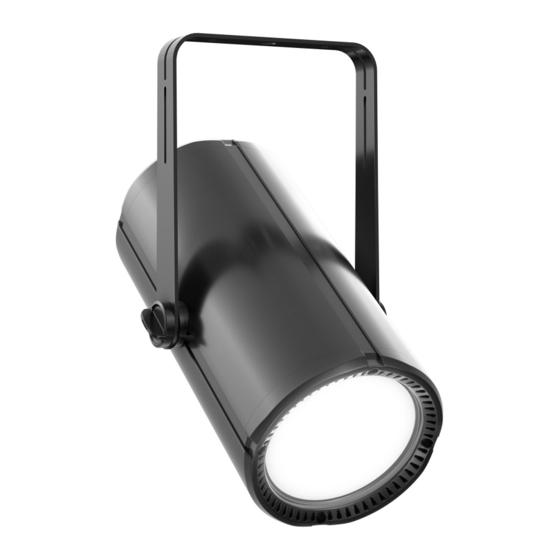
    EINFÜHRUNG DAYLIGHT (TAGESLICHT) PENDANT SCHEINWERFER MIT W-DMX™ CLH1D (schwarzes Gehäuse) CLH1DWH (weißes Gehäuse) TUNGSTEN (WARMWEISS) PENDANT SCHEINWERFER MIT W-DMX™ CLH1T (schwarzes Gehäuse) CLH1TWH (weißes Gehäuse) STEUERUNGSFUNKTIONEN • 1-Kanal, 2-Kanal und 4-Kanal DMX-Steuerung • W-DMX™ • Master/Slave-Betrieb • Standalone Funktionen EIGENSCHAFTEN •...
  • Seite 40: Anschlüsse, Bedien- Und Anzeigeelemente

    ANSCHLÜSSE, BEDIEN- UND ANZEIGEELEMENTE ANSCHLUSSTERMINAL Das Anschlussterminal dient der Spannungs- und Signalversorgung bei der Festinstallation. Ach- ten Sie auf die Sicherheitshinweise zur Verkabelung des Terminals unter ANSCHLUSSTERMINAL VERKABELN! FUSE Sicherungshalter für 5 x 20 mm Sicherungen. ACHTUNG: Ersetzen Sie die Sicherung ausschließ- lich durch eine Sicherung des gleichen Typs und mit gleichen Werten.
  • Seite 41: Dip-Schalter

    DIP-SCHALTER Acht DIP-Schalter für die Basiskonfiguration des Scheinwerfers. Für die vollständige Konfiguration des Scheinwerfers benötigen Sie die optional erhältliche Remote-Einheit UNICON. DIP Switch Funktion Erklärung 1 ON Auswahl des RJ45 Aderpaars Das eingehende DMX-Signal kann auf eines der 4 verfügbaren Aderpaare geroutet werden 2 ON 3 ON 4 ON...
  • Seite 42 STATUS-LED Die LED zeigt den aktuellen Status des Scheinwerfers bei der Ansteuerung per Kabel und per W-DMX an. Ansteuerung per Kabel (DMX, RJ45) Ansteuerung per W-DMX™ LED leuchtet DMX-Signal liegt an LED blinkt W-DMX aktiviert permanent blau rot mit ca. 1 Hz LED blinkt blau kein DMX-Signal LED blinkt...
  • Seite 43: Anschlussterminal Verkabeln

    ANSCHLUSSTERMINAL VERKABELN GEFAHR: Das Öffnen des Scheinwerfers und das Anschließen von Kabeln an das Anschlussterminal erfordert detailliertes Fachwissen und darf nur von speziell ausgebil- deten Personen durchgeführt werden! Wenn Sie diese Qualifikation nicht haben, versuchen Sie nicht, den Scheinwerfer zu öffnen und Kabel selbst anzuschließen, sondern nutzen Sie die Hilfe von professionellen Unternehmen! Der Hersteller haftet nicht für Sach- und Personenschäden, die durch unsachgemäße Handhabung entstehen!
  • Seite 44: Bedienung Per Remote-Einheit Unicon

    Klemmmuttern der Kabeldurchführungen festziehen. BEDIENUNG PER REMOTE-EINHEIT UNICON Die Bedienung der Scheinwerfermodelle H1 D und H1 T erfolgt auf identische Art und Weise. Der Einfachheit halber wird im nachfolgenden Text und in den Darstellungen die Modellbezeichnung H1 D verwendet.
  • Seite 45 Encoder bzw. auf das Häkchensymbol  im Display. Daraufhin wird eine Liste aller ange- schlossener RDM-Geräte angezeigt (im Beispiel H1 D/H1 D und H1 FC/H1 FC, der erste Teil des angezeigten RDM-Geräts zeigt das Gerätemodell, der zweite Teil hinter „/“ ist eine zusätzliche Bezeichnung, diese kann zur leichteren Identifizierung individuell im Menüpunkt Label angepasst...
  • Seite 46 Anzahl der Kanäle im aktuellen DMX-Modus Sensor LED-Temperatur (zum Anzeigen  drücken) Fixture Menu Individuelles Cameo Gerätemenü zum Editieren der Einstellungen (siehe GERÄTEMENÜ (Fixture Menu)) Label Wählen Sie im Menü RDM/Fixture den Punkt Label aus und bestätigen die Auswahl, um das RDM-Gerät individuell zu kennzeichnen.
  • Seite 47: Dmx-Startadresse Einstellen

    GERÄTEMENÜ (Fixture Menu): Auswahl des gewünschten Menüpunkts mit  bzw.  oder durch Drehen des Encoders, bestäti- gen mit  oder durch Drücken des Encoders. Zurück mit  oder BACK. Wert bzw. Status einstellen mit  bzw.  oder durch Drehen des Encoders, bestätigen mit  oder durch Drücken des Encoders.
  • Seite 48: Timer-Funktion

    Wählen Sie Stand Alone aus, bestätigen die Auswahl, wählen dann Static aus und bestätigen abermals die Auswahl. Wählen Sie nun den Menüpunkt aus, den Sie bearbeiten möchten und bestätigen die Auswahl. Stellen Sie im ausgewählten Menüpunkt den gewünschten Wert von 000 bis 255 ein und bestätigen die Eingabe.
  • Seite 49 SYSTEMEINSTELLUNGEN (Settings) Wählen Sie Settings aus und bestätigen die Auswahl. Daraufhin gelangen Sie in das Untermenü zum Einstellen der Untermenüpunkte (siehe Tabelle): Settings DMX Fail = Betriebszustand bei Hold letzter Befehl wird gehalten DMX-Signal-Unter- brechung Blackout aktiviert Blackout Full On 100% Output Dimmer = Dimmerkurve...
  • Seite 50 Calibra- = Einstellen der Maxi- White Betriebsartübergreifende Helligkeitsein- tion malhelligkeit stellung mit Werten von 000 - 255 Power = Betriebsmodus Constant Konstante Helligkeit über lange Zeiträume Maximum Maximale Helligkeit Factory = Zurücksetzen auf Reset? Zurücksetzen auf Werkseinstellungen: Reset Werkseinstellungen Reset durchführen:  oder Encoder drücken Abbrechen: ...
  • Seite 51: Streuscheiben

    STREUSCHEIBEN Im Lieferumfang des Scheinwerfers befinden sich 3 Streuscheiben (1x vormontiert), die über ein unterschiedliches Abstrahlverhalten verfügen (20° (Narrow), 35° (Middle), 45°(Wide). Der Abstrahlwinkel des Scheinwerfers kann somit individuell auf 20°, 35°, oder 45° eingestellt werden. Lösen Sie die vier Schrauben (A) vom Haltering auf der Vorderseite des Scheinwerfers mit Hilfe eines geeigneten Werkzeugs und nehmen den Haltering vom Scheinwerfer.
  • Seite 52: Traversenmontage

    TRAVERSENMONTAGE GEFAHR: Überkopfmontage erfordert umfassende Erfahrung, einschließlich der Berech- nung der Grenzwerte für die Arbeitslast, des verwendeten Installationsmaterials und der regelmäßigen Sicherheitsüberprüfung aller Installationsmaterialien und Scheinwerfer! Wenn Sie diese Qualifikationen nicht haben, versuchen Sie nicht, eine Installation selbst durchzuführen, sondern nutzen Sie die Hilfe von professionellen Unternehmen! Es besteht die Gefahr, dass sich nicht korrekt montierte und gesicherte Geräte lösen und herabfallen.
  • Seite 53 Für die hängende Installation kann der Montagebügel komplett vom Scheinwerfer demontiert werden, Resultat ist eine gleichmäßige und dezente Optik. Lösen Sie hierfür die beiden Griffschrauben (A) vom Montagebügel und entfernen ihn. Die Sockel (B) auf beiden Seiten des Scheinwerfers werden mit Hilfe eines geeigneten Werkzeugs gelöst, verdecken Sie die Montagelöcher (C) mit Hilfe der verschiebbaren Metallschienen in den Nuten (D).
  • Seite 54: Pflege, Wartung Und Reparatur

    PFLEGE, WARTUNG UND REPARATUR Um die einwandfreie Funktion des Geräts auf Dauer zu gewährleisten, muss es regelmäßig ge- pflegt und bei Bedarf gewartet werden. Der Pflege- bzw. Wartungsbedarf steht in Abhängigkeit der Nutzungsintensität und -umgebung. Wir empfehlen generell eine Sichtprüfung vor jeder Inbetriebnahme. Weiterhin empfehlen wir alle 500 Betriebsstunden, oder bei geringerer Nutzungsintensität spätestens nach Ablauf eines Jahres alle unten genannten und zutreffenden Pflegemaßnahmen durchzuführen.
  • Seite 55: Optionales Zubehör

    HINWEIS! Unsachgemäß ausgeführte Wartungsarbeiten können den Gewährleistungsanspruch beeinträchtigen. HINWEIS! Bei vom Hersteller vorgesehenen Um- oder Nachrüstsets beachten Sie unbedingt die beiliegende Einbauanleitung. OPTIONALES ZUBEHÖR CLIREMOTE RDM-basierte Remote-Einheit UNICON mit Touch-Farb-Display, DMX- und RJ45-Anschluss CLH1CKB (SCHWARZ) CLH1CKW (WEISS) Deckeneinbauset für H1 Scheinwerfer...
  • Seite 56 CLH1HALFSNOOT (SCHWARZ) CLH1HALFSNOOTWH (WEISS) Halbblendschutz „Half Snoot“ für H1 Scheinwerfer CLH1SNOOT (SCHWARZ) CLH1SNOOTWH (WEISS) Vollblendschutz „Snoot“ für H1 Scheinwerfer CLH1WALLMOUNT (SCHWARZ) CLH1WALLMOUNTWH (WEISS) Wandhalterung für H1 Scheinwerfer...
  • Seite 57: Technische Daten

    TECHNISCHE DATEN Artikelnummer: CLH1D(WH) CLH1T(WH) Produktart: LED-Scheinwerfer LED-Scheinwerfer Typ: Installationsscheinwerfer Installationsscheinwerfer Farbspektrum: Tageslicht 6500K Warmweiß 3000K LED Anzahl: LED Typ: 80W COB 80W COB LED PWM Frequenz: 800 Hz, 1200 Hz, 2000 Hz, 800 Hz, 1200 Hz, 2000 Hz, 3600 Hz, 12 kHz, 2 kHz 3600 Hz, 12 kHz, 25 kHz (einstellbar) (einstellbar)
  • Seite 58: Mindestabstand Zur Beleuchteten Fläche

    Abmessungen 128 x 255 mm 128 x 255 mm (Ø x L, ohne Montagebü- gel): Gewicht 2,8 kg 2,8 kg (inkl. Montagebügel): Lieferumfang (inkl): Montagebügel (vormontiert) Montagebügel (vormontiert) 3x Streuscheibe (1x vormon- 3x Streuscheibe (1x vormon- tiert) tiert) Zubehör (optional): Deckeneinbaukit Deckeneinbaukit Wandmontagehalterung...
  • Seite 59: Herstellererklärungen

    HERSTELLERERKLÄRUNGEN HERSTELLERGARANTIE & HAFTUNGSBESCHRÄNKUNG Adam Hall GmbH, Adam-Hall-Str. 1, D-61267 Neu Anspach / E-Mail Info@adamhall.com / +49 (0)6081 / 9419-0. Unsere aktuellen Garantiebedingungen und Haftungsbeschränkung finden Sie unter: https://cdn-shop.adamhall.com/media/pdf/Manufacturers-Declarations-CAMEO_DE_EN_ES_ FR.pdf. Im Servicefall wenden Sie sich an Ihren Vertriebspartner. CE-KONFORMITÄT Hiermit erklärt die Adam Hall GmbH, dass dieses Produkt folgender Richtlinie entspricht (soweit zutreffend): Niederspannungsrichtlinie (2014/35/EU) EMV-Richtlinie (2014/30/EU)
  • Seite 60: Français

    Cet appareil a été conçu et produit suivant des exigences de qualité très strictes pour fonctionner pendant de nombreuses années. Veuillez lire attentivement ce manuel d’utilisation pour pouvoir utiliser rapidement et de manière optimale votre nouveau produit Cameo Light. Vous trouverez de plus amples informations sur Cameo Light sur notre site Web CAMEOLIGHT.COM.
  • Seite 61: Consignes De Sécurité

    Ce symbole indique un danger susceptible de provoquer une décharge électrique. Ce symbole indique une zone ou une situation dangereuse. Ce symbole indique des dangers liés à des surfaces chaudes. Ce symbole signale des dangers liés à des sources lumineuses intenses. Ce symbole indique que l’appareil ne contient aucune pièce remplaçable par l’utili- sateur.
  • Seite 62 AVERTISSEMENT : 1. L’appareil ne doit pas être mis en service s’il présente des dommages apparents. 2. L’appareil ne doit être installé que lorsqu’il est hors tension. 3. Si le câble réseau de l’appareil est endommagé, l’appareil ne doit pas être mis en service.
  • Seite 63 AVERTISSEMENT : 1. Utilisez uniquement cet appareil conformément à l’usage prévu. 2. Utilisez uniquement cet appareil avec les accessoires recommandés et prévus par le fabricant. 3. Lors de l’installation, veillez à respecter les prescriptions de sécurité en vigueur dans votre pays. 4.
  • Seite 64 ATTENTION : 1. N’installez et n’utilisez pas cet appareil à proximité de radiateurs, d’accumu- lateurs thermiques, de fours ou d’autres sources de chaleur. Veillez à installer l’appareil de façon à assurer en permanence un refroidissement suffisant et à éviter une surchauffe. 2.
  • Seite 65 TRANSMISSION DE SIGNAUX PAR RADIO (par ex. W-DMX ou systèmes audio sans fil) : La qualité et la performance des transmissions de signaux sans fil dépendent généralement des conditions ambiantes. Les éléments suivants ont par exemple une influence sur la portée et la stabilité des signaux : Écrans (par ex.
  • Seite 66: Consignes Pour Les Appareils D'installation Intérieure

    TRANSMISSION DE SIGNAL PAR W-DMX AVERTISSEMENT : en règle générale, la transmission DMX sans fil ne doit pas être utilisée pour des applications présentant des facteurs de sécurité susceptibles d’entraîner des dommages corporels ou matériels en cas de défaillance. Ceci s’applique en particulier aux structures de scènes ou de traverses mobiles, aux moteurs/dispositifs de levage commandés par DMX ou aux dispositifs de levage destinés au fonctionnement de monte-plateaux, de systèmes hydrauliques ou de composants mobiles similaires fonctionnant en mode DMX.
  • Seite 67: Présentation

    PRÉSENTATION PROJECTEUR À LUMIÈRE DU JOUR SUSPENDU AVEC W-DMX™ CLH1D (boîtier noir) CLH1DWH (boîtier blanc) PROJECTEUR À LUMIÈRE TUNGSTÈNE (BLANC CHAUD) SUSPENDU AVEC W-DMX™ CLH1T (boîtier noir) CLH1TWH (boîtier blanc) FONCTIONS DE PILOTAGE • Pilotage en mode DMX sur 1 canal, 2 canaux et 4 canaux •...
  • Seite 68: Raccordements, Éléments De Commande Et D'affichage

    RACCORDEMENTS, ÉLÉMENTS DE COMMANDE ET D’AFFICHAGE BORNE DE RACCORDEMENT La borne de raccordement sert à l’alimentation électrique et l’alimentation en signaux en cas d’in- stallation fixe. Respecter les consignes de sécurité relatives au câblage de la borne présentées à la section CÂBLAGE DE LA BORNE DE RACCORDEMENT ! FUSE (FUSIBLE) Porte-fusible pour fusibles de 5 x 20 mm.
  • Seite 69: Commutateurs Dip

    COMMUTATEURS DIP Huit commutateurs DIP pour la configuration de base du projecteur. Pour une configuration com- plète du projecteur, vous avez besoin de l’unité CL UNICON de commande à distance disponible en option. Commuta- Fonction Explications teur DIP 1 ON Sélection de la paire de con- Le signal DMX entrant peut être acheminé...
  • Seite 70 LED D’ÉTAT La LED indique l’état actuel du projecteur lors du pilotage par câble et via W-DMX. Pilotage par câble (DMX, RJ45) Pilotage via W-DMX™ LED allumée Signal DMX présent LED clignote W-DMX activé en bleu permanent en rouge à env. 1 Hz LED clignote en bleu Pas de signal DMX LED clignote Couplage interrompu...
  • Seite 71: Câblage De La Borne De Raccordement

    CÂBLAGE DE LA BORNE DE RACCORDEMENT DANGER : L’ouverture du projecteur et le raccordement de câbles sur la borne de raccordement exigent des connaissances détaillées et ne doivent être effectués que par des personnes spécialement formées à cet effet ! Sans les qualifications requises, ne pas essayer d’ouvrir le projecteur et de raccorder soi-même les câbles, mais faire appel à...
  • Seite 72 Desserrer les 2 vis de fixation du bornier sur lequel sont connectés les câbles d’alimentation électrique et retirer le bornier de la borne correspondante (raccordement sur bornier D). Utiliser un embout approprié pour les extrémités de câbles dénudées et raccorder les câbles du cordon d’al- imentation à...
  • Seite 73: Commande Par Unité De Commande À Distance Cl Unicon

    COMMANDE PAR UNITÉ DE COMMANDE À DISTANCE CL UNICON Les modèles de projecteurs H1 D et H1 T fonctionnent de manière similaire. Pour des raisons de simplicité, la désignation de modèle H1 D est utilisée dans le texte suivant et dans les représenta- tions. FONCTIONS DES ÉLÉMENTS DE COM- MANDE Display...
  • Seite 74 Mode DMX actuel (peut être modifié dans l’option de menu) DMX Slots : Nombre de canaux en mode DMX actuel Sensor : Température de la LED (appuyer sur  pour afficher) Fixture Menu : Menu personnalisé de l’appareil Cameo pour la définition des réglages (voir MENU DE L’APPAREIL (Fixture Menu))
  • Seite 75 Label (Étiquette) Dans le menu RDM/Fixture, sélectionnez l’option Label et validez la sélection pour identifier individuellement l’appareil RDM. Sélectionner un caractère ou une  ou  ou tourner commande : l’encodeur Restaurer la désignation après la Reset dernière sauvegarde : Space Insérer des espaces : Supprimer les caractères à...
  • Seite 76: Fonction De Temporisation

    SÉLECTION DU MODE DMX Sélectionnez le mode DMX, validez la sélection, puis sélectionnez le mode DMX souhaité et validez la sélection. MODE DE FONCTIONNEMENT STAND ALONE STATIC De façon similaire à un dispositif de commande DMX, le mode Standalone (autonome) Static permet de régler directement sur l’appareil les fonctions variateur, variateur précis et stroboscope (Strobe) avec des valeurs comprises entre 000 et 255.
  • Seite 77 Sélectionnez Stand Alone, confirmez la sélection, puis sélectionnez Timer et confirmez à nou- veau la sélection. Sous l’option Switch, sélectionnez On et validez. Pour accéder aux réglages individuels de la temporisation, sélectionnez Fade In, Dwell Time ou Fade Out et validez la sélection Vous pouvez maintenant régler la valeur souhaitée.
  • Seite 78 INFORMATIONS SYSTÈME (SysInformation) Sélectionnez SysInformation et validez la sélection. Settings DMX Fail = État de fonctionne- Hold Maintien de la dernière commande ment en cas d’in- terruption du signal Blackout Active la fonction Blackout Full On Sortie à 100 % Dimmer = Courbe de dimmer Linear L’intensité...
  • Seite 79 Vous accédez alors au sous-menu permettant d’accéder aux informations système (voir tableau) : SysInformation Firmware = Affichage du micrologiciel de Firmware l’appareil V1.xx Temperature = Affichage de la température de xxx °C / xxx °F l’unité à LED Unit Celsius (= af- fichage en degrés Celsius) Unit Fahrenheit...
  • Seite 80: Diffuseurs

    DIFFUSEURS Le projecteur est fourni avec 3 diffuseurs (1x prémonté) dotés de différents angles de dispersion (20° (narrow), 35° (Middle), 45° (Wide)). L’angle de dispersion du projecteur peut ainsi être réglé individuellement sur 20°, 35° ou 45°. Desserrez les quatre vis (A) de l’anneau de maintien situé sur l’avant du projecteur à l’aide d’un outil approprié...
  • Seite 81: Montage Sur Traverse

    MONTAGE SUR TRAVERSE DANGER : Le montage tête en bas requiert des compétences poussées, notamment pour le calcul des valeurs limites pour la charge de service, le matériel d’installation utilisé et le contrôle de sécurité à effectuer régulièrement sur l’ensemble du matériel d’installation et sur le projecteur ! Sans les qualifications requises, ne pas essayer d’effectuer soi-même l’installation, mais faire appel à...
  • Seite 82 Pour l’installation suspendue, il est possible de démonter entièrement l’étrier de montage du projecteur. L’aspect devient ainsi homogène et discret. Desserrer pour cela les deux vis-poignées (A) de l’étrier de montage et retirer l’étrier. Les supports (B) des deux côtés du projecteur se démontent à l’aide d’un outil approprié. Cacher ensuite les trous de fixation (C) à...
  • Seite 83: Entretien, Maintenance Et Réparation

    ENTRETIEN, MAINTENANCE ET RÉPARATION Pour garantir le bon fonctionnement de l’appareil à long terme, l’entretien et, si nécessaire, la maintenance doivent être effectués régulièrement. Les besoins en entretien et en maintenance dépendent de l’intensité et de l’environnement d’utilisation. Nous recommandons de procéder à un contrôle visuel avant chaque mise en service. En outre, nous recommandons de prendre toutes les mesures d’entretien pertinentes indiquées ci-dessous toutes les 500 heures de fonctionnement ou, en cas d’intensité...
  • Seite 84: Accessoires En Option

    REMARQUE ! Les travaux de maintenance et de réparation ne doivent être effec- tués que par du personnel spécialisé et suffisamment qualifié. En cas de doute, adressez-vous à un atelier spécialisé. REMARQUE ! Des travaux d’entretien effectués de manière non conforme peuvent affecter le droit à...
  • Seite 85 CLH1HALFSNOOT (NOIR) CLH1HALFSNOOTWH (BLANC) Demi-protection anti-éblouissement « Half Snoot » pour projecteurs H1 CLH1SNOOT (NOIR) CLH1SNOOTWH (BLANC) Protection anti-éblouissement intégrale « Snoot » pour projecteurs H1 CLH1WALLMOUNT (NOIR) CLH1WALLMOUNTWH (BLANC) Support mural pour projecteurs H1...
  • Seite 86: Caractéristiques Techniques

    CARACTÉRISTIQUES TECHNIQUES Référence : CLH1D(WH) CLH1T(WH) Catégorie de produit : Projecteur à LED Projecteur à LED Type : Projecteur d’installation fixe Projecteur d’installation fixe Spectre de couleurs : Lumière du jour 6500 K Blanc chaud 3000 K Nombre de LED : Type de LED : COB 80 W COB 80 W Fréquence du signal PWM 800 Hz, 1200 Hz, 2000 Hz, 800 Hz, 1200 Hz, 2000 Hz,...
  • Seite 87: Distance Minimale Par Rapport À La Surface Éclairée

    Distance minimale par 0,5 m 0,5 m rapport à la surface éclairée : Distance minimale par 0,3 m 0,3 m rapport aux matériaux nor- malement inflammables : Dimensions 128 x 255 mm 128 x 255 mm (Ø x L, sans étrier de montage) : Poids 2,8 kg 2,8 kg (avec étrier de montage) : Contenu de la livraison Étrier de montage (prémonté) Étrier de montage (prémonté) (inclus) :...
  • Seite 88: Déclarations Du Fabricant

    APPAREIL : 1. Cet appareil est soumis à la directive européenne sur les déchets d’équipements électriques et électroniques dans sa version actuelle. Directive DEEE Déchets d’équipements électriques et électroniques. Les appareils usagés ne doivent pas être jetés avec les ordures ménagères. L’appareil usagé doit être éliminé par une entreprise d’élimination des déchets agréée ou par un organisme communal de traitement des déchets.
  • Seite 89: Español

    Lea atentamente el presente manual de in- strucciones con el fin de poder usar rápidamente y de forma óptima su nuevo producto de Cameo Light. Puede encontrar más información sobre Cameo Light en nuestro sitio web CAMEOLIGHT.
  • Seite 90: Instrucciones De Seguridad

    Este símbolo indica peligros que pueden causar una descarga eléctrica. Este símbolo indica puntos de peligro o situaciones peligrosas. Este símbolo indica peligros por superficies calientes. Este símbolo indica peligros debido a fuentes de luz intensas. Este símbolo indica que en el equipo no hay piezas que pueda sustituir el usuario. Este símbolo identifica información complementaria sobre el uso del producto.
  • Seite 91 ATENCIÓN: 1. No poner en marcha el equipo si ha estado sometido a fuertes fluctuaciones de temperatura (por ejemplo, tras su transporte). La humedad y el agua condensa- da pueden dañar el equipo. Encender el equipo únicamente después de que su temperatura haya alcanzado la temperatura ambiente.
  • Seite 92 ADVERTENCIA: 1. Utilizar el equipo únicamente de la forma prevista. 2. Utilizar el equipo solo con los accesorios previstos y recomendados por el fabri- cante. 3. Durante la instalación, hay que tener en cuenta los reglamentos de seguridad vigentes en su país. 4.
  • Seite 93 ATENCIÓN: 1. No instalar ni poner a funcionar el equipo cerca de radiadores, acumuladores tér- micos, hornos u otras fuentes de calor. Asegurarse de que el equipo siempre esté instalado de modo que reciba suficiente refrigeración y no pueda sobrecalentarse. 2.
  • Seite 94 TRANSMISIÓN DE SEÑALES POR RADIO (por ejemplo, W-DMX o sistemas de audio inalámbricos): La calidad y el rendimiento de las transmisiones inalámbricas de señales dependen, por lo general, de las condiciones ambientales. Elementos que influyen en el alcance y la estabilidad de la señal: barreras (p.
  • Seite 95: Instrucciones Para Los Equipos De Instalación Fija En Interiores

    TRANSMISIÓN DE SEÑALES POR W-DMX ADVERTENCIA: En general, la transmisión DMX inalámbrica no se puede utilizar para aplicaciones con factores relevantes para la seguridad que puedan provocar daños personales o materiales en caso de fallo. Esto afecta especialmente a las estructuras móviles para escenarios o truss, a los motores/elevadores controlados por DMX o a los dispositivos de elevación para el manejo de torres elevadoras, sistemas hidráulicos o componentes móviles similares accionados por DMX.
  • Seite 96: Introducción

    INTRODUCCIÓN FOCO DAYLIGHT (LUZ DIURNA) PENDANT CON W-DMX™ CLH1D (carcasa negra) CLH1DWH (carcasa blanca) FOCO TUNGSTEN (BLANCO CÁLIDO) PENDANT CON W-DMX™ CLH1T (carcasa negra) CLH1TWH (carcasa blanca) FUNCIONES DE CONTROL • Control DMX de 1 canal, 2 canales y 4 canales •...
  • Seite 97: Conexiones, Elementos De Manejo Y Elementos De Visualización

    CONEXIONES, ELEMENTOS DE MANEJO Y ELEMENTOS DE VISUALIZACIÓN TERMINAL DE CONEXIONES El terminal de conexiones sirve para suministrar la tensión y la señal en instalaciones fijas. Para el cableado del terminal, tenga en cuenta las indicaciones de seguridad del apartado CABLEADO DEL TERMINAL DE CONEXIONES.
  • Seite 98: Interruptor Dip

    INTERRUPTOR DIP Ocho interruptores DIP para la configuración básica del foco. La configuración completa del foco requiere el mando a distancia opcional UNICON. Interruptor Función Aclaración 1 ON Selección del par de hilos La señal DMX entrante se puede enrutar por RJ45 uno de los 4 pares de hilos disponibles 2 ON...
  • Seite 99: Led De Estado

    LED DE ESTADO El LED indica el estado actual del foco al controlarlo por cable y mediante W-DMX. Control por cable (DMX, RJ45) Control mediante W-DMX™ El LED se ilumina Se recibe una señal El LED parpadea W-DMX activado permanentemente en rojo con aprox.
  • Seite 100: Cableado Del Terminal De Conexiones

    CABLEADO DEL TERMINAL DE CONEXIONES PELIGRO: La apertura del foco y la conexión de cables al terminal de conexiones requieren conocimientos técnicos precisos y solo pueden ser efectuadas por personal que disponga de la cualificación específica pertinente. Si no está cualificado para ello, no intente abrir el foco ni conectar cables.
  • Seite 101: Manejo Con El Mando A Distancia Unicon

    MANEJO CON EL MANDO A DISTANCIA UNICON El manejo de los focos de los modelos H1 D y H1 T es idéntico. Para mayor comodidad, en el texto y en las ilustraciones siguientes se utiliza la denominación de modelo H1 D.
  • Seite 102  en la pantalla. Seguidamente aparecerá una lista de todos los dispositivos RDM conectados (en el ejemplo, H1 D/H1 D y H1 FC/H1 FC, la primera parte del dispositivo RDM mostrado indica el modelo del dispositivo, mientras que la segunda parte detrás de «/»...
  • Seite 103 Sensor Temperatura LED (pulsar  para visualizar) Fixture Menu Menú individual del dispositivo Cameo para editar los ajustes (véase MENÚ DEL DISPOSITIVO (Fixture Menu)) Label En el menú RDM/Fixture, seleccione la opción Label (Etiqueta) y confirme la selección para per- sonalizar el dispositivo RDM.
  • Seite 104 CONFIGURACIÓN DE LA DIRECCIÓN INICIAL DMX Seleccione DMX Address, confirme la selección, ajuste la dirección DMX deseada y confirme la entrada. SELECCIONAR EL MODO DMX Seleccione DMX Mode, confirme la selección, después seleccione el modo DMX deseado y confirme la selección. MODO AUTÓNOMO STATIC De forma similar a la configuración con un equipo de control DMX, el modo autónomo Static permite ajustar las funciones de atenuación (Dimmer), atenuación fina (Dimmer Fine) y estrobo...
  • Seite 105: Función De Temporizador

    FUNCIÓN DE TEMPORIZADOR La función de temporizador permite el control por tiempo del modo operativo autónomo «Static» ajustando el tiempo de aparición (Fade In) de 0,5 segundos a 24 horas, el tiempo de permanencia (Dwell Time) de 0,5 segundos a 24 horas e ilimitado (limitless) y el tiempo de desaparición (Fade Out) de 0,5 segundos a 24 horas.
  • Seite 106 Después, accederá al submenú para la configuración de las opciones del submenú, (consulte la tabla): Settings DMX Fail = Estado operativo en Hold Se mantendrá el último comando caso de interrupción de la señal DMX Blackout Activa el Blackout Full On 100% de potencia Dimmer = Curva de atenuación Linear...
  • Seite 107 INFORMACIÓN DEL SISTEMA (SysInformation) Seleccione SysInformation y confirme la selección. Después, accederá al submenú para acceder a la información del sistema (consulte la tabla): SysInformation Firmware = Visualización de la versión del Firmware firmware del dispositivo V1.xx Temperature = Visualización de la temperatura de xxx°C / xxx°F la unidad LED Unit Celsius (=...
  • Seite 108: Difusores

    DIFUSORES Con el foco se suministran tres difusores (1 premontado) que generan distintos efectos de dis- persión (un difusor de 20°, Narrow, uno de 35°, Middle, y otro de 45°, Wide). De esa forma, el ángulo de dispersión del foco puede ajustarse de forma individual a 20°, 35°, o 45°.
  • Seite 109: Montaje En Travesaño

    MONTAJE EN TRAVESAÑO PELIGRO: El montaje en altura requiere mucha experiencia, incluido el cálculo de los valores límite de la carga de trabajo, el material de instalación utilizado y las comproba- ciones de seguridad periódicas de todos los focos y materiales de instalación. Si no está cualificado para ello, no intente realizar la instalación por su cuenta, recurra a una empresa profesional.
  • Seite 110 Para la instalación en suspensión se puede desmontar por completo del foco el soporte de monta- je, lo que da lugar a una apariencia uniforme y discreta. Para ello, afloje los dos tornillos de manejo (A) del soporte de montaje y retírelo. Los casquillos (B) a ambos lados del foco se aflojan con una herramienta adecuada, cubra los orificios de montaje (C) con los rieles metálicos deslizantes en las ranuras (D).
  • Seite 111: Cuidado, Mantenimiento Y Reparación

    CUIDADO, MANTENIMIENTO Y REPARACIÓN Para garantizar el correcto funcionamiento del equipo a largo plazo, este se debe revisar perió- dicamente y reparar en caso necesario. Las necesidades de cuidado y mantenimiento dependen de la intensidad y el entorno de uso. Por lo general, recomendamos realizar una inspección visual antes de cada puesta en marcha.
  • Seite 112: Accesorios Opcionales

    ¡AVISO! Los trabajos de mantenimiento realizados indebidamente pueden afectar al derecho de garantía. ¡AVISO! En el caso de los sets de conversión o reequipamiento previstos por el fabricante, hay que tener en cuenta obligatoriamente las instrucciones de montaje adjuntas. ACCESORIOS OPCIONALES CLIREMOTE Unidad remota UNICON basada en RDM con pantalla táctil en color, DMX y conexión RJ45 CLH1CKB (NEGRO)
  • Seite 113 CLH1HALFSNOOT (NEGRO) CLH1HALFSNOOTWH (BLANCO) Semiparasol «Half Snoot» para focos H1 CLH1SNOOT (NEGRO) CLH1SNOOTWH (BLANCO) Parasol completo «Snoot» para focos H1 CLH1WALLMOUNT (NEGRO) CLH1WALLMOUNTWH (BLANCO) Soporte de pared para focos H1...
  • Seite 114: Datos Técnicos

    DATOS TÉCNICOS Número de artículo: CLH1D(WH) CLH1T(WH) Clase de producto: Foco LED Foco LED Tipo: Foco para instalación fija Foco para instalación fija Espectro cromático: Luz diurna 6500 K Blanco cálido 3000 K Cantidad de LED: Tipo de LED: Chip-on-Board de 80 W Chip-on-Board de 80 W Frecuencia de la modu- 800 Hz, 1200 Hz, 2000 Hz,...
  • Seite 115: Distancia Mínima Con Respecto A La Superficie Iluminada

    Clase de protección: IP20 IP20 Distancia mínima con 0,5 m 0,5 m respecto a la superficie iluminada: Distancia mínima con 0,3 m 0,3 m respecto a materiales normalmente inflamables: Dimensiones 128 x 255 mm 128 x 255 mm (Ø x longitud, sin soporte de montaje): Peso 2,8 kg 2,8 kg...
  • Seite 116: Declaraciones Del Fabricante

    EQUIPO: 1. Este equipo está sujeto a la Directiva europea sobre residuos de aparatos eléctricos y electrónicos, en su versión actual. Directiva RAEE sobre residuos de aparatos eléctricos y electrónicos. Los equipos usados no se tiran junto con la ba- sura doméstica.
  • Seite 117: Polski

    Należy uważnie przeczytać niniejszą instrukcję obsługi, aby móc jak najszybciej rozpocząć prawidłową eksploatację nowego urządzenia marki Cameo Light. Więcej informacji o marce Cameo Light można znaleźć na stronie CAMEOLIGHT. COM. INFORMACJE DOTYCZĄCE NINIEJSZEJ INSTRUKCJI OBSŁUGI •...
  • Seite 118: Zasady Bezpieczeństwa

    Ten symbol oznacza zagrożenia, które mogą być przyczyną porażenia prądem elektrycznym. Ten symbol oznacza niebezpieczne miejsca lub sytuacje. Ten symbol oznacza niebezpieczeństwa związane z gorącymi powierzchniami. Ten symbol oznacza niebezpieczeństwa związane z intensywnym źródłem światła. Ten symbol oznacza urządzenie, w którym nie ma części wymienianych przez użytkownika.
  • Seite 119 UWAGA: 1. Nie używać urządzenia, jeśli było ono narażone na duże wahania temperatury (np. po transporcie). Wilgoć i kondensat mogą uszkodzić urządzenie. Włączyć urządze- nie dopiero wtedy, gdy osiągnie temperaturę otoczenia. 2. Sprawdzić, czy napięcie i częstotliwość sieci elektrycznej są zgodne z parametra- mi podanymi na urządzeniu.
  • Seite 120 OSTRZEŻENIE: 1. Używać urządzenia tylko zgodnie z przeznaczeniem. 2. Używać urządzenia wyłącznie z akcesoriami zalecanymi i przewidzianymi przez producenta. 3. Podczas instalacji przestrzegać krajowych przepisów bezpieczeństwa. 4. Po podłączeniu urządzenia należy sprawdzić ułożenie wszystkich kabli, aby uni- knąć szkód lub wypadków spowodowanych np. przez potknięcie. 5.
  • Seite 121 UWAGA: 1. Nie instalować ani nie eksploatować urządzenia w pobliżu grzejników, akumu- latorów ciepła, pieców ani innych źródeł ciepła. Upewnić się, że urządzenie jest zawsze instalowane w taki sposób, aby zapewnić wystarczające chłodzenie i nie dopuścić do przegrzania. 2. W pobliżu urządzenia nie umieszczać źródeł zapłonu, takich jak zapalone świece. 3.
  • Seite 122 TRANSMISJA SYGNAŁÓW DROGĄ RADIOWĄ (np. W-DMX lub radiowe syste- my audio): Jakość i wydajność transmisji bezprzewodowej zależą głównie od warunków oto- czenia. Na zasięg i stabilność sygnału mają wpływ m.in.: Ekranowanie (np. mury, konstrukcje metalowe, woda) Wysokie poziomy emisji fal radiowych (np. silne sieci Wi-Fi) Zakłócenia Promieniowanie elektromagnetyczne (np.
  • Seite 123: Uwagi Dotyczące Urządzeń Służących Do Montażu We Wnętrzach

    TRANSMISJA SYGNAŁÓW W W-DMX OSTRZEŻENIE: Ogólnie rzecz biorąc, bezprzewodowa transmisja DMX nie może być stosowana, gdy występują czynniki wpływające na bezpieczeństwo, które w przypadku awarii mogą spowodować obrażenia osób lub szkody materialne. Dotyczy to w szczególności ruchomych konstrukcji scenicznych lub kratownic, sil- ników/podnośników sterowanych przez DMX lub urządzeń...
  • Seite 124: Wprowadzenie

    WPROWADZENIE REFLEKTOR TYPU DAYLIGHT (ŚWIATŁO DZIENNE), WISZĄCY, Z OBSŁUGĄ W-DMX™ CLH1D (czarna obudowa) CLH1DWH (biała obudowa) REFLEKTOR TYPU TUNGSTEN (CIEPŁA BIEL), WISZĄCY, Z OBSŁUGĄ W-DMX™ CLH1T (czarna obudowa) CLH1TWH (biała obudowa) FUNKCJE STEROWANIA • 1-kanałowe, 2-kanałowe, 4-kanałowe sterowanie DMX • W-DMX™ •...
  • Seite 125: Przyłącza, Elementy Obsługi I Wskaźniki

    PRZYŁĄCZA, ELEMENTY OBSŁUGI I WSKAŹNIKI LISTWA PRZYŁĄCZENIOWA Listwa przyłączeniowa służy do zasilania napięciem i transmisji sygnału dla instalacji stałej. Należy przestrzegać wskazówek bezpieczeństwa dotyczących okablowania listwy, opisanych w punkcie OKABLOWANIE LISTWY PRZYŁĄCZENIOWEJ! BEZPIECZNIK Oprawa na bezpieczniki 5 x 20 mm. UWAGA: Bezpiecznik należy wymieniać wyłącznie na bez- piecznik tego samego typu i o tych samych parametrach.
  • Seite 126 PRZEŁĄCZNIK DIP Osiem przełączników DIP do podstawowej konfiguracji reflektora. Do kompletnej konfiguracji reflektora potrzebny jest opcjonalny moduł zdalnego sterowania UNICON. Przełącznik Tryb pracy Wyjaśnienie 1 ON Wybór pary żył RJ45 Wchodzący sygnał DMX może być kierowany do jednej z 4 dostępnych par żył 2 ON 3 ON 4 ON...
  • Seite 127: Dioda Stanu

    DIODA STANU Dioda LED wskazuje bieżący stan reflektora podczas sterowania za pomocą kabla i W-DMX. Sterowanie za pośrednictwem kabla Sterowanie przez W-DMX™ (DMX, RJ45) Dioda LED miga Aktywacja W-DMX Dioda LED świeci Sygnał DMX na czerwono z częs- ciągłym niebieskim dostępny totliwością...
  • Seite 128: Okablowanie Listwy Przyłączeniowej

    OKABLOWANIE LISTWY PRZYŁĄCZENIOWEJ NIEBEZPIECZEŃSTWO: Otwieranie reflektora i podłączanie przewodów do listwy zaciskowej wymaga szczegółowej wiedzy technicznej i może być wykonywane tylko przez specjalnie przeszkolone osoby! Użytkownik bez odpowiednich kwalifikacji nie powinien tego robić samodzielnie, lecz skorzystać z pomocy profesjonalnych firm! Producent nie ponosi odpowiedzialności za szkody materialne lub obrażenia ciała spowodowane niewłaściwą...
  • Seite 129: Obsługa Za Pomocą Jednostki Zdalnej Unicon

    Chronić listwę zaciskową przed naprężeniami mechanicznymi, dokręcając nakrętki przepustów kablowych. OBSŁUGA ZA POMOCĄ JEDNOSTKI ZDALNEJ UNICON Obsługa reflektorów H1 D i H1 T odbywa się w ten sam sposób. Dla uproszczenia w poniższym tekście i na ilustracjach zastosowano oznaczenie modelu H1 D. FUNKCJE ELEMENTÓW STERUJĄCYCH...
  • Seite 130 H1 D/H1 D i H1 FC/H1 FC, pierwsza część wyświetlanego urządzenia RDM pokazuje model urządzenia, druga część po ukośniku jest dodatkowym oznaczeniem, które można dostoso- wać w celu ułatwienia identyfikacji w punkcie menu Label). Wybrać H1 D/H1 D i potwierdzić. Zostaną wyświetlone wszystkie informacje i konfiguracje reflektora, które można wywołać i...
  • Seite 131 Liczba kanałów w bieżącym trybie DMX Sensor Temperatura diody LED (nacisnąć , aby wyświetlić) Menu Fixture Indywidualne menu urządzeń Cameo do edycji ustawień (patrz MENU URZĄDZENIA (Fixture Menu)) Labels W menu RDM/Fixture wybrać opcję Label i potwierdzić, aby indywidualnie oznaczyć urządzenie RDM.
  • Seite 132: Ustawianie Adresu Startowego Dmx

    MENU URZĄDZENIA (Fixture Menu): Wybrać żądaną pozycję menu za pomocą przycisku  lub , obracając pokrętło enkodera, potwierdzić przyciskiem  lub naciskając pokrętło. Wrócić, używając przycisku  lub BACK. Ustawić wartość lub status za pomocą przycisku  lub , obracając pokrętło enkodera, potwi- erdzić...
  • Seite 133: Funkcja Timera

    USTAWIANIE TRYBU PRACY STANDALONE STATIC Tryb standalone Static umożliwia, podobnie jak sterownik DMX, ustawienie ściemniacza, ściemni- acza precyzyjnego i stroboskopu (Strobe) bezpośrednio w urządzeniu w przedziale od 000 do 255. Dzięki temu można stworzyć indywidualną scenę bez dodatkowego kontrolera DMX. Wybrać...
  • Seite 134 USTAWIENIA SYSTEMU (Settings) Wybrać opcję Settings i potwierdzić. Następuje przejście do podmenu do ustawiania pozycji podmenu (patrz tabela): Settings DMX Fail = stan roboczy w Hold zachowuje ostatnie polecenie przypadku przerwa- nia sygnału DMX Blackout aktywuje wygaszenie reflektora Full On 100% Output Dimmer = krzywa regulacji...
  • Seite 135 Calibra- = ustawianie maksy- White Ustawienie jasności dla wszystkich try- tion malnej jasności bów pracy z wartościami od 000–255 Power = tryb pracy Constant stała jasność przez długi czas Maximum Maksymalna jasność Factory = przywracanie ust- Reset? Resetowanie do ustawień fabrycznych: Reset awień...
  • Seite 136: Dyfuzory

    DYFUZORY W zestawie reflektora znajdują się 3 dyfuzory (1x wstępnie zmontowany) o różnym kącie rozwar- cia wiązki świetlnej — 20° (Narrow), 35° (Middle), 45° (Wide). Dzięki temu kąt rozwarcia wiązki świetlnej reflektora można indywidualnie ustawić na 20°, 35° lub 45°. Za pomocą odpowiedniego narzędzia odkręcić cztery śruby (A) z pierścienia mocujące- go z przodu reflektora i zdjąć...
  • Seite 137: Montaż Na Kratownicy

    MONTAŻ NA KRATOWNICY NIEBEZPIECZEŃSTWO: Montaż na wysokości wymaga dużego doświadczenia w zakresie obliczania limitów obciążenia, stosowanych materiałów instalacyjnych oraz okresowych przeglądów bezpieczeństwa wszystkich materiałów instalacyjnych i reflektorów! Użytkownik bez odpowiednich kwalifikacji nie powinien wykonywać instalacji samodzielnie, lecz skorzystać z pomocy profesjonalnych firm! Istnieje ryzyko, że nieprawidłowo zamontowane i niezabezpieczone urządzenia poluzują...
  • Seite 138 W przypadku montażu wiszącego uchwyt montażowy można całkowicie zdemontować z reflekto- ra, uzyskując jednolity i dyskretny wygląd. W tym celu należy poluzować dwie śruby (A) uchwytu montażowego i zdjąć go. Gniazda (B) po obu stronach reflektora wyjmuje się za pomocą klucza imbusowego, zakrywając otwory mon- tażowe (C) przesuwanymi metalowymi szynami w rowkach (D).
  • Seite 139: Czyszczenie, Konserwacja I Naprawy

    CZYSZCZENIE, KONSERWACJA I NAPRAWY Aby zapewnić bezawaryjne działanie urządzenia przez długi czas, należy je regularnie czyścić i w razie potrzeby serwisować. Konieczność czyszczenia lub konserwacji zależy od intensywności użytkowania i rodzaju otoczenia. Generalnie zalecamy kontrolę wzrokową przed każdym uruchomieniem. Ponadto zalecamy prze- prowadzanie wszystkich wymienionych poniżej i odpowiednich czynności konserwacyjnych co 500 godzin pracy lub w przypadku mniejszej intensywności użytkowania, najpóźniej po upływie jednego roku.
  • Seite 140: Akcesoria Dodatkowe

    WSKAZÓWKA! Nieprawidłowo wykonane czynności konserwacyjne mogą spowo- dować utratę gwarancji. WSKAZÓWKA! W przypadku zestawów do przebudowy lub doposażenia dostar- czonych przez producenta należy bezwzględnie przestrzegać dołączonej instrukcji montażu. AKCESORIA DODATKOWE CLIREMOTE Oparta na RDM jednostka zdalna UNICON z kolorowym wyświetlaczem dotykowym, DMX i złączem RJ45 CLH1CKB (CZARNY) CLH1CKW (BIAŁY)
  • Seite 141 CLH1HALFSNOOT (CZARNY) CLH1HALFSNOOTWH (BIAŁY) Osłona przeciwodblaskowa „Half Snoot” do reflektorów H1 CLH1SNOOT (CZARNY) CLH1SNOOTWH (BIAŁY) Osłona przeciwodblaskowa „Snoot” do reflektorów H1 CLH1WALLMOUNT (CZARNY) CLH1WALLMOUNTWH (BIAŁY) Uchwyt ścienny do reflektorów H1...
  • Seite 142: Dane Techniczne

    DANE TECHNICZNE Numer artykułu: CLH1D(WH) CLH1T(WH) Rodzaj produktu: Reflektor LED Reflektor LED Typ: Reflektory instalacyjne Reflektory instalacyjne Spektrum kolorów: Światło dzienne 6500K Ciepła biel 3000 K Liczba diod LED: Typ diod LED: 80W COB 80W COB Częstotliwość PWM diody 800 Hz, 1200 Hz, 2000 Hz, 800 Hz, 1200 Hz, 2000 Hz, LED: 3600 Hz, 12 kHz, 2 kHz...
  • Seite 143: Minimalna Odległość Od Powierzchni Oświetlonej

    Stopień ochrony: IP20 IP20 Minimalny odstęp od 0,5 m 0,5 m oświetlonej powierzchni: Minimalny odstęp od 0,3 m 0,3 m materiałów normalnie palnych: Wymiary 128 x 255 mm 128 x 255 mm (Ø x dł., bez uchwytu montażowego): Masa 2,8 kg 2,8 kg (wraz z uchwytem mon- tażowym):...
  • Seite 144: Deklaracje Producenta

    URZĄDZENIE: 1. To urządzenie podlega obowiązującej dyrektywie europejskiej w sprawie zużytego sprzętu elektrycznego i elektronicznego. Dyrektywa WEEE (w sprawie zużytego sprzętu elektrycznego i elektronicznego). Nie wyrzucać zużytych urządzeń wraz z odpadami z gospodarstwa domowego. Zużyte urządzenie należy zutylizować w autoryzowanym zakładzie utylizacji odpadów lub w komunalnym zakładzie utyl- izacji odpadów.
  • Seite 145: Italiano

    Questo dispositivo è stato sviluppato e prodotto secondo elevati standard qualitativi per garan- tirne il regolare funzionamento per molti anni. Leggere attentamente questo manuale d'uso per utilizzare al meglio il nuovo prodotto di Cameo Light. Per maggiori informazioni su Cameo Light, consultare il nostro sito web CAMEOLIGHT.COM.
  • Seite 146: Indicazioni Sulla Sicurezza

    Questo simbolo indica pericoli che possono causare scosse elettriche. Questo simbolo indica punti di pericolo o situazioni pericolose. Questo simbolo indica pericoli dovuti a superfici calde. Questo simbolo indica pericoli dovuti a fonti di luce intense. Questo simbolo indica un dispositivo che non contiene parti sostituibili dall'utente. Questo simbolo indica informazioni complementari sull'utilizzo del prodotto.
  • Seite 147 ATTENZIONE: 1. Non mettere in funzione il dispositivo, se sottoposto a forti sbalzi di temperatura (ad esempio dopo il trasporto). Umidità e condensa potrebbero danneggiare il dispositivo. Accendere il dispositivo solo quando ha raggiunto la temperatura ambiente. 2. Verificare che la tensione e la frequenza della rete elettrica corrispondano ai valori indicati sul dispositivo.
  • Seite 148 AVVERTENZA: 1. Utilizzare il dispositivo unicamente nelle modalità previste. 2. Azionare il dispositivo esclusivamente con gli accessori consigliati e previsti dal produttore. 3. Durante l'installazione, osservare le normative sulla sicurezza in vigore nel proprio Paese. 4. Una volta collegato il dispositivo, verificare tutti i cavi per evitare danni o incidenti, ad esempio per inciampo.
  • Seite 149 ATTENZIONE: 1. Non installare né azionare il dispositivo in prossimità di radiatori, accumulatori termici, stufe o altre fonti di calore. Accertarsi che il dispositivo sia sempre instal- lato in modo che venga raffreddato a sufficienza e non possa surriscaldarsi. 2. Non posizionare fonti di ignizione, come candele accese, nelle vicinanze del dispositivo.
  • Seite 150 TRASMISSIONE DEL SEGNALE VIA RADIO (ad es. W-DMX o sistemi audio): La qualità e le prestazioni della trasmissione wireless del segnale dipendono in genere dalle condizioni ambientali. Influenza sulla portata e sulla stabilità del segnale, ad es.: Schermatura (ad es. muratura, strutture in metallo, acqua) Elevata presenza di onde radio (ad es.
  • Seite 151: Note Per I Dispositivi Da Installazione Interna

    TRASFERIMENTO DEL SEGNALE TRAMITE W-DMX AVVERTENZA: in generale, la trasmissione DMX senza fili non deve essere utilizzata per applicazioni con fattori rilevanti per la sicurezza che possono causare danni a persone o cose in caso di guasto. Ciò vale in particolare per scenografie mobili o traverse, per motori/sollevatori con- trollati da DMX o dispositivi di sollevamento per azionare ascensori da palcoscenico azionati da DMX, sistemi idraulici o componenti mobili analoghi.
  • Seite 152: Introduzione

    INTRODUZIONE PROIETTORE A SOSPENSIONE VERSIONE DAYLIGHT CON W-DMX™ CLH1D (alloggiamento nero) CLH1DWH (alloggiamento bianco) PROIETTORE A SOSPENSIONE IN TUNGSTENO (BIANCO CALDO) CON W-DMX™ CLH1T (alloggiamento nero) CLH1TWH (alloggiamento bianco) FUNZIONI DI CONTROLLO • Controller DMX a 1 canale, 2 canali e 4 canali •...
  • Seite 153: Connettori, Elementi Di Comando E Visualizzazione

    CONNETTORI, ELEMENTI DI COMANDO E VISUALIZZAZIONE TERMINALE DI COLLEGAMENTO Il terminale di collegamento serve per l'alimentazione elettrica e di segnale in caso di installazione permanente. Rispettare le indicazioni sulla sicurezza per il cablaggio del terminale indicate in CABLAGGIO DEL TERMINALE DI COLLEGAMENTO. FUSE Portafusibili per 5 fusibili da 20 mm.
  • Seite 154 DIP SWITCH Otto DIP switch per la configurazione di base del proiettore. Per la configurazione completa del proiettore è necessaria l'unità remota UNICON disponibile come optional. DIP switch Funzionamento Spiegazione 1 ON Selezione della coppia di cavi Il segnale DMX in entrata può essere instradato RJ45 su una delle 4 coppie di fili disponibili 2 ON...
  • Seite 155: Led Di Stato

    LED DI STATO Il LED mostra lo stato corrente del proiettore durante il controllo via cavo e W-DMX. Comando via cavo (DMX, RJ45) Controllo tramite W-DMX™ Il LED si accende Il segnale DMX è Il LED lampeggia W-DMX attivato emettendo una luce presente emettendo una luce blu fissa...
  • Seite 156: Cablaggio Del Terminale Di Collegamento

    CABLAGGIO DEL TERMINALE DI COLLEGAMENTO PERICOLO: l'apertura del proiettore e il collegamento di cavi sul terminale di collega- mento richiedono conoscenze tecniche dettagliate e devono essere effettuati esclusiva- mente da personale opportunamente formato. Se non si dispone di questa qualifica, evitare di aprire il proiettore o di collegare i cavi.
  • Seite 157: Comando Tramite Unità Remota Unicon

    COMANDO TRAMITE UNITÀ REMOTA UNICON I modelli di proiettori H1 D e H1 T funzionano allo stesso modo. Per semplicità, nel testo seguente e nelle illustrazioni viene utilizzata la denominazione del modello H1 D.
  • Seite 158  sul display. Appare un elenco di tutti i dispositivi RDM collegati (nell'esempio H1 D/ H1 D e H1 FC/H1 FC, la prima parte del dispositivo RDM visualizzato mostra il modello del dispos- itivo, la seconda parte dopo "/" è una denominazione aggiuntiva che può essere personalizzata nella voce di menu Label per facilitarne l'identificazione.
  • Seite 159 Numero di canali nella modalità DMX corrente Sensor Temperatura LED (premere  per visualizzare) Fixture Menu Menu individuale del dispositivo Cameo per la modifica delle impostazi- (vedere MENU DEL DISPOSITIVO (Fixture Menu)) Label Nel menu RDM/Fixture, selezionare Label e confermare la selezione per etichettare il dispositivo RDM singolarmente.
  • Seite 160 MENU DISPOSITIVO (Fixture Menu): Selezionare la voce di menu desiderata con  o  oppure ruotando il codificatore, confermare con  o premendo il codificatore. Tornare indietro con  o BACK. Impostare il valore o lo stato con  o  oppure ruotando l'encoder, confermare con  o pre- mendo l'encoder.
  • Seite 161: Funzione Timer

    MODALITÀ DI FUNZIONAMENTO STAND-ALONE STATIC Analogamente a quanto avviene con un dispositivo di comando DMX, la modalità di funzionamen- to stand-alone consente di impostare direttamente sul dispositivo le funzioni dimmer, dimmer fine e stroboscopio (Strobe) con valori da 000 a 255. È quindi possibile creare una scena personalizza- ta, senza la necessità...
  • Seite 162 IMPOSTAZIONI DI SISTEMA (Settings) Selezionare Settings e confermare la selezione. Si accede quindi al sottomenu per l'impostazione delle voci di sottomenu, (v. tabella): Settings DMX Fail = Condizione di fun- Hold Mantiene l’ultimo comando zionamento in caso di interruzione del segnale DMX Blackout Blackout attivato...
  • Seite 163 = Impostazione della 800 Hz / Frequen- frequenza PWM 1200 Hz / 2000 Hz / 3600 Hz / 12 kHz / 25 kHz Calibra- = Impostazione della White Impostazione della luminosità per più tion luminosità massima modalità di funzionamento con valori compresi da 000 a 255 Power = Modalità...
  • Seite 164: Diffusori

    DIFFUSORI Il proiettore viene fornito con 3 diffusori (1 premontato) che presentano una diversa dispersione luminosa (20° (Narrow), 35° (Middle), 45° (Wide). L'angolo di emissione luminosa del proiettore può quindi essere regolato individualmente su 20°, 35° o 45°. Allentare le quattro viti (A) dall'anello di fissaggio sulla parte anteriore del proiettore con un utensile adatto e rimuovere l'anello di fissaggio dal proiettore.
  • Seite 165: Montaggio Su Traversa

    MONTAGGIO SU TRAVERSA PERICOLO: il montaggio sopratesta richiede una vasta esperienza, incluso il calcolo dei valori limite del carico di lavoro, il materiale di installazione utilizzato e la verifica periodi- ca della sicurezza di tutti i materiali di installazione e dei proiettori. Se non si dispone di queste qualifiche, evitare di effettuare l’installazione autonomamente.
  • Seite 166 Per l'installazione a sospensione, la staffa di montaggio può essere completamente smontata dal proiettore, ottenendo un aspetto uniforme e discreto. A tal fine, allentare le due viti dell'impugnatura (A) dalla staffa di montaggio e rimuoverla. Allentare le basi (B) su entrambi i lati del proiettore con un utensile idoneo, coprire i fori di montaggio (C) con le guide metalliche scorrevoli nelle scanalature (D).
  • Seite 167: Pulizia, Manutenzione E Riparazione

    PULIZIA, MANUTENZIONE E RIPARAZIONE Per garantire il buon funzionamento del dispositivo nel tempo, è necessario sottoporlo a una pulizia regolare e, se necessario, a manutenzione. La necessità di pulizia e manutenzione dipende dall'intensità e dall'ambiente di utilizzo. In generale, si consiglia di effettuare un'ispezione visiva prima di ogni messa in servizio. Si consiglia inoltre di eseguire tutti gli interventi di pulizia applicabili menzionati di seguito ogni 500 ore di funzi- onamento o, in caso di minore intensità...
  • Seite 168: Accessori Opzionali

    NOTA! Gli interventi di manutenzione non eseguiti correttamente possono invalidare garanzia. NOTA! Nel caso di set di conversione o retrofit forniti dal produttore, è essenziale seguire le istruzioni di installazione allegate. ACCESSORI OPZIONALI CLIREMOTE Unità remota UNICON basata su RDM con display a colori touch, connessione DMX e RJ45 CLH1CKB (NERO) CLH1CKW (BIANCO) Kit di montaggio a soffitto per proiettore H1...
  • Seite 169 CLH1HALFSNOOT (NERO) CLH1HALFSNOOTWH (BIANCO) Protezione antiabbagliante parziale "Half Snoot" per proiettore H1 CLH1SNOOT (NERO) CLH1SNOOTWH (BIANCO) Protezione antiabbagliante totale "Snoot" per proiettore H1 CLH1WALLMOUNT (NERO) CLH1WALLMOUNTWH (BIANCO) Supporto da muro per proiettore H1...
  • Seite 170: Dati Tecnici

    DATI TECNICI Codice articolo: CLH1D(WH) CLH1T(WH) Tipologia prodotto: Proiettore LED Proiettore LED Tipo: Proiettore per l'installazione Proiettore per l'installazione Spettro cromatico: Luce diurna 6500 K Bianco caldo 3000K Numero di LED: Tipo di LED: COB da 80 W COB da 80 W Frequenza LED PWM: 800 Hz, 1200 Hz, 2000 Hz, 800 Hz, 1200 Hz, 2000 Hz,...
  • Seite 171: Distanza Minima Dalla Superficie Illuminata

    Distanza minima da 0,3 m 0,3 m materiali normalmente infiammabili: Ingombro 128 x 255 mm 128 x 255 mm (Ø x L, senza staffa di montaggio): Peso 2,8 kg 2,8 kg (incl. staffa di montaggio): Dotazione (incl.): Staffa di montaggio (premon- Staffa di montaggio (premon- tata) tata)
  • Seite 172: Dichiarazioni Del Produttore

    DICHIARAZIONI DEL PRODUTTORE GARANZIA DEL PRODUTTORE E LIMITAZIONE DI RESPONSABILITÀ Adam Hall GmbH, Adam-Hall-Str. 1, D-61267 Neu Anspach / E-mail Info@adamhall.com / +49 (0)6081 / 9419-0. Le nostre attuali condizioni di garanzia e la limitazione di responsabilità sono consultabili alla pagina: https://cdn-shop.adamhall.com/media/pdf/Manufacturers-Declarations-CAMEO_DE_EN_ES_ FR.pdf.
  • Seite 173: Dmx

    DMX CONTROL / DMX STEUERUNG / PILOTAGE DMX / CONTROL DMX / STEROWANIE DMX / CONTROLLO DMX 1 CH 2 CH 4 CH Function Values Dimmer 000 - 255 0% to 100% Dimmer fine 000 - 255 0% to 100% 000 - 005 Strobe open 006 - 010 Strobe closed 011 - 022 Ramp up/down, slow ->...
  • Seite 174 EN: (1*) After the adjustments have been made, set the value to 000 to avoid disturbance by endless function call. DE: (1*) Nachdem die Einstellungen vorgenommen wurden, stellen Sie den Wert auf 000 ein, um Störungen durch endlosen Funktionsaufruf zu vermeiden. FR: (1*) Une fois les ajustements effectués, réglez la valeur sur 000 pour éviter les perturba- tions par appel de fonction sans fin.
  • Seite 176 CAMEOLIGHT.COM Adam Hall GmbH Adam-Hall-Str. 1 | 61267 Neu-Anspach | Germany Phone: +49 6081 9419-0 | adamhall.com Adam Hall Ltd. | The Seedbed Business Centre | SS3 9QY Essex | United Kingdom REV: 01...

Diese Anleitung auch für:

H1 tH1 d whH1 t whClh1dClh1dwhClh1t ... Alle anzeigen

Inhaltsverzeichnis