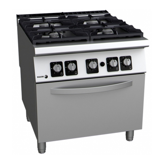
Fagor CG7-20 Allgemeine Bedienungssanleitung Zur Installation Bedienung Und Wartung
Gasherde
Vorschau ausblenden
Andere Handbücher für CG7-20:
- Installations-, gebrauchs- und wartungsanleitung (99 Seiten)
Inhaltsverzeichnis
Verfügbare Sprachen
Verfügbare Sprachen
Quicklinks
Instrucciones generales para la instalación, uso y
Instructions générales pour l'instalation, l'utilisation et l'entretien
General instructions for installation, use and maintenance
Allgemeine bedienungssanleitung zur installation, bedienung und
Instruccioni generali per l´ installazione ,i´uso e la manutenzione
Mod:
CG7-20;
CG7-40;
CG7-41;
CG7-60
CG7-61;
CGB7-61;
CG7-10
CG7-11
CG7-30-D; CG7-30-I;
CG7-31-D; CG7-31-I;
CGE7-41;
mantenimiento
COCINAS A GAS
FOURNEAUX A GAZ
GAS COOKERS
wartung
GAS HERDE
CUCINE A GAS
CG7-20 H;
CG7-20 A
CG7-40 H;
CG7-40 A
CG7-41 H;
CG7-41 A
CG7-60 H
CG7-61 H;
CG7-61 A
CGB7-61 H
CG7-50
CG7-51
CGE7-41 H
U-916501
Inhaltsverzeichnis

Verwandte Anleitungen für Fagor CG7-20


Inhaltszusammenfassung für Fagor CG7-20
- Seite 1 GAS COOKERS Allgemeine bedienungssanleitung zur installation, bedienung und wartung GAS HERDE Instruccioni generali per l´ installazione ,i´uso e la manutenzione CUCINE A GAS Mod: CG7-20; CG7-20 H; CG7-20 A CG7-40; CG7-40 H; CG7-40 A CG7-41; CG7-41 H; CG7-41 A CG7-60 CG7-60 H CG7-61;...
- Seite 2 U026508 CG7-20 G: Entrada de gas G: Gas inlet VM: Grifo-válvula de mesa VM: Table tap-valve CG7-40 G: Entrada de gas G: Gas inlet VM: Grifo-válvula de mesa VM: Table tap-valve CG7-60 G: Gas inlet G: Entrada de gas VM: Table tap-valve...
- Seite 4 CG7-10 G: Entrada de gas G: Gas inlet VM: Grifo-válvula de mesa VM: Table tap-valve CG7-11 CG7-30-D G: Entrada de gas G: Gas inlet VM: Grifo válvula de mesa VM: Table tap-valve...
- Seite 5 CG7-30 I G: Entrada de gas G: Gas inlet VM: Grifo válvula de mesa VM: Table tap-valve CG7-50 G: Gas inlet G: Entrada de gas VM: Table tap-valve VM: Grifo válvula de mesa CG7-31-D...
- Seite 7 Fig 2 Fig 3...
- Seite 39 Nehmen Sie sich einige Minuten Zeit, begeben Sie sich mit diesem Handbuch zum Gerät und „Hand ans Werk”: Die leicht verständlichen Bildinformationen ersetzen die bisher verwendeten Volltextseiten. Allerdings raten wir Ihnen dazu, das vorliegende, von den FAGOR-Küchenchefs verfasste Handbuch gründlich durchzulesen, da Sie nur so in den Genuss der vielfältigen Möglichkeiten und Vorteile dieses Gerätes kommen können.
-
Seite 40: Technische Eigenschaften
Technische Eigenschaften (Tabelle Nr. 1) CG7- CGB7- CG7- CG7- Modell CGE7-41 CG7-20 CG7-40 CG7-41 CG7-61 Breite 1050 1050 1050 AUSSEN- (mm) Tiefe ABMESSUNGEN Höhe Breite OFEN-ABMESSUNGEN (mm) Tiefe Höhe NETTOGEWICHT (kg) 5.000 (Tisch) 7.000 (Tisch) ANZAHL BRENNER 8.000 (Tisch) 7.800 (Ofen) - Seite 41 (Tabelle Nr. 2) CGB7-61 CGE7-41 Modell CG7-20 H CG7-40 H CG7-41 H CG7-60 H CG7-61 H Breite 1050 1050 1050 AUSSEN- (mm) Tiefe ABMESSUNGEN Höhe Breite OFEN-ABMESSUNGEN (mm) Tiefe Höhe NETTOGEWICHT (kg) 5.000 (Tisch) 7.000 (Tisch) ANZAHL BRENNER 8.000 (Tisch) 7.800 (Ofen)
-
Seite 42: Leistungen Der Brenner (Tabelle Nr 4)
UNTERER HEIZWERT 8.573 7.372 8.573 7.372 10.901 11.066 Luftverbrauch (Tabelle Nr. 6) Mod. Für die Verbrennung erforderlicher Luftverbrauch Nm³/h CG7-20; CG7-10 CG7-11;CGF7-31 D/I CG7-20 H CG7-40, CGE7-41 CG7-41 CG7-60 CG7-61 CG7-60 h CG7-41 H CG7-61H Durchmesser der Injektoren und Regulierung (Tabelle Nr 7) -
Seite 43: Kategorien, Gasarten Und Betriebsdrücke (Tabelle Nr 9)
(Tabelle Nr 8) PILOTBRENNER PILOTBRENNER TISCH OFEN FAMILIE/ GAS φInyector φInyector (mm) (mm) (mm) G-110 G-130 G-150 G-20 G-25 1.65 0.40 G-25.1 GZ-35 2.45 G-30 1.10 0.25 G-31 Kategorien, Gasarten und Betriebsdrücke (Tabelle Nr 9) Bestimmungsland Drücke (mbar) Kategorien 20*50 2H3B/P 20/25*28-30/37 BE - FR... -
Seite 44: Positionen Und (Ungefähre) Temperaturen Des Ofens (Tabelle Nr. 10)
Positionen und (ungefähre) Temperaturen des Ofens (Tabelle Nr. 10) GAS OFEN ELETRISCHE OFEN 170-190ºC 160-180ºC 125ºC 90ºC 180-200ºC 180-240ºC 175ºC 120ºC 215ºC 170ºC 250ºC 200ºC 180-200ºC 160-180ºC 265ºC 230ºC 285ºC 260ºC 180-200ºC 160-180ºC 310ºC 280ºC 340ºC 315ºC 160-180ºC 190-210ºC... - Seite 45 1.-INSTALLATION: Aufstellung und Nivellierung Der elektrische Anschluss des Gerätes darf nur von einem AUTORISIERTEN TECHNIKER unter Einhaltung der jeweils geltenden Landesbestimmungen vorgenommen werden. ∗ Die Netzspannung muss mit der auf dem Typenschild angegebenen Spannung übereinstimmen. ∗ Für den Anschluss muss ein Kabelschlauch aus Polychloropren oder einem anderen Werkstoff mit ähnlichen Eigenschaften (H05RN-F) benutzt werden) ∗...
- Seite 46 WICHTIG: Um von der MAXIMAL-Stellung in eine andere Stellung zu wechseln, muss stets der Schalter gedrückt werden. Ausschalten der Tischbrenner a) Wenn Sie sich in den Stellungen MAXIMAL, MINIMAL oder in einer der Zwischenstellungen befinden, muss der Schalter gedrückt, im Uhrzeigersinn in die Stellung PILOTBRENNER gedreht (Abb. 6, Nr. 2) und dann losgelassen werden.
-
Seite 47: Wartung
3.-WARTUNG: Tägliche Reinigung. Um das Gerät stets im optimalen Zustand zu halten, sollten folgende Anweisungen befolgt werden: ∗ Zur Reinigung dürfen weder sandhaltige noch scheuernde Reinigungsmittel verwendet werden. ∗ Zur Reinigung des Gerätes darf kein Druckwasser verwendet werden. ∗ Es wird empfohlen, die Fettauffangschalen täglich zu reinigen. ∗... -
Seite 48: Wichitger Hinweis
WICHITGER HINWEIS: ∗ Der Abluftkamin darf weder ganz noch teilweise verdeckt werden, da sonst die ordnungsgemässe Funktionsweise der Brenner beeinträchtigt wird. ∗ Das Auswechseln von sicherheitsrelevanten Funktionskomponenten darf ausschließlich von einem AUTORISIERTEN FACHTECHNIKER vorgenommen werden. ∗ Beim Auswechseln von Funktionskomponenten muss geprüft werden, dass der Haupthahn für Gas geschlossen ist und sich keine offene Flamme in Gerätenähe befindet.