be cool BC10MBKL2101F Gebrauchsanweisung
Monoblock klimagerät

Verwandte Anleitungen für be cool BC10MBKL2101F


Inhaltszusammenfassung für be cool BC10MBKL2101F
- Seite 1 MONOBLOCK KLIMAGERÄT BC10MBKL2101F AIR CONDITIONER BC10MBKL2101F GEBRAUCHSANWEISUNG OPERATOR'S MANUAL...
-
Seite 2: Erläuterung Der Symbole
ERLÄUTERUNG DER SYMBOLE Warnhinweis, brennbare Materialien. Lesen Sie das Benutzerhandbuch. Bedienungsanleitung. Serviceanzeige, technisches Handbuch lesen. Entsorgung Das Symbol „durchgestrichene Mulltonne" erfordert die separate Entsorgung von Elektro- und Elektronik-Altgeraten (WEEE). Elektrische und elektronische Gerate können gefährliche und umweltgefährdende Stoffe enthalten. Entsorgen Sie dieses daher nicht im unsortierten Restmüll, sondern an einer ausgewiesenen Sammelstelle für Elektro- und Elektronik-Altgeräte. - Seite 3 02 03 WICHTIG! KLIMAGERÄTE MÜSSEN IMMER AUFRECHT GELAGERT UND TRANSPORTIERT WERDEN, DA SONST IRREPARABLE SCHÄDEN AM KOMPRESSOR ENTSTEHEN KÖNNEN. IM ZWEIFELSFALL WIRD EMPFOHLEN, NACH DER INSTALLATION MINDESTENS 24 STUNDEN ZU WARTEN, BEVOR SIE DAS GERÄT IN BETRIEB NEHMEN. • Lesen Sie die Anleitung sorgfältig durch, bevor Sie das Gerät installieren und/oder in Betrieb nehmen.
- Seite 4 • Lassen Sie Kinder nicht unbeaufsichtigt in die Nähe dieses Geräts. • Reinigen Sie das Gerät nicht durch Besprühen oder Eintauchen in Wasser. • Schliessen Sie das Gerät niemals über ein Verlängerungskabel an eine Steckdose an. Wenn keine Steckdose vorhanden ist, sollte eine solche von einer Elektrofachkraft installiert werden.
- Seite 5 04 05 • Vermeiden Sie einen Neustart des Klimageräts, wenn seit dem Ausschalten nicht mindestens 3 Minuten vergangen sind. Dies verhindert Schäden am Kompressor. • Das Gerät sollte nicht in Wasch- oder Feuchträumen installiert werden. • Das Gerät muss in einem Raum ohne Zündquellen (z.
- Seite 6 • Wenn das Gerät in einem unbelüfteten Raum installiert, verwendet oder gelagert wird, muss der Raum so beschaffen sein, dass eine Ansammlung von möglicherweise austretendem Kältemittelgas verhindert wird, da bei Kontakt des Kältemittels mit elektrischen Heizgeräten, Öfen oder anderen Zündquellen Brand- oder Explosionsgefahr besteht. •...
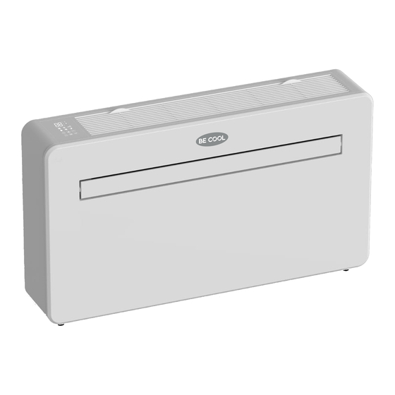
- Seite 7 06 07 PRODUKTÜBERSICHT PRODUKTDIAGRAMM VORNE BEDIENFELD LUFTEINLASS LAMELLEN FRONTBLENDE ZURÜCK WANDHALTERUNGEN HINTERE BLENDE ENTLÜFTUNG ENTLÜFTUNG ABLASSROHR...
-
Seite 8: Was Ist Enthalten
FUNKTIONSMERKMALE • Einfache Bedienung. • Selbstverdunstungsfunktion mit Energiespartechnologie. • Schlankes Design, das sich nahtlos in jeden Einrichtungsstil einfügt. • Heller LED-Bildschirm – zeigt die Temperatur und den aktuellen Modus an. • Ein-/Aus-Timer-Funktion – Sie können wählen, wann das Gerät in Betrieb ist. •... -
Seite 9: Installation
08 09 KUNSTSTOFFLEIT- Fernbedienung WANDHALTERUNG PLATTE, 2 STK. BLECHSCHRAUBE, 2 STK. MONTAGEWINKEL (3,9x10 mm) INSTALLATION ERFORDERLICHE WERKZEUGE WASSERWAAGE BOHRMASCHINE BANDMASS 180 mm KERNBOHRER... - Seite 10 8 mm STEINBOHRER SCHARFES MESSER 20 mm STEINBOHRER STIFT Bevor Sie mit der Installation beginnen, stellen Sie bitte sicher, dass Sie alle erforderlichen Ausrüstungsteile zur Verfügung haben und die Schritte der Installation verstanden haben. Im Zweifelsfall sollte fachkundiger Rat eingeholt werden. Der Installateur muss sicherstellen, dass die geplante Position des Klimageräts geeignet ist und dass keine Kabel und Rohre in der Wand und keine anderen an der Wand befestigten Hindernisse vorhanden sind, die eine Gefahr darstellen und/oder die Fertigstellung der...
- Seite 11 10 11 Das Loch für das Abflussrohr muss mit einem 20-mm-Bohrer gebohrt werden. Achten Sie darauf, dass die Bohrung ein Gefälle von mindestens 5 Grad nach unten aufweist, damit das Wasser richtig abfliessen kann. Verwenden Sie einen 180-mm-Kernbohrer, um die beiden Löcher für die Belüftung des Geräts zu bohren, und achten Sie darauf, dass die beiden Löcher an der Schablone ausgerichtet sind.
- Seite 12 Schneiden Sie das überstehende Entlüftungsrohr mit einem scharfen Messer ab und halten Sie die Kante so sauber wie möglich. Stecken Sie den inneren Befestigungsring der Entlüftungsabdeckung auf die Innenseite der Entlüftung. Falten Sie dann die äussere Lüftungsabdeckung in der Mitte. Befestigen Sie die Ketten an jeder Seite der Lüftungsabdeckung, bevor Sie die Abdeckung durch die Lüftungsöffnung nach...
- Seite 13 12 13 Heben Sie das Gerät an die Wand, richten Sie die Aufhängelöcher mit den Haken an der Aufhängeschiene aus und setzen Sie das Gerät vorsichtig auf Schieben Sie gleichzeitig das Abflussrohr durch das Abflussloch. HINWEIS: 1. Stellen Sie bitte sicher, dass die Rückseite des Geräts fest an der Wand befestigt ist, um unnötige Vibrationen und Geräusche zu vermeiden.
- Seite 14 BETRIEB BEDIENFELD Timertaste Taste Erhöhen/Verringern Ein-/Ausschalten Lüfterdrehzahl Modustaste Angezeigte Symbole Status Digitalanzeige WLAN-Funktion Kindersicherung Kühlfunktion Lüfterfunktion Trocknungsfunktion Heizfunktion Geräuschlosfunktion Drehzahlfunktion...
- Seite 15 14 15 FERNBEDIENUNG Das Klimagerät kann mit der Fernbedienung gesteuert werden. Es sind zwei AAA-Batterien erforderlich (nicht im Lieferumfang). HINWEIS: Weitere Einzelheiten zu den Funktionen finden Sie auf der folgenden Seite. Drücken Sie den Ein-/Ausschalter, Ein-/Ausschalten um das Gerät ein- oder auszuschalten. Drücken Sie die Modustaste, um zwischen den MODUSTASTE Betriebsarten Kühlen, Heizen, Lüfter und Trocknen...
- Seite 16 Die Kühlfunktion ermöglicht es dem Klimagerät, den Raum zu kühlen und gleichzeitig die Luftfeuchtigkeit zu reduzieren. Die gewünschte Temperatur kann mit der Erhöhungs- und Absenkungstaste zwischen 16 °C und 30 °C eingestellt werden. Die Lüfterdrehzahl kann auch über KÜHLUNG die Drehzahltaste eingestellt werden. Im Trocknungsmodus wird der Luft Feuchtigkeit entzogen, die über das installierte Ablaufrohr nach aussen abgeleitet wird.
-
Seite 17: Wlan-Einrichtung Und Smart-Funktionen
16 17 Wird im Kühl- und Heizmodus verwendet, um die gewünschte Temperatur von 16-30 °C einzustellen. Wird auch beim Einstellen des Timers verwendet, um die ERHÖHEN UND Dauer einzustellen. VERRINGERN Nach dem Einschalten des Geräts drücken Sie die Taste «SCHWENKEN», die Lamelle schwenkt kontinuierlich auf und ab;... -
Seite 18: Für Die Einrichtung Verfügbare Verbindungsmethoden
FÜR DIE EINRICHTUNG VERFÜGBARE VERBINDUNGSMETHODEN Das Klimagerät verfügt über zwei verschiedene Einrichtungsmodi, Schnellverbindung und AP-Verbindung (Access Point). Die Schnellverbindung ist eine schnelle und einfache Möglichkeit, das Gerät einzurichten. Die AP-Verbindung nutzt eine direkte lokale WLAN- Verbindung zwischen Ihrem Telefon und dem Klimagerät, um die Netzwerkinformationen hochzuladen. -
Seite 19: Räume Erstellen
18 19 4.Ein Bestätigungscode 5.Geben Sie das Passwort 6.Die App ist jetzt ein, das Sie erstellen wird über die in Schritt 3 registriert. Sie wird Sie möchten. Dieses muss 6- nach der Registrierung ausgewählte Methode 20 Zeichen lang sein und gesendet. -
Seite 20: Verbinden Über Schnellverbindung
EINSTELLEN IHRES STANDORTS WEITEREN RAUM HINZUFÜGEN Bewegen Sie mit dem Finger das Geben Sie den Namen des Raums ein, und orang-efarbene ZUHAUSE-Symbol. drücken Sie oben rechts auf «Fertig». Wenn sich das Symbol an der ungefähren Position Ihres Zuhauses befindet, drücken Sie die Bestätigungstaste in der oberen rechten Ecke. -
Seite 21: Verbindung Über Ap-Modus (Alternative Methode)
20 21 4.Verbinden Sie sich mit einem WLAN und geben Sie das Passwort ein. 5.Klicken Sie auf die Schalt- fläche WEITER, um ein neues Gerät zu scannen und zu verbinden. Warten Sie, bis dieser Vorgang abgeschlos-sen ist. 6.Bitte versuchen Sie es erneut, wenn dies nicht funktioniert. - Seite 22 4) Vergewissern Sie sich, 5) Geben Sie Ihr WLAN- 6) Gehen Sie in die dass die WLAN-Leuchte Passwort ein und drücken Netzwerkeinstellungen am Klimagerät langsam Ihres Telefons und stellen Sie auf Bestätigen. blinkt (einmal alle drei Sie die Verbindung mit Sekunden), und klicken «Smart Life xxx»...
- Seite 23 22 23 STEUERN IHRES GERÄTS ÜBER DIE APP DER STARTBILDSCHIRM Zuhause ändern: Gerät hinzufügen: Wenn Sie mehr als ein Fügen Sie ein neues Zuhause erstellt haben, Gerät in der APP hinzu können Sie zwischen und führen Sie den diesen wechseln. Einrichtungsprozess durch.
- Seite 24 GERÄTEBILDSCHIRM Der Gerätebildschirm ist der Hauptsteuerungsbildschirm für das Klimagerät und bietet Zugriff auf die Bedienelemente zur Änderung der Funktionen und Einstellungen. Zurück: Name bearbeiten: Kehrt zum Startbildschirm Dient zum Ändern zurück. des Namens für das Klimagerät. Aktuelle Raumtemperatur: Zeigt die aktuelle Gewünschte Raumtemperatur an.
- Seite 25 24 25 INTELLIGENTE SZENEN Intelligente Szenen sind ein leistungsfähiges Werkzeug und bieten die Möglichkeit, den Betrieb des Klimageräts sowohl an die Bedingungen innerhalb des Raums als auch an äussere Einflüsse anzupassen. Dies bietet dem Benutzer die Möglichkeit, viel intelligentere Aktionen festzulegen.
- Seite 26 4.Drücken Sie auf den Pfeil neben«Name», 5.Wählen Sie die Funktion aus, stellen Sie den Wert für die Funktion ein und um den Namen für Ihre Szene einzugeben. drücken Sie dann die Pfeiltaste in der Anzeigen auf Startseite: Lassen Sie dies oberen linken Ecke, um zum aktiviert, wenn die Szene als Schaltfläche vorherigen Bildschirm zurückzukehren.
- Seite 27 26 27 AUTOMATION Mit Automation kann eine automatische Aktion für das Gerät eingerichtet werden. Diese kann durch die Uhrzeit, die Innentemperatur, die Luftfeuchtigkeit des Raums, die Wette- rbedingungen und eine Reihe weiterer Einflüsse ausgelöst werden. 1. Drücken Sie auf die 2.
- Seite 28 6. Wählen Sie die Funktion und drücken Sie dann auf die Pfeiltaste, in der linken oberen Ecke, um zum vorherigen Bildschirm zurückzukehren. Auf der Registerkarte «Profil» haben Sie die Möglichkeit, sowohl Ihre Angaben zu bearbeiten als auch die zusätzlichen Funktionen des Geräts zu nutzen. ÄNDERN DES GERÄTENAMENS Wenn Sie sich in einem der Gerätebildschirme befinden, können Sie auf weitere Einstellungen für das Gerät...
-
Seite 29: Fehlerbehebung
28 29 INTEGRATION Dadurch kann das Gerät mit Ihrer bevorzugten Hausautomatisierungs-Hardware wie Google Home und dem Amazon Echo integriert werden. Nach Auswahl von «Weitere Dienste» können Sie Sprachdienste von Drittanbietern integrieren, siehe linkes Bild. FEHLERBEHEBUNG Das Klimagerät darf nicht repariert oder demontiert werden. Eine unsachgemässe Reparatur führt zum Erlöschen der Garantie und kann zu Ausfällen führen, die Verletzungen und Sachschäden verursachen. - Seite 30 Das Klimagerät Das Gerät steht nicht gerade. Prüfen Sie mit einer Wasserwaage, leckt. ob das Gerät waagerecht steht; falls nicht, entfernen Sie es von der Wand und richten Sie es aus. Die Ablaufleitung ist blockiert. Überprüfen Sie die Ablaufleitung, um sicherzustellen, dass sie nicht verstopft oder eingeklemmt ist.
-
Seite 31: Technische Daten
30 31 TECHNISCHE DATEN Modell BC10MBKL2101F 2930W / 2350W Leistung Kühlung / Heizung Aufnahmeleistung Kühlung / 1120W / 745 W Heizung Nennstrom 5.0A Luftstrom 500m³/h EER/COP 2.6/3.1 Sicherung T 15AH, 250V Kompressor Rotary, 290g, R290 gas Schallleistungspegel (LWA) 58dB (A) -
Seite 32: Technische Zeichnung
TECHNISCHE ZEICHNUNG MODELL: BC10MBKL2101F... - Seite 33 32 33 ERSATZTEILLISTE Leitschaufel rechts feste Platte Einbaukasten für Anzeigetafel Befestigungsteil des Luftleitblechs Anzeige-Leuchtfeld Windabweiser Paneelspiegel Vordere Abdeckung Filter Vordere Abdeckung Verdampfer-Baugruppe Linker Deckel Wasserschalen Abdeckung für elektronisches Lüfterräder für Luftzufuhr Steuergehäuse Elektrischer Schaltkasten aus Rotor-Wellenschutzhülse Kunststoff Antriebsplatte mit variabler Frequenz Auslaufschutz Haupt-Bedienfeld Schaumteil für Luftkanal...
- Seite 34 ERSATZTEILLISTE Baugruppe Wasserablassschalter Abluft-Windrad Unterwasserschalen Motorfuss (DC) Basis Unterer Luftkanal 1 Kunststoffversiegelter bürstenloser Stützstange Gleichstrommotor Hintere Abdeckplatte Motorhalterung Elektronische Hintere Blende Expansionsventildüsen 1 Hinterer Schutzfilter Vierwegeventil-Anschluss 2 Abdeckung rechts/links Vierwegeventil-Anschluss 1 Rechte Verbindungsleiste Verflüssiger-Baugruppe Leuchten-Halteplatte Kompressor-Druckleitung Ablaufrohr Vierwegeventil Gehäusestützen Vierwegeventil-Spule Gummifüsse Kompressor-Saugleitung Wassermanagement-Karte...
- Seite 35 34 35...
- Seite 69 68 69...
- Seite 70 NOTE...
- Seite 71 70 71 NOTE...
- Seite 72 Schuss Home Electronic GmbH Scheringgasse 3, A-1140 Wien Tel: +43 (1) 97 0 21 – 0...