ABB CC-U/STD Betriebsanleitung
Universalsignalwandler für standardsignale
Inhaltsverzeichnis
Quicklinks
CC-U/STD
(D)
Betriebs- und Montageanleitung
Universalsignalwandler für Standardsignale,
CC Reihe
Hinweis: Diese Betriebs- und Montageanleitung enthält
nicht sämtliche Detailinformationen zu allen Typen der
Produktreihe und kann auch nicht jeden Einsatzfall der
Produkte berücksichtigen. Alle Angaben dienen aus-
schließlich der Produktbeschreibung und sind nicht als
zugesicherte Eigenschaften im Rechtssinne aufzufassen.
Weiterführende Informationen und Daten erhalten Sie in
den Katalogen und Datenblättern der Produkte, über die
örtliche ABB-Niederlassung sowie auf der ABB Home-
page unter http://www.abb.com. Technische Änderungen
jederzeit vorbehalten. In Zweifelsfällen gilt der deutsche
Text.
Nur von einer entsprechend qualifizierten Fachkraft
zu installieren. Dabei landesspezifische Vorschriften
(z.B. VDE, etc.) beachten. Vor der Installation diese
Betriebs- und Montageanleitung sorgfältig lesen
und beachten. Die Geräte sind wartungsfreie
Einbaugeräte.
(GB) Operating and installation instructions
Universal converter for standard signals,
CC range
Note: These operating and installation instructions
cannot claim to contain all detailed information of all
types of this product range and can even not consider
every possible application of the products. All statements
serve exclusively to describe the product and have not to
be understood as assured characteristics with legal
force. Further information and data is obtainable from the
catalogues and datasheets of this product, from the local
ABB sales organisations as well as on the ABB
homepage http://www.abb.com. Subject to change
without prior notice. The German text applies in cases of
doubt.
The device must be installed by qualified persons
only and in accordance with the specific national
regulations (e.g., VDE, etc.). Before installing this
unit, read these operating and installation
instructions carefully and completely. The devices
are maintenance-free chassis-mounted units.
ABB Stotz-Kontakt GmbH
Hauptstr. 14-16
78132 Hornberg / Germany
www.abb.com/lowvoltage -> Control Products -> Electronic Relays
(F)
Instructions de service et de montage
Convertisseur universel pour signaux standards,
gamme CC
Note: Ces instructions de service et de montage ne
contiennent pas toutes les informations relatives à tous
les types de cette gamme de produits et ne peuvent pas
non plus tenir compte de tous les cas d'application.
Toutes les indications ne sont données qu'à titre de
description du produit et ne constituent aucunes
obligations légales. Pour de plus amples informations,
veuillez-vous référer aux cataloges et aux fiches
techniques des produits, à votre agence ABB ou à notre
site http://www.abb.com. Sous réserve de modifications
techniques. En cas de divergences, le texte allemand
fait foi.
L'installation de ces produits doit être réalisée
uniquement par une personne compétente et en
conformité avec les prescriptions nationales
(p.e. VDE, etc.). Avant l'installation de cet appareil
veuillez lire l'intégralité de ces instructions.
Ces produits sont des appareils encliquetables
qui ne nécessitent pas d'entretien.
(E)
Instrucciones de servicio y de montaje
Convertidor universal para señales estándard,
serie CC
Nota: Estas instrucciones no contienen todas las
informaciones detalladas relativas a todos los tipos del
producto ni pueden considerar todos los casos de
operación. Todas las indicaciones son a título descriptivo
del producto y no constituyen obligaciones legales.
Para más información, consulte los catálogos, las hojas
de características, la sucursal local de ABB o la Web
http://www.abb.com. Sujeto a cambios técnicos sin
previo aviso. En caso de duda, prevalece el texto
alemán.
La instalación debe llevarse a cabo sólo por
personal especializado. Es necesario respetar las
normas especificas del país (p.ej. VDE, etc.).
Antes de la instalación lea completamente estas
instrucciones. Estos aparatos son equipos para
su montaje en conjuntos y son de libre
mantenimiento.
Inhaltsverzeichnis

Verwandte Anleitungen für ABB CC-U/STD


Inhaltszusammenfassung für ABB CC-U/STD
- Seite 1 Katalogen und Datenblättern der Produkte, über die veuillez-vous référer aux cataloges et aux fiches örtliche ABB-Niederlassung sowie auf der ABB Home- techniques des produits, à votre agence ABB ou à notre page unter http://www.abb.com. Technische Änderungen site http://www.abb.com. Sous réserve de modifications jederzeit vorbehalten.
- Seite 2 в качестве гарантированных характеристик, prodotti, o la nostra homepage http://www.abb.com/, имеющих юридическую силу. Дополнительную oppure rivolgersi alla locale filiale ABB. Ci riserviamo di информацию и данные можно получить из ката eventuali modifiche tecniche. In caso di differenze o логов и Листов данных на настоящее изделие...
-
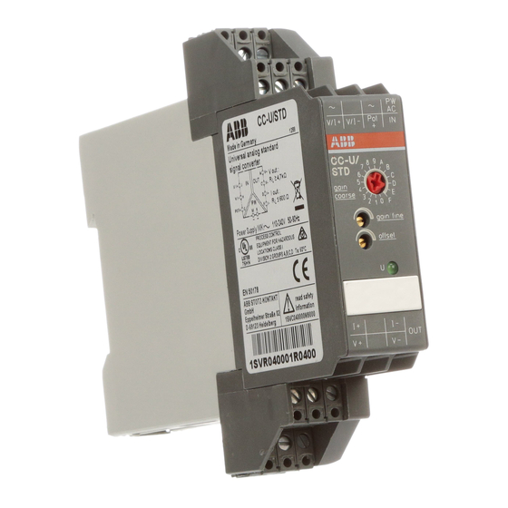
Seite 3: Frontansicht Mit Bedienelementen
Frontansicht mit Bedienelementen Deutsch 8 seitliche DIP-Schalter, SW 1.1 ... 1.8, zur Eingangs- M L K konfiguration Mit den 8 seitlichen Schaltern können 16 Standard- Eingangssignale nach Tabelle 1a sowie weitere 12 nicht standardisierte Signale durch Schalterkombinationen nach Tabelle 1b konfiguriert werden. Umschaltung zwischen Spannung u. -
Seite 4: Electrical Connection
Face avant et dispositifs de Front view with operating controls English Français commande 8 micro-interrupteurs latéraux, SW 1.1 ... 1.8, pour la 8 lateral DIP switches, SW 1.1 ... 1.8, for input configuration de l’entrée configuration With the 8 lateral switches it is possible to configure 16 Avec ces 8 interrupteurs, il est possible de configurer 16 signaux standards d’entrée (voir tableau 1a), de même standard input signals as shown in table 1a, as well as... -
Seite 5: Conexión Eléctrica
Español Italiano Vista frontal con elementos de Vista frontale con gli elementi di mando comando 8 interruptores DIP laterales, SW 1.1 ... 1.8, para la 8 DIP switch laterali, SW 1.1 ... 1.8, per la configuración de la entrada configurazione degli ingressi Con estos 8 interruptores es posible configurar 16 Con questi 8 interruttori è... - Seite 6 Русский Русский Вид спереди на элементы управления 8 боковых DIP переключателей, SW 1.1 ... 1.8, для конфигурирования входных сигналов При помощи 8 боковых переключателей можно сконфигурировать 16 стандартных входных сигналов как указано в табл. 1a и 12 нестандарт ных входных сигналов как указано в табл. 1b. Выбор...
- Seite 7 Tab. 2 Output Tab. 1 Input Gain coarse a) standard typ. a) standard 0 ... 5 V Potentiometer A ... D 0 ... 10 V 0 ... 50 mV A ... D 1 ... 5 V 0 ... 100 mV 4 ...
-
Seite 8: Additional Information
ADDITIONAL INFORMATION Standard 1604 and CSA 22.2 No. 213-M1987. This equipment is suitable for use in Class I, Division 2, Groups A, B, C, and D or non-hazardous locations only. WARNING - EXPLOSION HAZARD - Substitution of components may impair suitability for Class I, Division 2. - Seite 9 Potentiometereingang: Es können Potentiometer mit einem Widerstand von 470 Ohm bis 1 MOhm angeschlossen werden. Je nach DIP-Schalterkonfiguration besitzt der CC-U/STD 2 synchron arbeitende Ausgänge: Einen Spannungs- und einen Stromausgang. Einer dieser Ausgänge kann mit den frontseitigen Potentio- metern abgeglichen werden.
-
Seite 10: Adjustment Procedure
470 Ohm à 1 MOhm. Selon la configuration des micro-interrupteurs, le Depending on the configuration of the DIP switches, the CC-U/STD possède 2 sorties travaillant de manière CC-U/STD provides 2 synchronously working outputs: One output for voltage and one for current. -
Seite 11: Procedura Di Regolazione
470 Ohm fino a 1 MOhm. Dependiendo de la configuración de los interruptores DIP, A seconda della configurazione dei DIP switch, il el CC-U/STD dispone de 2 salidas trabajando sincróni- CC-U/STD disporrà di 2 uscite sincronizzate: camente: Un’uscita in tensione ed un’altra in corrente. - Seite 12 III Регулировка Русский 1. Выберите требуемый входной и выходной сигнал, а также установите необходимую конфигурацию для требуемой реакции прибора на прерывания входного сигнала (см. табл. 1 и 2) 2. Установите смещение: Подайте самый слабый сигнал или сигнал, близ кий к 0 на клеммы J и H. Установите смещение при...