Herunterladen Inhalt Inhalt Diese Seite drucken
Inhaltsverzeichnis

Werbung

Verfügbare Sprachen

Verfügbare Sprachen

All manuals and user guides at all-guides.com
Quick Start
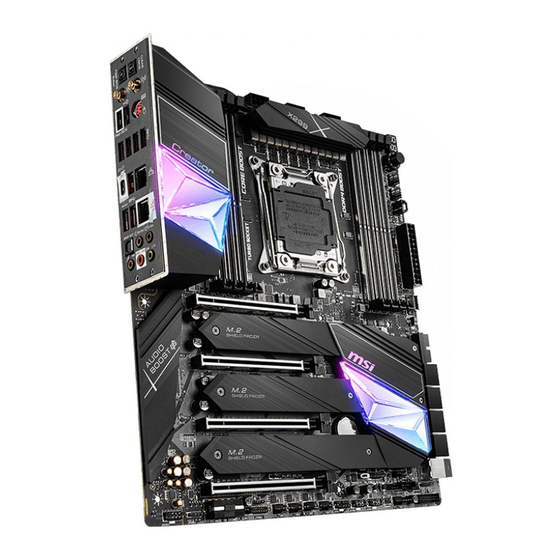
Thank you for purchasing the MSI
Creator X299
motherboard. This
®
Quick Start section provides demonstration diagrams about how to
install your computer. Some of the installations also provide video
demonstrations. Please link to the URL to watch it with the web
browser on your phone or tablet. You may have even link to the URL
by scanning the QR code.
Kurzanleitung
Danke, dass Sie das MSI
Creator X299
Motherboard gewählt
®
haben. Dieser Abschnitt der Kurzanleitung bietet eine Demo zur
Installation Ihres Computers. Manche Installationen bieten auch
die Videodemonstrationen. Klicken Sie auf die URL, um diese
Videoanleitung mit Ihrem Browser auf Ihrem Handy oder Table
anzusehen. Oder scannen Sie auch den QR Code mit Ihrem Handy,
um die URL zu öffnen.
Présentation rapide
Merci d'avoir choisi la carte mère MSI
Creator
X299. Ce manuel
®
fournit une rapide présentation avec des illustrations explicatives
qui vous aideront à assembler votre ordinateur. Des tutoriels vidéo
sont disponibles pour certaines étapes. Cliquez sur le lien fourni
pour regarder la vidéo sur votre téléphone ou votre tablette. Vous
pouvez également accéder au lien en scannant le QR code qui lui est
associé.
Быстрый старт
Благодарим вас за покупку материнской платы MSI
Creator
X299.
®
В этом разделе представлена информация, которая поможет вам
при сборке комьютера. Для некоторых этапов сборки имеются
видеоинструкции. Для просмотра видео, необходимо открыть
соответствующую ссылку в веб-браузере на вашем телефоне или
планшете. Вы также можете выполнить переход по ссылке, путем
сканирования QR-кода.
I
Quick Start

Werbung

Inhaltsverzeichnis
loading

Inhaltszusammenfassung für MSI Creator X299

  • Seite 1 Videoanleitung mit Ihrem Browser auf Ihrem Handy oder Table anzusehen. Oder scannen Sie auch den QR Code mit Ihrem Handy, um die URL zu öffnen. Présentation rapide Merci d’avoir choisi la carte mère MSI Creator X299. Ce manuel ® fournit une rapide présentation avec des illustrations explicatives qui vous aideront à...
  • Seite 2 All manuals and user guides at all-guides.com Installing a Processor/ Installation des Prozessors/ Installer un processeur/ Установка процессора https://youtu.be/ecdkLMmkya4 Quick Start...
  • Seite 3 All manuals and user guides at all-guides.com Installing DDR4 memory/ Installation des DDR4-Speichers/ Installer une mémoire DDR4/ Установка памяти DDR4 http://youtu.be/T03aDrJPyQs 1 DIMM Intel® Core™ X-series 2 DIMMs 10000/ 9000/ 78xx (above) 4 DIMMs processors 8 DIMMs Quick Start...
  • Seite 4 All manuals and user guides at all-guides.com Connecting the Front Panel Header/ Anschließen der Frontpanel-Stiftleiste/ Connecter un connecteur du panneau avant/ Подключение разъемов передней панели http://youtu.be/DPELIdVNZUI Power LED Power Switch JFP1 Reserved HDD LED Reset Switch HDD LED + Power LED + HDD LED - Power LED - Reset Switch...
  • Seite 5 All manuals and user guides at all-guides.com Installing the Motherboard/ Installation des Motherboards/ Installer la carte mère/ Установка материнской платы BAT1 Quick Start...
  • Seite 6 All manuals and user guides at all-guides.com Connecting the Power Connectors/ Stromanschlüsse anschliessen/ Connecter les câbles du module d’alimentation/ Подключение разъемов питания http://youtu.be/gkDYyR_83I4 ATX_PWR1 CPU_PWR1 CPU_PWR2 PCIE_PWR1 CPU_PWR3 Quick Start...
  • Seite 7 All manuals and user guides at all-guides.com Installing SATA Drives/ Installation der SATA-Laufwerke/ Installer le disque dur SATA/ Установка дисков SATA http://youtu.be/RZsMpqxythc Quick Start...
  • Seite 8 All manuals and user guides at all-guides.com Installing a Graphics Card/ Einbau der Grafikkarte/ Installer une carte graphique/ Установка дискретной видеокарты http://youtu.be/mG0GZpr9w_A VIII Quick Start...
  • Seite 9 All manuals and user guides at all-guides.com Connecting Peripheral Devices/ Peripheriegeräte/ Connecter un périphérique anschliessen/ Подключение периферийных устройств Quick Start...
  • Seite 10: Power On/ Einschalten/ Mettre Sous-Tension/ Включение Питания

    All manuals and user guides at all-guides.com Power On/ Einschalten/ Mettre sous-tension/ Включение питания Quick Start...
  • Seite 11: Inhaltsverzeichnis

    All manuals and user guides at all-guides.com Contents Safety Information ....................3 Specifications ......................4 JCORSAIR1 Connector Specification ..............10 Package contents ....................10 Rear I/O Panel ..................... 11 LAN Port LED Status Table .................. 11 Audio Ports Configuration ..................11 Realtek Audio Console ..................
  • Seite 12 All manuals and user guides at all-guides.com POWER1, RESET1: Power Button, Reset Button ..........36 JTBT1: Thunderbolt Add-on Card Connector ............36 BIOS_SW1: Multi-BIOS Switch ................37 JRGB1: RGB LED connector ................. 38 JRAINBOW1~2: Addressable RGB LED connectors ..........39 JCORSAIR1: CORSAIR Connector ................
  • Seite 13: Safety Information

    All manuals and user guides at all-guides.com Safety Information ∙ The components included in this package are prone to damage from electrostatic discharge (ESD). Please adhere to the following instructions to ensure successful computer assembly. ∙ Ensure that all components are securely connected. Loose connections may cause the computer to not recognize a component or fail to start.
  • Seite 14: Specifications

    ∙ Supports non-ECC UDIMM memory ∙ Supports Intel® Extreme Memory Profile (XMP) * Please refer www.msi.com for more information on compatible memory. ∙ 4x PCIe 3.0 x16 slots ▪ Support x8/ x8/ x16/ x8 and x16/ x0/ x16/ x8 modes with the 48-lane CPU.
  • Seite 15 All manuals and user guides at all-guides.com Continued from previous page Realtek ALC1220 Codec ® Audio ∙ 7.1-Channel High Definition Audio ∙ Supports Optical S/PDIF output Intel® X299 Chipset ∙ 8x SATA 6Gb/s ports ∙ 1x M.2 slot (M2_1, Key M)* ▪...
  • Seite 16: Internal Connectors

    All manuals and user guides at all-guides.com Continued from previous page ∙ 1x 24-pin ATX main power connector ∙ 3x 8-pin ATX 12V power connectors ∙ 1x flat 4-pin ATX 12V power connector (Provides additional power for PCIe x16 slots) ∙...
  • Seite 17 ∙ Drivers ∙ CREATOR CENTER ∙ Nahimic Audio ∙ CPU-Z MSI GAMING Software ∙ MSI App Player (BlueStacks) ∙ Open Broadcaster Software (OBS) ∙ Google Chrome™ ,Google Toolbar, Google Drive ∙ Norton™ Internet Security Solution Continued on next page Specifications...
  • Seite 18 ∙ Creator Hotkey ∙ Mystic Light ∙ Hardware Monitor Creator Center ∙ True Color Features ∙ Live update Please refer to http://download.msi. ∙ Speed Up com/manual/mb/CREATORCENTER. pdf for more details. ∙ Smart Tool ∙ Super Charger ∙ Audio ▪ Audio Boost 4 ▪...
  • Seite 19 All manuals and user guides at all-guides.com Continued from previous page ∙ Protection ▪ DDR4 Steel Armor ▪ M.2 Shield Frozr ▪ PCI-E Steel Armor ▪ Pre-installed IO shielding ∙ Performance ▪ Multi GPU-SLI Technology ▪ Multi GPU-CrossFire Technology ▪ DDR4 Boost ▪...
  • Seite 20: Jcorsair1 Connector Specification

    HD120 RGB Fan SP120 RGB Fan LL120 RGB Fan Package contents Please check the contents of your motherboard package. It should contain: Motherboard Creator X299 User manual Documentation Quick installation guide Application USB drive with drivers & utilities SATA 6Gb/s cable...
  • Seite 21: Rear I/O Panel

    All manuals and user guides at all-guides.com Rear I/O Panel Wi-Fi Antenna 1Gbps LAN Audio Ports connectors 10 Gbps PS/2 Combo port Clear CMOS button Flash BIOS Button USB 3.2 Optical S/PDIF-Out Gen 2x2 USB 3.2 Gen 1 USB 2.0 Type-A Type-C Type-A USB 3.2 Gen 1...
  • Seite 22: Realtek Audio Console

    All manuals and user guides at all-guides.com Realtek Audio Console After Realtek Audio Console is installed. You can use it to change sound settings to get better sound experience. Application Enhancement Device Selection Main Volume Connector Settings Jack Status ∙ Device Selection - allows you to select a audio output source to change the related options.
  • Seite 23 All manuals and user guides at all-guides.com Audio jacks to headphone and microphone diagram Audio jacks to stereo speakers diagram AUDIO INPUT Audio jacks to 7.1-channel speakers diagram AUDIO INPUT Rear Front Side Center/ Subwoofer Rear I/O Panel...
  • Seite 24: Installing Antennas

    All manuals and user guides at all-guides.com Installing Antennas 1. Combine the antenna with the base. 2. Screw two antenna cables tight to the WiFi antenna connectors as shown. 3. Place the antenna as high as possible. Rear I/O Panel...
  • Seite 25: Overview Of Components

    All manuals and user guides at all-guides.com Overview of Components CPU Socket DIMMA2 DIMMD1 CPU_PWR3 DIMMA1 DIMMD2 DIMMB2 DIMMC1 DIMMB1 DIMMC2 CPU_PWR2 CPU_FAN1 CPU_PWR1 PUMP_FAN1 SYS_FAN4 JCORSAIR1 JRAINBOW1 ATX_PWR1 SYS_FAN1 VRAID1 JUSB5 PCI_E1 JUSB4 M2_1 PCI_E2 SATA▼1▲2 M2_2 SATA▼3▲4 SATA▼5▲6 PCI_E3 M2_3 BAT1...
  • Seite 26: Cpu Socket

    Always unplug the power cord from the power outlet before installing or removing ∙ the CPU. Please retain the CPU protective cap after installing the processor. MSI will deal ∙ with Return Merchandise Authorization (RMA) requests if only the motherboard comes with the protective cap on the CPU socket.
  • Seite 27: Dimm Slots

    All manuals and user guides at all-guides.com DIMM Slots B1B2A1A2 C2C1D2D1 Memory module installation recommendation 1 DIMM BAT1 2 DIMMs 3 DIMMs Intel® Core™ X-series 4 DIMMs 10000/ 9000/ 78xx (above) 5 DIMMs processors 6 DIMMs 7 DIMMs 8 DIMMs DIMMB1 DIMMB1 DIMMB2...
  • Seite 28 It is recommended to use a more efficient memory cooling system for full DIMMs ∙ installation or overclocking. The stability and compatibility of installed memory modules depend on installed ∙ CPU and devices when overclocking. Please refer www.msi.com for more information on compatible memory. ∙ Overview of Components...
  • Seite 29: Pci_E1~4: Pcie Expansion Slots

    All manuals and user guides at all-guides.com PCI_E1~4: PCIe Expansion Slots PCI_E1: PCIe 3.0 x16 (CPU lanes) PCI_E2: PCIe 3.0 x8 (CPU lanes) PCI_E3: PCIe 3.0 x16 (CPU lanes) BAT1 PCI_E4: PCIe 3.0 x8 (CPU lanes) PCIe, M2_2 and M2_3 slots bandwidth table for 48-lane CPU Graphics Card 2-Way...
  • Seite 30: Vraid1: Virtual Raid On Cpu Connector

    ∙ The PCI_E4 slot and M2_3 slot are unavailable with 28-lane CPU. If you install a large and heavy graphics card, you need to use a tool such as MSI ∙ Gaming Series Graphics Card Bolster to support its weight to prevent deformation of the slot.
  • Seite 31: U2_1: U.2 Connector

    All manuals and user guides at all-guides.com U2_1: U.2 Connector This connector is a U.2 interface port. Each connector can connect to one PCIe 3.0 x4 NVMe storage device. ⚽ Video Demonstration Watch the video to learn how to Install U.2 SSD.
  • Seite 32: M2_1~3: M.2 Slots (Key M)

    All manuals and user guides at all-guides.com M2_1~3: M.2 Slots (Key M) ⚠ Important Intel RST only supports PCIe M.2 SSD with UEFI ROM. ∙ ® ∙ Intel Optane™ Memory Ready for M2_1 slot. ® M2_2 & M2_3 slots only support PCIe 3.0 interface. ∙...
  • Seite 33 All manuals and user guides at all-guides.com 3. For 2242/ 2260 M.2 SSD, please move and fasten the M.2 standoff to the appropriate position to your M.2 SSD. For 2280 M.2 SSD, please skip this step. For 22110 M.2 SSD, please remove the M.2 standoff. 4.
  • Seite 34 All manuals and user guides at all-guides.com Installing M.2 XPANDER-AERO card To install the M.2 XPANDER-AERO card, please follows the steps below. 1. Remove the heatsink by loosening four screws on the back of the M.2 XPANDER- AERO card. 2. Loosen M.2 screw from M.2 standoff. 3.
  • Seite 35 All manuals and user guides at all-guides.com 9. Insert the M.2 XPANDER-AERO card into the PCI_E1 or PCI_E3 slot. 10. Use the screw to secure the M.2 XPANDER-AERO card. PCI_E1/ PCI_E3 11. Connect the PCIE_PWR1 to the power supply. 12. Connect the case’s HDD LED cable to the JCASE connector. 13.
  • Seite 36: Sata1~8: Sata 6Gb/S Connectors

    All manuals and user guides at all-guides.com SATA1~8: SATA 6Gb/s Connectors These connectors are SATA 6Gb/s interface ports. Each connector can connect to one SATA device. SATA2 SATA1 SATA4 SATA3 SATA6 SATA5 SATA8 SATA7 ⚠ Important ∙ Please do not fold the SATA cable at a 90-degree angle. Data loss may result during transmission otherwise.
  • Seite 37: Cpu_Pwr1~3, Atx_Pwr1, Pcie_Pwr1: Power Connectors

    All manuals and user guides at all-guides.com CPU_PWR1~3, ATX_PWR1, PCIE_PWR1: Power Connectors These connectors allow you to connect an ATX power supply. CPU_PWR1~3 Ground +12V Ground +12V Ground +12V Ground +12V +3.3V +3.3V +3.3V -12V Ground Ground PS-ON# Ground Ground Ground ATX_PWR1 Ground...
  • Seite 38: Oc1: Oc Genie 4 Knob

    ∙ dual fan radiator for better cooling and performance. ∙ You can also control the OC GENIE 4 function in BIOS Setup or with MSI CREATOR CENTER software. ∙ In order to optimize performance and improve system stability, when you activate the OC GENIE 4 function, please leave the settings in the BIOS >...
  • Seite 39 All manuals and user guides at all-guides.com OC GENIE 4 Knob overclocking stage table CPU Max Frequency Stage i7-7800X i7-7820X i9-7900X i9-7920X i9-7940X i9-7960X 3.5 GHz 3.6 GHz 3.3 GHz 2.9 GHz 3.1 GHz 2.8 GHz 4.1 GHz 4.4 GHz 4.4 GHz 4.4 GHz 4.4 GHz...
  • Seite 40: Oc_Rt1: Oc Retry Jumper

    All manuals and user guides at all-guides.com OC_RT1: OC Retry Jumper When you short this jumper, the system will keep retrying OC items until it boot up successfully. OC_FS1: OC Force Enter BIOS Jumper When you short this jumper, the system will be forced access to the BIOS and skip OC failure messages .
  • Seite 41 All manuals and user guides at all-guides.com CPU_FAN1, PUMP_FAN1, SYS_FAN1~4, EXS_FAN1~2: Fan Connectors Fan connectors can be classified as PWM (Pulse Width Modulation) Mode or DC Mode. PWM Mode fan connectors provide constant 12V output and adjust fan speed with speed control signal.
  • Seite 42: W_Flow1: Water Flow Meter Connector

    All manuals and user guides at all-guides.com W_FLOW1: Water Flow Meter Connector This connector allows you to connect a water flow meter to monitor the flow rate of your liquid cooling system. Ground WFLOW IN WFLOW PWR T_SEN1: Thermal Sensor Connector This connector allows you to connect the theral sensor cable and use it to monitor the temperature of the detection point.
  • Seite 43: Jusb5: Usb 3.2 Gen 2 Type-C Connector

    All manuals and user guides at all-guides.com JUSB5: USB 3.2 Gen 2 Type-C Connector This connector allows you to connect USB 3.2 Gen 2 Type-C connector on the front panel. The connector possesses a foolproof design. When you connect the cable, be sure to connect it with the corresponding orientation.
  • Seite 44: Jusb1~2: Usb 2.0 Connectors

    All manuals and user guides at all-guides.com JUSB1~2: USB 2.0 Connectors These connectors allow you to connect USB 2.0 ports on the front panel. USB0- USB1- USB0+ USB1+ Ground Ground No Pin ⚠ Important Note that the VCC and Ground pins must be connected correctly to avoid possible ∙...
  • Seite 45: Jaud1: Front Audio Connector

    All manuals and user guides at all-guides.com JAUD1: Front Audio Connector This connector allows you to connect audio jacks on the front panel. MIC L Ground MIC R Head Phone R MIC Detection SENSE_SEND No Pin Head Phone L Head Phone Detection JCI1: Chassis Intrusion Connector This connector allows you to connect the chassis intrusion switch cable.
  • Seite 46: Jbat1: Clear Cmos (Reset Bios) Jumper

    All manuals and user guides at all-guides.com JBAT1: Clear CMOS (Reset BIOS) Jumper There is CMOS memory onboard that is external powered from a battery located on the motherboard to save system configuration data. If you want to clear the system configuration, set the jumpers to clear the CMOS memory.
  • Seite 47: Bios_Sw1: Multi-Bios Switch

    When BIOS updating fails or causes the computer non-bootable, you can recover the failed BIOS by the steps below. Before recovering, please download the latest BIOS file that matches your motherboard model from MSI website. And then save the BIOS file to the root of the USB flash drive.
  • Seite 48: Jrgb1: Rgb Led Connector

    (12V/G/R/B) with the maximum power rating of 3A (12V). Always turn off the power supply and unplug the power cord from the power outlet ∙ before installing or removing the RGB LED strip. Please use MSI’s software to control the extended LED strip. ∙ Overview of Components...
  • Seite 49: Jrainbow1~2: Addressable Rgb Led Connectors

    (5V). In the case of 20% brightness, the connector supports up to 200 LEDs. ∙ Always turn off the power supply and unplug the power cord from the power outlet before installing or removing the RGB LED strip. ∙ Please use MSI’s software to control the extended LED strip. Overview of Components...
  • Seite 50: Jcorsair1: Corsair Connector

    The JCORSAIR1 connector allows you to connect the CORSAIR Individually Addressable Lighting PRO RGB LED strips 5V or CORSAIR RGB fans with the CORSAIR fan hub. Once all items are connected properly, you can control the CORSAIR RGB LED strips and fans with MSI's software. Data Ground...
  • Seite 51: Onboard Leds

    All manuals and user guides at all-guides.com Onboard LEDs EZ Debug LED These LEDs indicate the debug status of the motherboard. CPU - indicates CPU is not detected or fail. DRAM - indicates DRAM is not detected or fail. VGA - indicates GPU is not detected or fail. BOOT - indicates the booting device is not detected or fail.
  • Seite 52: Multi-Bios Leds

    All manuals and user guides at all-guides.com Multi-BIOS LEDs Multi-BIOS LEDs indicate which BIOS ROM is in operation. Red : BIOS A White : BIOS B Debug Code LED The Debug Code LED displays progress and error codes during and after POST. Refer to the Debug Code LED table for details.
  • Seite 53: Debug Code Led Table

    All manuals and user guides at all-guides.com Debug Code LED Table SEC Progress Codes Power on. Reset type detection (soft/hard) AP initialization before microcode loading System Agent initialization before microcode loading PCH initialization before microcode loading Microcode loading AP initialization after microcode loading System Agent initialization after microcode loading PCH initialization after microcode loading Cache initialization...
  • Seite 54 All manuals and user guides at all-guides.com Memory initialization error. Invalid memory type or incompatible memory speed Memory initialization error. SPD reading has failed Memory initialization error. Invalid memory size or memory modules do not match Memory initialization error. No usable memory detected Unspecified memory initialization error Memory not installed Invalid CPU type or Speed...
  • Seite 55 All manuals and user guides at all-guides.com USB Detect USB Enable 9E -9F Reserved for future AMI codes IDE initialization is started IDE Reset IDE Detect IDE Enable SCSI initialization is started SCSI Reset SCSI Detect SCSI Enable Setup Verifying Password Start of Setup Setup Input Wait Ready To Boot event...
  • Seite 56: Cpu Temperature

    All manuals and user guides at all-guides.com S3 Resume is stared (S3 Resume PPI is called by the DXE IPL) S3 Boot Script execution Video repost OS S3 wake vector call E4 - E7 Reserved for future AMI progress codes S3 Resume Error Codes S3 Resume Failed S3 Resume PPI not Found...
  • Seite 57: Installing Os, Drivers & Utilities

    All manuals and user guides at all-guides.com Installing OS, Drivers & Utilities Please download and update the latest utilities and drivers at www.msi.com Installing Windows ® 1. Power on the computer. 2. Insert the Windows 10 installation disc/USB into your computer.
  • Seite 58: Bios Setup

    All manuals and user guides at all-guides.com BIOS Setup The default settings offer the optimal performance for system stability in normal conditions. You should always keep the default settings to avoid possible system damage or failure booting unless you are familiar with BIOS. ⚠...
  • Seite 59: Resetting Bios

    Updating BIOS Updating BIOS with M-FLASH Before updating: Please download the latest BIOS file that matches your motherboard model from MSI website. And then save the BIOS file into the USB flash drive. Updating BIOS: 1. Insert the USB flash drive that contains the update file into the USB port.
  • Seite 60 1. Please download the latest BIOS file that matches your motherboard model from the MSI® website. 2. Rename the BIOS file to MSI.ROM, and save it to the root of your USB flash drive (FAT32 format). 3. Connect the power supply to CPU_PWR1 and ATX_PWR1. (No need to install CPU and memory.)
  • Seite 61: Ez Mode

    All manuals and user guides at all-guides.com EZ Mode At EZ mode, it provides the basic system information and allows you to configure the basic setting. To configure the advanced BIOS settings, please enter the Advanced Mode by pressing the Setup Mode switch or F7 function key. Screenshot XMP switch Setup Mode switch...
  • Seite 62 All manuals and user guides at all-guides.com ∙ System information - shows the CPU/ DDR speed, CPU/ MB temperature, MB/ CPU type, memory size, CPU/ DDR voltage, BIOS version and build date. ∙ Boot device priority bar - you can move the device icons to change the boot priority. The boot priority from high to low is left to right.
  • Seite 63: Advanced Mode

    All manuals and user guides at all-guides.com Advanced Mode Press Setup Mode switch or F7 function key can switch between EZ Mode and Advanced Mode in BIOS setup. XMP switch Setup Mode switch Screenshot Search Language System information Boot device OC GENIE 4 priority bar switch...
  • Seite 64: Oc Menu

    All manuals and user guides at all-guides.com OC Menu This menu is for advanced users who want to overclock the motherboard. ⚠ Important Overclocking your PC manually is only recommended for advanced users. ∙ ∙ Overclocking is not guaranteed, and if done improperly, it could void your warranty or severely damage your hardware.
  • Seite 65 All manuals and user guides at all-guides.com ▶ CPU Ratio [Auto] Sets the CPU ratio that is used to determine CPU clock speed. This item can only be changed if the processor supports this function. ▶ Numbers of CPU Cores of Group X [Auto] * Sets the numbers of CPU cores as a group for running target CPU Turbo Ratio.
  • Seite 66 All manuals and user guides at all-guides.com ▶ Enhanced Turbo [Auto]* Enables or disables Enhanced Turbo function for all CPU cores to boost CPU performance. This item appears when the installed CPU supports this function. [Auto] This setting will be configured automatically by BIOS. [Enabled] All CPU cores would be increased to maximum turbo ratio.
  • Seite 67 All manuals and user guides at all-guides.com ▶ Dynamic Frequency Search Mode [Once] Sets the search mode of the dynamic BCLK. This item will be available when the Dynamic Frequency Search is enabled. [Once] Run once in the next system boot. [Each Power On] Run in every time when system is powered on.
  • Seite 68 All manuals and user guides at all-guides.com ▶ Adjusted DRAM Frequency Shows the adjusted DRAM frequency. Read-only. ▶ Memory Try It ! [Disabled] It can improve memory compatibility or performance by choosing optimized memory preset. ▶ DRAM Timing Mode [Link] Selects the memory timing mode.
  • Seite 69 All manuals and user guides at all-guides.com ▶ CPU Memory Changed Detect [Enabled]* Enables or disables the system to issue a warning message during boot when the CPU or memory has been replaced. [Enabled] The system will issue a warning message during boot and than needs to load the default settings for new devices.
  • Seite 70 All manuals and user guides at all-guides.com ▶ Active Processor Cores Control [Disabled] Enables or disables the following items (Core0~X). ▶ Core0~X [Enabled] Allows you to activate the CPU core separately. These items only appear when Active Processor Cores Control is enabled. ▶...
  • Seite 71 All manuals and user guides at all-guides.com ▶ CPU AES Instructions [Enabled] Enables or disables the CPU AES (Advanced Encryption Standard-New Instructions) support. This item appears when a CPU supports this function. ▶ Intel Adaptive Thermal Monitor [Enabled] Enables or disables the Intel adaptive thermal monitor function to protect the CPU from overheating.
  • Seite 72 All manuals and user guides at all-guides.com ▶ Long Duration Power Limit (W) [Auto] Sets the long duration TDP power limit for CPU in Turbo Boost mode. ▶ Long Duration Maintained (s) [Auto] Sets the maintaining time for Long duration power Limit(W). ▶...
  • Seite 73 All manuals and user guides at all-guides.com Inhalt Sicherheitshinweis ....................3 Spezifikationen ...................... 4 JCORSAIR1 Anschluss-Spezifikationen ............. 10 Packungsinhalt ....................10 Rückseite E/A ...................... 11 LAN Port LED Zustandstabelle ................11 Konfiguration der Audioanschlüsse ..............11 Realtek Audio Console ..................12 Antennen installieren ...................
  • Seite 74 All manuals and user guides at all-guides.com POWER1, RESET1: Power-Taste, Reset-Taste ............ 36 JTBT1: Anschluss für Thunderbolt-Erweiterungskarte ........36 BIOS_SW1: Multi-BIOS Schalter ................37 JRGB1: RGB LED Anschluss ................38 JRAINBOW1~2: Adressierbare RGB LED Anschlüsse ......... 39 JCORSAIR1: CORSAIR Anschluss ................ 40 Onboard-LEDs .....................
  • Seite 75: Sicherheitshinweis

    All manuals and user guides at all-guides.com Sicherheitshinweis ∙ Die im Paket enthaltene Komponenten sind der Beschädigung durch elektrostatischen Entladung (ESD). Beachten Sie bitte die folgenden Hinweise, um die erfolgreichen Computermontage sicherzustellen. ∙ Stellen Sie sicher, dass alle Komponenten fest angeschlossen sind. Lockere Steckverbindungen können Probleme verursachen, zum Beispiel: Der Computer erkennt eine Komponente nicht oder startet nicht.
  • Seite 76: Spezifikationen

    ∙ Unterstützt non-ECC UDIMM-Speicher ∙ Unterstützt Intel® Extreme Memory Profile (XMP) * Weitere Informationen zu kompatiblen Speicher finden Sie unter: http://www.msi.com . ∙ 4x PCIe 3.0 x16-Steckplätze ▪ Unterstützen den Modi x8/ x8/ x16/ x8 und x16/ x0/ x16/ x8 mit der 48-Lane CPU.
  • Seite 77: Aufbewahrung

    All manuals and user guides at all-guides.com Fortsetzung der vorherigen Seite Intel® X299 Chipsatz ∙ 8x SATA 6Gb/s Anschlüsse ∙ 1x M.2 Steckplatz (M2_1, Key M)* ▪ Unterstützt bis zu PCIe 3.0 x4 und SATA 6Gb/s, 2242/ 2260/ 2280/ 22110 Speichergeräte ▪...
  • Seite 78 All manuals and user guides at all-guides.com Fortsetzung der vorherigen Seite ∙ 1x 24-poliger ATX Stromanschluss ∙ 3x 8-polige ATX 12V Stromanschlüsse ∙ 1x flacher 4-poligen 12-V-ATX-Stromanschluss (Bietet zusätzliche Stromversorgung für PCIe x16-Steckplätze) ∙ 8x SATA 6Gb/s Anschlüsse ∙ 1x U.2 Anschluss ∙...
  • Seite 79 ∙ ACPI 6.1, SM BIOS 2.8 ∙ Mehrsprachenunterstützung ∙ Treiber ∙ CREATOR CENTER ∙ Nahimic Audio ∙ CPU-Z MSI GAMING Software ∙ MSI App Player (BlueStacks) ∙ Open Broadcaster Software (OBS) ∙ Google Chrome , Google Toolbar, Google Drive ™ ∙ Norton Internet Security Solution ™...
  • Seite 80: Besondere Funktionen

    ∙ Hardware Monitor Creator Center ∙ True Color Funktionen ∙ Live update Weitere Informationen finden Sie ∙ Speed Up unter http://download.msi.com/ manual/mb/CREATORCENTER.pdf ∙ Smart Tool ∙ Super Charger ∙ Audio ▪ Audio Boost 4 ▪ Nahimic 3 ▪ Voice Boost ∙...
  • Seite 81 All manuals and user guides at all-guides.com Fortsetzung der vorherigen Seite ∙ Schutz ▪ DDR4 Steel Armor ▪ M.2 Shield Frozr ▪ PCI-E Steel Armor ▪ Vorinstallierte Anschlussblende ∙ Leistung ▪ Multi GPU-SLI Technologie ▪ Multi GPU-CrossFire Technologie ▪ DDR4 Boost ▪...
  • Seite 82: Jcorsair1 Anschluss-Spezifikationen

    Helligkeit auf 20 Prozent empfohlen. HD120 RGB Lüfter SP120 RGB Lüfter LL120 RGB Lüfter Packungsinhalt Überprüfen Sie den Packungsinhalt des Mainboards. Die Packung sollte enthalten: Motherboard Creator X299 Benutzerhandbuch Dokumentation Schnellinstallationsanleitung Anwendung USB-Laufwerk mit Treibern & Dienstprogramme SATA 6Gb/s Kabel...
  • Seite 83: Rückseite E/A

    All manuals and user guides at all-guides.com Rückseite E/A Wi-Fi Antennen- 1Gbit/s LAN Audioanschlüsse anschlüsse PS/2 Combo- 10 Gbit/s Anschluss Clear CMOS Taste Flash BIOS Taste Optischer S/PDIF- USB 3.2 Ausgang Gen 2x2 USB 3.2 Gen 1 USB 2.0 Typ-A Typ-C Typ-A USB 3.2 Gen 1 Typ-A...
  • Seite 84: Realtek Audio Console

    All manuals and user guides at all-guides.com Realtek Audio Console Nach der Installation des Realtek Audio Console-Treibers, können Sie die Audioeinstellungen verändern, um ein optimales Klangerlebnis erzeugen. Optimierungen Geräteauswahl Lautstärke Anschluss Verbindungsstatus ∙ Geräteauswahl - Ermöglicht die Auswahl der Audio-Ausgangs Quelle. Das aktuell aktivierte Gerät ist mit einem Haken gekennzeichnet.
  • Seite 85: Audiobuchsen Für Den Anschluss Von Einem Kopfhörer Und Mikrofon

    All manuals and user guides at all-guides.com Audiobuchsen für den Anschluss von einem Kopfhörer und Mikrofon Audiobuchsen für Stereo-Lautsprecher AUDIO INPUT Audiobuchsen für 7.1 Kanal Anlage AUDIO INPUT Rear Front Side Center/ Subwoofer Rückseite E/A...
  • Seite 86: Antennen Installieren

    All manuals and user guides at all-guides.com Antennen installieren 1. Verbinden Sie Antenne mit dem Antennenfuß. 2. Schrauben Sie, wie gezeigt, die Antennen fest an die Wi-Fi Antennenanschlüsse. 3. Positionieren Sie die Antennen so hoch wie möglich. Rückseite E/A...
  • Seite 87: Übersicht Der Komponenten

    All manuals and user guides at all-guides.com Übersicht der Komponenten CPU Sockel DIMMA2 DIMMD1 CPU_PWR3 DIMMA1 DIMMD2 DIMMB2 DIMMC1 DIMMB1 DIMMC2 CPU_PWR2 CPU_FAN1 CPU_PWR1 PUMP_FAN1 SYS_FAN4 JCORSAIR1 JRAINBOW1 ATX_PWR1 SYS_FAN1 VRAID1 JUSB5 PCI_E1 JUSB4 M2_1 PCI_E2 SATA▼1▲2 M2_2 SATA▼3▲4 SATA▼5▲6 PCI_E3 M2_3 BAT1...
  • Seite 88: Cpu Sockel

    Sie jedoch bitte sicher, dass die betroffenen Komponenten mit den abweichenden Einstellungen während des Übertaktens zurecht kommen. Von jedem Versuch des Betriebes außerhalb der Produktspezifikationen kann nur abgeraten werden. MSI übernehmt keinerlei Garantie für die Schäden und Risiken, die aus einem unzulässigem Betrieb oder einem Betrieb außerhalb der Produktspezifikation resultieren.
  • Seite 89: Dimm-Steckplätze

    All manuals and user guides at all-guides.com DIMM-Steckplätze B1B2A1A2 C2C1D2D1 Speichermodul-Installationsempfehlung 1 DIMM BAT1 2 DIMMs 3 DIMMs Intel® Core X-Serie 10000/ 4 DIMMs ™ 9000/ 78xx (vorgenannte 5 DIMMs Serie) Prozessoren 6 DIMMs 7 DIMMs 8 DIMMs DIMMB1 DIMMB1 DIMMB2 DIMMB2 DIMMA1...
  • Seite 90 DIMMs oder beim Übertakten zu verwenden. ∙ Die Stabilität und Kompatibilität beim Übertakten der installierten Speichermodule sind abhängig von der installierten CPU und den installierten Geräten.. Weitere Informationen zu kompatiblen Speichermodulen finden Sie unter: ∙ http://www.msi.com Übersicht der Komponenten...
  • Seite 91: Pci_E1~4: Pcie Erweiterungssteckplätze

    All manuals and user guides at all-guides.com PCI_E1~4: PCIe Erweiterungssteckplätze PCI_E1: PCIe 3.0 x16 (CPU Lanes) PCI_E2: PCIe 3.0 x8 (CPU Lanes) PCI_E3: PCIe 3.0 x16 (CPU Lanes) BAT1 PCI_E4: PCIe 3.0 x8 (CPU Lanes) Tabelle der PCIe, M2_2 und M2_3 Bandbreiten Für eine 48-Lane CPU Graphikkarte 2-Wege...
  • Seite 92: Vraid1: Virtual Raid Auf Dem Cpu Anschluss

    All manuals and user guides at all-guides.com Für eine 28-Lane CPU Graphikkarte 2-Wege 2-Wege* 3-Wege* PCI_E1 @ 3.0 x8 @ 3.0 x16 @ 3.0 x8 PCI_E2 @ 3.0 x8 leer @ 3.0 x8 PCI_E3 leer @ 3.0 x8 @ 3.0 x8 PCI_E4 ─...
  • Seite 93: U2_1: U.2 Anschluss

    All manuals and user guides at all-guides.com U2_1: U.2 Anschluss Dieser Anschluss ist ein U.2 Schnittstellenmodul. Pro Anschluss kann ein PCIe 3.0 x4 NVMe Speichergerät angeschlossen werden. ⚽ Video-Demonstration Eine anschauliche Darstellung zur Installation einer U.2 SSD finden Sie im Video: http://youtu.be/KgFvKDxymvw Installation einer U.2 SSD 1.
  • Seite 94: M2_1~3: M.2 Steckplätze (Key M)

    All manuals and user guides at all-guides.com M2_1~3: M.2 Steckplätze (Key M) ⚠ Wichtig Intel RST unterstützt nur PCIe M.2 SSD mit UEFI ROM. ∙ ® ∙ Intel Optane Technik unterstützt den M2_1 Steckplatz. ® ™ Die M2_2 & M2_3 Steckplätz unterstützen nur die PCIe ∙...
  • Seite 95 All manuals and user guides at all-guides.com 3. Für 2242/ 2260: Entfernen Sie den M.2-Abstandshalter und befestigen Sie ihn an der entsprechenden Position Ihrer M.2-SSD. Bei 2280 M.2 SSDs überspringen Sie bitte diesen Schritt. Für 22110 M.2 SSD entfernen Sie der M.2-Abstandshalter. 4.
  • Seite 96 All manuals and user guides at all-guides.com Installation der M.2 XPANDER-AERO Karte Befolgen Sie bitte folgende Schritte, um die M.2 XPANDER-AERO Karte zu installieren. 1. Entfernen Sie die Kühlkörper durch Lösen der vier Schrauben auf der Rückseite der M.2 XPANDER-AERO Karte. 2.
  • Seite 97 All manuals and user guides at all-guides.com 9. Setzen Sie die M.2 XPANDER-AERO Karte in den PCI_E1 oder PCI_E3 Steckplatz. 10. Befestigen Sie die M.2 XPANDER-AERO Karte mit Schraube am Gehäuse. PCI_E1/ PCI_E3 11. Verbinden Sie PCIE_PWR1 an die Stromversorgung. 12.
  • Seite 98: Sata1~8: Sata 6Gb/S Anschlüsse

    All manuals and user guides at all-guides.com SATA1~8: SATA 6Gb/s Anschlüsse Dieser Anschluss basiert auf der Hochgeschwindigkeitsschnittstelle SATA 6 Gb/s. Pro Anschluss kann ein SATA Gerät angeschlossen werden. SATA2 SATA1 SATA4 SATA3 SATA6 SATA5 SATA8 SATA7 ⚠ Wichtig ∙ Knicken Sie das SATA-Kabel nicht in einem 90° Winkel. Datenverlust könnte die Folge sein.
  • Seite 99: Cpu_Pwr1~3, Atx_Pwr1, Pcie_Pwr1: Stromanschlüsse

    All manuals and user guides at all-guides.com CPU_PWR1~3, ATX_PWR1, PCIE_PWR1: Stromanschlüsse Mit diesen Anschlüssen verbinden Sie die ATX Stromstecker. CPU_PWR1~3 Ground +12V Ground +12V Ground +12V Ground +12V +3.3V +3.3V +3.3V -12V Ground Ground PS-ON# Ground Ground Ground ATX_PWR1 Ground Ground PWR OK 5VSB...
  • Seite 100: Oc1: Oc Genie 4 Drehschalter

    ∙ Wasserkühlung mit Dual-Fan-Radiator einzusetzen um eine bessere Kühlung und höhere Leistung zu gewährleisten. Sie können auch die OC GENIE 4-Funktion im BIOS Setup oder mit der MSI ∙ CREATOR CENTER-Software steuern. Nach Aktivierung der OC GENIE 4 Funktion lassen Sie die Einstellungen im BIOS ∙...
  • Seite 101: Übertaktungsbühnentabelle Des Oc Genie 4 Drehschalters

    All manuals and user guides at all-guides.com Übertaktungsbühnentabelle des OC GENIE 4 Drehschalters CPU Max Frequenz Stufe i7-7800X i7-7820X i9-7900X i9-7920X i9-7940X i9-7960X 3,5 GHz 3,6 GHz 3,3 GHz 2,9 GHz 3,1 GHz 2,8 GHz 4,1 GHz 4,4 GHz 4,4 GHz 4,4 GHz 4,4 GHz 4,3 GHz...
  • Seite 102: Oc_Rt1: Oc Retry Steckbrücke

    All manuals and user guides at all-guides.com OC_RT1: OC Retry Steckbrücke Wenn Sie die Taste drücken und halten, wird das System die OC-Elemente immer wieder ansprechen, bis es erfolgreich gebootet ist. OC_FS1: Steckbrücke für OC Force BIOS Wenn Sie diese Taste drücken, wird das System in den BIOS gezwungen, ohne die OC_Fail-Meldung anzuzeigen.
  • Seite 103: Lüfter

    All manuals and user guides at all-guides.com CPU_FAN1, PUMP_FAN1, SYS_FAN1~4, EXS_FAN1~2: Stromanschlüsse für Lüfter Diese Anschlüsse können im PWM (Pulse Width Modulation) Modus oder Spannungsmodus betrieben werden. Im PWM-Modus bieten die Lüfteranschlüsse konstante 12V Ausgang und regeln die Lüftergeschwindigkeit per Drehzahlsteuersignal. Im DC-Modus bestimmen die Lüfteranschlüsse die Lüftergeschwindigkeit durch Ändern der Spannung.
  • Seite 104: W_Flow1: Anschluss Des Wasserdurchflusssensors

    All manuals and user guides at all-guides.com W_FLOW1: Anschluss des Wasserdurchflusssensors Mit diesem Anschluss können Sie einen Wasserdurchflusssensor anschließen, um den Kühlwasserdurchfluss Ihres Flüssigkeitskühlsystems zu überwachen. Ground WFLOW IN WFLOW PWR T_SEN1: Anschluss für einen Temperaturfühler An diesem Anschluss können Sie ein Temperaturfühler-Kabel zur Überwachung der Temperatur eines gewählten Erfassungsbereichs anschließen.
  • Seite 105: Jusb5: Usb 3.2 Gen 2 Typ-C Anschluss

    All manuals and user guides at all-guides.com JUSB5: USB 3.2 Gen 2 Typ-C Anschluss Mit diesem Anschluss können Sie den USB 3.1 Gen2 Typ-C Anschluss auf dem Frontpanel verbinden. Der Anschluss verfügt über ein besonders sicheres Design. Wenn Sie das Kabel anschließen, müssen Sie es in der entsprechenden Ausrichtung verbinden.
  • Seite 106: Jusb1~2: Usb 2.0 Anschlüsse

    (Erdung) bezeichneten Pins korrekt verbinden müssen, ansonsten kann es zu Schäden kommen. Um ein iPad, iPhone und einen iPod über USB-Anschlüsse aufzuladen, installieren ∙ Sie bitte die MSI CREATOR CENTER Software. ® JTPM1: TPM Anschluss Dieser Anschluss wird für das TPM Modul (Trusted Platform Module) verwendet.
  • Seite 107: Jaud1: Audioanschluss Des Frontpanels

    All manuals and user guides at all-guides.com JAUD1: Audioanschluss des Frontpanels Dieser Anschluss ermöglicht den Anschluss von Audiobuchsen eines Frontpanels. MIC L Ground MIC R Head Phone R MIC Detection SENSE_SEND No Pin Head Phone L Head Phone Detection JCI1: Gehäusekontaktanschluss Dieser Anschluss wird mit einem Kontaktschalter verbunden.
  • Seite 108: Jbat1: Clear Cmos Steckbrücke (Reset Bios)

    All manuals and user guides at all-guides.com JBAT1: Clear CMOS Steckbrücke (Reset BIOS) Der Onboard CMOS Speicher (RAM) wird durch eine externe Spannungsversorgung durch eine Batterie auf dem Motherboard versorgt, um die Daten der Systemkonfiguration zu speichern. Wenn Sie die Systemkonfiguration löschen wollen, müssen Sie die Steckbrücke für kurze Zeit umsetzen.
  • Seite 109: Bios_Sw1: Multi-Bios Schalter

    Sie die folgenden Schritte ausführen, um das BIOS wiederherzustellen. Vor Wiederherstellung laden Sie bitte die neueste BIOS-Version, die dem Motherboard-Modell entspricht, von der offiziellen MSI Website herunter. Und speichern Sie die BIOS-Datei im Root-Verzeichnis des USB-Flash-Speichers. 1. Schalten Sie den Computer aus.
  • Seite 110: Jrgb1: Rgb Led Anschluss

    Der JRGB Anschluss unterstützt 5050 RGB LED-Streifen (12V/G/R/B) mit der maximalen Leistung von 3 A (12 V). Schalten Sie die Stromversorgung aus und ziehen Sie das Netzkabel ab, bevor Sie ∙ die RGB-LED-Streifen ein- und ausbauen. Bitte verwenden Sie die MSI-Software zur Steuerung des LED-Leuchtstreifens. ∙ Übersicht der Komponenten...
  • Seite 111: Jrainbow1~2: Adressierbare Rgb Led Anschlüsse

    3 A (5 V). Bei einer Helligkeit von 20 Prozent unterstützt dieser Anschluss bis zu 200 LEDs. ∙ Schalten Sie die Stromversorgung aus und ziehen Sie das Netzkabel ab, bevor Sie die RGB-LED-Streifen ein- und ausbauen. Bitte verwenden Sie die MSI-Software zur Steuerung des LED-Leuchtstreifens. ∙ Übersicht der Komponenten...
  • Seite 112: Jcorsair1: Corsair Anschluss

    JCORSAIR1: CORSAIR Anschluss Mit dem JCORSAIR1 Anschluss können Sie CORSAIR einzeln adressierbare RGB-LED- Strips (5 V) oder CORSAIR RGB LED Lüfter mit dem CORSAIR-Lüfter-Hub verbinden. Nach ordnungsgemäßem Anschluss können Sie die MSI-Software zur Steuerung der CORSAIR RGB LED-Streifen und Lüfter verwenden. Data Ground CORSAIR RGB Lüfteranschluss...
  • Seite 113: Onboard-Leds

    All manuals and user guides at all-guides.com Onboard-LEDs EZ Debug LED Diese LEDs zeigen den Debug-Status des Motherboards an. CPU - CPU wird nicht erkannt oder ist fehlerhaft. DRAM - DRAM wird nicht erkannt oder ist fehlerhaft. VGA - GPU wird nicht erkannt oder ist fehlerhaft. BOOT -Boot-Gerät wird nicht erkannt oder ist fehlerhaft.
  • Seite 114: Multi-Bios Leds

    All manuals and user guides at all-guides.com Multi-BIOS LEDs Die Multi-BIOS LEDs zeigen an, welches BIOS in Betrieb ist. Rot : BIOS A Weiß : BIOS B Debug-Code-LED Die Debug-Code-LED-Anzeige zeigt den Fortschritt und das Fehlercode während und nach dem POST-Vorgang an. Einzelheiten entnehmen Sie bitte der Debug-Code LED- Tabelle.
  • Seite 115: Debug-Code-Led-Tabelle

    All manuals and user guides at all-guides.com Debug-Code-LED-Tabelle SEC-Fortschritt-Codes Computerstart. Reset Typ-Erkennung (Soft/Hard-Reset) AP-Initialisierung vor dem Mikrocode-Ladevorgang System-Agent-Initialisierung vor dem Mikrocode- Ladevorgang PCH-Initialisierung vor dem Mikrocode- Ladevorgang Mikrocode-Ladevorgang Nach der Mikrocode-Ladung initialisiert die AP AP-Initialisierung nach dem Mikrocode- Ladevorgang PCH-Initialisierung nach dem Mikrocode- Ladevorgang Cache-Initialisierung SEC-Fehler-Codes 0C - 0D...
  • Seite 116 All manuals and user guides at all-guides.com Die Speicher-Initialisierung ist fehlgeschlagen. Ungültiger Speichertyp oder nicht kompatible Speichergeschwindigkeit Die Speicher-Initialisierung ist fehlgeschlagen. Die SPD-Lesung ist fehlgeschlagen Die Speicher-Initialisierung ist fehlgeschlagen. Ungültige Speichergröße oder nicht abgestimmte Speichermodule Die Speicher-Initialisierung ist fehlgeschlagen. Kein nutzbarer Speicher erkannt Unspezifizierte Speicher-Initialisierungsfehler Speicher ist nicht installiert Ungültiger CPU-Typ oder Geschwindigkeit...
  • Seite 117: S3 Wiederaufnahme Fortschritt-Codess

    All manuals and user guides at all-guides.com USB-Rücksetzung USB-Erkennung USB-Aktivierung 9E -9F Reserviert für zukünftige AMI-Codes IDE Initialisierung wird gestartet IDE-Rücksetzung IDE-Erkennung IDE-Aktivierung SCSI Initialisierung wird gestartet SCSI-Rücksetzung SCSI-Erkennung SCSI-Aktivierung Bereite Kennwortüberprüfung vor Beginn der Einstellung Warten auf Eingabe Bereit für Boot-Event Legacy Boot Event Beendet das Boot-Services-Event Laufzeit stellt virtuelle MAP Start-Adresse ein...
  • Seite 118: S3 Wiederaufnahme Fehler-Codes

    All manuals and user guides at all-guides.com S3-Wiederaufnehmen wird gestartet (S3-Wiederaufnehmen-PPI wird von DXE IPL aufgerufen) Führt das S3-Boot-Skript aus Veröffentlicht Video neu OS S3 Ruhezustand E4 - E7 Reserviert für zukünftige AMI-Fortschrittscodes S3 Wiederaufnahme Fehler-Codes Das S3-Wiederaufnehmen ist fehlgeschlagen Das S3-Wiederaufnehmen PPI wurde nicht gefunden Boot-Skript-Fehler bei der S3-Wiederaufnehmen S3 OS Ruhezustand-Fehler...
  • Seite 119: Installation Von Os, Treibern Und Utilities

    All manuals and user guides at all-guides.com Installation von OS, Treibern und Utilities Laden Sie die neuesten Treiber und Dienstprogramme von www.msi.com herunter und aktualisieren Sie sie. Installation von Windows ® 1. Schalten Sie den Computer ein. 2. Legen Sie die Windows 10 Disk oder das USB-Flashlaufwerk in das optisches ®...
  • Seite 120: Bios-Setup

    All manuals and user guides at all-guides.com BIOS-Setup Die Standardeinstellungen bieten die optimale Leistung für die Systemstabilität unter Normalbedingungen. Sie sollten immer die Standardeinstellungen behalten, um mögliche Schäden des Systems oder Boot-Fehler zu vermeiden, außer Sie besitzen ausreichende BIOS Kenntnisse. ⚠...
  • Seite 121: Reset Des Bios

    Aktualisierung des BIOS mit dem M-FLASH-Programm Vorbereitung: Laden Sie bitte die neueste BIOS Version, die dem Motherboard-Modell entspricht, von der offiziellen MSI Website herunter und speichern Sie die BIOS-Datei auf USB- Flash-Laufwerk. BIOS-Aktualisierungsschritte: 1. Schließen das USB-Flashlaufwerk mit der BIOS-Datei an den Computer.
  • Seite 122 MSI Website. ® 2. Benennen die BIOS-Datei im MSI.ROM um und speichern Sie die Datei im Root- Verzeichnis des USB-Flash-Speichers (FAT32 format). 3. Verbinden Sie die Stromversorgung an dem CPU_PWR1 und ATX_PWR1-Stecker. (Sie benötigen keine CPU und keinen Speicher zu installieren) 4.
  • Seite 123: Ez Modus

    All manuals and user guides at all-guides.com EZ Modus Im EZ-Modus können Sie die Grundinformationen des Systems einsehen und grundlegende Einstellungen konfigurieren. Um sich die erweiterten BIOS- Einstellungen anzeigen zu lassen, aktivieren Sie bitte den Erweiterten Modus durch Drücken des Setup Modus Schalter oder der Funktionstaste F7. Screenshot XMP Schalter Setup Modus Schalter...
  • Seite 124 All manuals and user guides at all-guides.com ∙ Systeminformationen - Diese zeigt CPU/ DDR-Frequenz, CPU/ MB-Temperatur, MB/ CPU-Typ, Speicherkapazität, CPU/ DDR-Spannung, BIOS-Version und Erstellungs-Datum. ∙ Boot-Geräte Prioritätsleiste - Sie können die Gerätesymbole verschieben, um die Startreihenfolge zu ändern. Die Bootreihenfolge sind mit “hoch”(links) bis “niedrig” (rechts) bezeichnet.
  • Seite 125: Erweiterter Modus

    All manuals and user guides at all-guides.com Erweiterter Modus Drücken Sie den Setup Modus Schalter oder die Funkionstaste F7, um zwischen dem EZ-Modus und Erweiterten-Modus im BIOS-Setup zu wechseln. XMP Schalter Setup Modus Schalter Screenshot Suchen Sprache System- information Bootgeräte- OC GENIE 4 Prioritätsleiste Schalter...
  • Seite 126: Oc Menü

    All manuals and user guides at all-guides.com OC Menü In diesem Menü können Benutzer das BIOS anpassen und das Mainboard übertakten. Bitte führen Sie nur Änderungen durch, wenn Sie sich über das Ergebnis im Klaren sind. Sie sollten Erfahrung beim Übertakten haben, da Sie sonst das Motherboard oder Komponenten des Systems beschädigen können.
  • Seite 127 All manuals and user guides at all-guides.com ▶ CPU Ratio [Auto] Legen Sie den CPU-Multiplikator fest, um die CPU-Taktfrequenzen zu bestimmen. Diese Option kann nur geändert werden, wenn der Prozessor diese Funktion unterstützt. ▶ Numbers of CPU Cores of Group X [Auto] * Legt die Anzahl der Prozessorkerne als eine Gruppe für die Anwendung des Ziel-CPU- Turbo-Multiplikators fest.
  • Seite 128 All manuals and user guides at all-guides.com ▶ Enhanced Turbo [Auto]* Aktivieren oder deaktivieren Sie die Enhanced Turbo Funktion für alle CPU- Kerne, um die CPU-Leistung zu steigern. Diese Option wird angezeigt, wenn die installierte CPU diese Einstellungen unterstützt. [Auto] Diese Einstellungen werden vom BIOS automatisch konfiguriert.
  • Seite 129 All manuals and user guides at all-guides.com ▶ Dynamic Frequency Search Mode [Once] Legt den Suchmodus der dynamischen BCLK fest. Dieser Punkt wird aktiviert, wenn Dynamic Frequency Search aktiviert ist. [Once] CPU BLCK-Optimierung nur einmal durchführen beim nächsten Start. [Each Power On] Laufen immer CPU BCLK-Optimierung bei jedem Starten. ▶...
  • Seite 130 All manuals and user guides at all-guides.com ▶ Adjusted DRAM Frequency Zeigt die Speicherfrequenz an. Nur Anzeige – keine Änderung möglich. ▶ Memory Try It ! [Disabled] Die Option „Memory Try It!“ dient der Verbesserung der Speicherkompatibilität oder auch der Speicherleistung durch die Auswahl der optimierten Speicher- Voreinstellungen.
  • Seite 131 All manuals and user guides at all-guides.com ▶ CPU Memory Changed Detect [Enabled]* Aktiviert/Deaktiviert die Systemwarnmeldung beim Booten, wenn die CPU oder der Hauptspeicher ersetzt wurde. [Enabled] Das System zeigt eine Warnmeldung beim Systemstart und lädt die Default-Einstellungen für neue Geräte. [Disabled] Deaktivierung der Funktion und Beibehaltung der aktuellen BIOS- Einstellungen.
  • Seite 132 All manuals and user guides at all-guides.com ▶ Core0~X [Enabled] Hier können Sie den CPU-Kern separat aktivieren. Diese Optionen werden angezeigt, wenn Active Processor Cores Control aktiviert ist. ▶ Limit CPUID Maximum [Disabled] Aktiviert oder deaktiviert den erweiterten CPUID-Wert. [Enabled] Das BIOS begrenzt den maximalen CPUID Eingabewert, um Bootprobleme mit älteren Betriebssystem zu umgehen, die den Prozessor mit erweiterten CPUID-Wert nicht unterstützen.
  • Seite 133 All manuals and user guides at all-guides.com ▶ Intel Adaptive Thermal Monitor [Enabled] Aktiviert oder deaktiviert die Intel Adaptive Thermal-Monitor-Funktion, um die CPU vor Überhitzung zu schützen. [Enabled] Drosselt den CPU Kerntakt, wenn die CPU-Temperatur über die adaptive Temperatur steigt. [Disabled] Deaktiviert diese Funktion.
  • Seite 134 All manuals and user guides at all-guides.com ▶ CPU Current Limit (A) [Auto] Hier legen Sie die maximale Stromgrenze der CPU im Turbo Boost Modus fest. Wenn der Strom über den angegebenen Grenzwert steigt, verringert die CPU automatisch Core-Frequenz. ▶ Internal VR OVP OCP Protection [Auto] Aktivieren oder deaktivieren Sie den Überspannungsschutz und Überstromschutz für den CPU internen Spannungsregulator (VR/ Voltage Regulator).
  • Seite 135 All manuals and user guides at all-guides.com Table des matières Informations de sécurité ..................3 Spécifications ......................4 Spécifications du connecteur JCORSAIR1 ............10 Contenu ....................... 10 Panneau arrière Entrée / Sortie ................. 11 Tableau explicatif de l’état de la LED du port LAN ..........11 Configuration des ports audio ................
  • Seite 136 All manuals and user guides at all-guides.com POWER1, RESET1 : Boutons d’alimentation et de réinitialisation ...... 36 JTBT1 : Connecteur de carte additionnelle Thunderbolt ........36 BIOS_SW1 : Interrupteur Multi-BIOS ..............37 JRGB1 : Connecteur LED RGB ................38 JRAINBOW1~2 : Connecteurs LED RGB addressables ........39 JCORSAIR1 : Connecteur CORSAIR ..............
  • Seite 137: Informations De Sécurité

    All manuals and user guides at all-guides.com Informations de sécurité ∙ Les composants dans l’emballage peuvent être endommagés par des décharges électrostatiques (ESD). Pour vous assurer de correctement monter votre ordinateur, veuillez vous référer aux instructions ci-dessous. ∙ Assurez-vous de bien connecter tous les composants. En cas de mauvaise connexion, il se peut que l’ordinateur ne reconnaisse pas le composant et que le démarrage échoue.
  • Seite 138: Spécifications

    ∙ Architecture mémoire double canal ∙ Support mémoire non-ECC UDIMM ∙ Supports Intel® Extreme Memory Profile (XMP) * Veuillez vous référer au site www.msi.com pour plus d’informations sur la mémoire compatible. ∙ 4 x slots PCIe 3.0 x 16 ▪ Support les modes x 8 / x 8 / x 16 / x 8 et x 16 / x 0 / x 16 / x 8 avec un processeur à...
  • Seite 139 All manuals and user guides at all-guides.com Suite du tableau sur la page précédente Realtek ALC1220 Codec ® Audio ∙ Audio haute définition 7.1 ∙ Support sortie S / PDIF optique Chipset Intel® X299 ∙ 8 x ports SATA 6Gb/s ∙...
  • Seite 140: Connecteurs Internes

    All manuals and user guides at all-guides.com Suite du tableau sur la page précédente ∙ 1 x connecteur d’alimentation principal ATX à 24 broches ∙ 3 x connecteurs d’alimentation ATX 12V à 8 broches ∙ 1x connecteur d’alimentation ATX 12V plat à 4 broches (Fournit une alimentation supplémentaire pour les slots PCIe x 16) ∙...
  • Seite 141 ∙ CREATOR CENTER ∙ Nahimic Audio ∙ CPU-Z MSI GAMING Logiciel ∙ MSI App Player (BlueStacks) ∙ Open Broadcaster Software (OBS) ∙ Google Chrome™, Google Toolbar, Google Drive ∙ Norton™ Internet Security Solution Suite du tableau sur la page suivante...
  • Seite 142: Fonctions Spéciales

    ∙ Hardware Monitor Fonctions Creator ∙ True Color Center ∙ Live update Référez-vous au site http:// ∙ Speed Up download.msi.com/manual/mb/ CREATORCENTER.pdf pour plus de détails. ∙ Smart Tool ∙ Super Charger ∙ Audio ▪ Audio Boost 4 ▪ Nahimic 3 ▪...
  • Seite 143 All manuals and user guides at all-guides.com Suite du tableau sur la page précédente ∙ Protection ▪ DDR4 Steel Armor ▪ M.2 Shield Frozr ▪ PCI-E Steel Armor ▪ Pre-installed IO shielding ∙ Performance ▪ Tecnologie Multi GPU-SLI ▪ Multi GPU-CrossFire ▪...
  • Seite 144: Spécifications Du Connecteur Jcorsair1

    Ventilateur SP120 RGB Ventilateur LL120 RGB Contenu Vérifiez tous les articles dans le carton d'emballage de votre carte mère. L'emballage doit contenir : Carte mère Creator X299 Manuel d’utilisation Documentation Guide d’installation rapide Application Clé USB avec pilotes et utilitaires Câble SATA 6Gb/s...
  • Seite 145: Panneau Arrière Entrée / Sortie

    All manuals and user guides at all-guides.com Panneau arrière Entrée / Sortie Connecteur 1Gbps LAN Ports Audio d’antenne Wi-Fi 10 Gbps Port combo PS/2 Bouton Clear CMOS Bouton Flash BIOS USB 3.2 Sortie S / PDIF optique Gen 2 x 2 USB 3.2 Gen 1 USB 2.0 Type-A Type-C...
  • Seite 146: Realtek Audio Console

    All manuals and user guides at all-guides.com Realtek Audio Console Après l’installation de Realtek Audio Console, vous pouvez l’utiliser pour modifier les paramètres du son afin d’obtenir une meilleure expérience sonore. Amélioration d’application Sélection du périphérique Volume principal Etat des prises Jack Paramètres du connecteur ∙...
  • Seite 147 All manuals and user guides at all-guides.com Illustration de l’utilisation des ports audio dédiés au casque et au microphone Illustration de l’utilisation du port audio dédié aux haut-parleurs AUDIO INPUT Illustration de l’utilisation des ports audio dédiés aux haut-parleurs 7.1 AUDIO INPUT Rear Front...
  • Seite 148: Installation Des Antennes

    All manuals and user guides at all-guides.com Installation des antennes 1. Combiner l’antenne avec la base. 2. Vissez fermement les antennes aux connecteurs d’antenne Wi-Fi comme indiqué ci-dessous. 3. Placez les antennes le plus haut possible. Panneau arrière Entrée / Sortie...
  • Seite 149: Vue D'ensemble Des Composants

    All manuals and user guides at all-guides.com Vue d’ensemble des composants Socket processeur DIMMA2 DIMMD1 CPU_PWR3 DIMMA1 DIMMD2 DIMMB2 DIMMC1 DIMMB1 DIMMC2 CPU_PWR2 CPU_FAN1 CPU_PWR1 PUMP_FAN1 SYS_FAN4 JCORSAIR1 JRAINBOW1 ATX_PWR1 SYS_FAN1 VRAID1 JUSB5 PCI_E1 JUSB4 M2_1 PCI_E2 SATA▼1▲2 M2_2 SATA▼3▲4 SATA▼5▲6 PCI_E3 M2_3...
  • Seite 150: Socket Processeur

    ∙ Veuillez garder le capot de protection du processeur après l’installation du processeur. Selon les exigences de RMA (Return Merchandise Authorization), MSI n’acceptera pas les cartes mère dont le capot de protection aura été retiré. Lors de l’installation d’un processeur, n’oubliez pas d’installer un ventilateur pour ∙...
  • Seite 151: Slots Dimm

    All manuals and user guides at all-guides.com Slots DIMM B1B2A1A2 C2C1D2D1 Installation recommandée de module mémoire 1 DIMM BAT1 2 DIMMs 3 DIMMs Processeurs Intel® Core™ 4 DIMMs 10000 / 9000 / 78xx (et au- 5 DIMMs dessus) de série X 6 DIMMs 7 DIMMs 8 DIMMs...
  • Seite 152 La stabilité et la compatibilité du module de mémoire lors de l’overclocking ∙ dépendent du processeur et des périphériques installés. ∙ Veuillez vous référer au site www.msi.com pour plus d’informations sur la mémoire compatible. Vue d’ensemble des composants...
  • Seite 153: Pci_E1~4 : Slots D'extension Pcie

    All manuals and user guides at all-guides.com PCI_E1~4 : Slots d’extension PCIe PCI_E1 : PCIe 3.0 x 16 (CPU lignes) PCI_E2 : PCIe 3.0 x 8 (CPU lignes) PCI_E3 : PCIe 3.0 x 16 (CPU lignes) BAT1 PCI_E4 : PCIe 3.0 x 8 (CPU lignes) Tableau de la bande passante des slots PCIe, M2_2 et M2_3 Pour les processeurs à...
  • Seite 154: Vraid1 : Connecteur Intel® Raid Virtuel Sur Cpu

    Les slots PCI_E4 et M2_3 sont indisponibles avec un processeur à 28 lignes. Si vous installez une carte graphique lourde, il vous faut utiliser un outil comme ∙ la barre de support MSI Gaming Series pour supporter son poids et pour éviter la déformation du slot. ∙...
  • Seite 155 All manuals and user guides at all-guides.com U2_1 : Port U.2 Ce port utilise une interface U.2. Chaque port peut être relié à un périphérique de stockage PCIe 3.0 x 4 NVMe. ⚽ Vidéo de démonstration Référez-vous à la vidéo d’installation du SSD U.2.
  • Seite 156: M2_1~3 : Slots M.2 (Touche M)

    All manuals and user guides at all-guides.com M2_1~3 : Slots M.2 (Touche M) ⚠ Important ∙ La technologie Intel® RST supporte seulement un SSD M.2 PCIe avec une mémoire ROM UEFI. Intel® Optane™ Memory Ready pour le slot M2_1. ∙ Les slots M2_2 et M2_3 supportent seulement l’interface ∙...
  • Seite 157 All manuals and user guides at all-guides.com 3. Pour un SSD M.2 2242 / 2260, déplacez et fixez l’entretoise à la position appropriée pour le support de votre SSD M.2. Pour un SSD M.2 2280, veuillez ignorer cette étape. Pour un SSD M.2 22110, enlevez l’entretoise du SSD M.2. 4.
  • Seite 158 All manuals and user guides at all-guides.com Installation de la carte M.2 XPANDER-AERO Pour installer la carte M.2 XPANDER-AERO, veuillez suivre les étapes ci-dessous. 1. Enlevez la plaque en desserrant les quatre vis situées à l’arrière de la carte M.2 XPANDER-AERO.
  • Seite 159 All manuals and user guides at all-guides.com 9. Insérez la carte M.2 XPANDER-AERO dans le slot PCI_E1 ou PCI_E3. 10. Fixez la vis pour sécuriser la carte M.2 XPANDER-AERO. PCI_E1 / PCI_E3 11. Connectez le PCIE_PWR1 à l’alimentation. 12. Branchez le câble HDD LED du boîtier au connecteur JCASE. 13.
  • Seite 160: Sata1~8 : Connecteurs Sata 6Gb/S

    All manuals and user guides at all-guides.com SATA1~8 : Connecteurs SATA 6Gb/s Ces connecteurs utilisent une interface SATA 6 Gb/s. Chaque connecteur peut être relié à un appareil SATA. SATA2 SATA1 SATA4 SATA3 SATA6 SATA5 SATA8 SATA7 ⚠ Important ∙ Veuillez ne pas plier les câbles SATA à...
  • Seite 161 All manuals and user guides at all-guides.com CPU_PWR1~3, ATX_PWR1, PCIE_PWR1 : Connecteurs d’alimentation Ces connecteurs vous permettent de relier une alimentation ATX. CPU_PWR1~3 Ground +12V Ground +12V Ground +12V Ground +12V +3.3V +3.3V +3.3V -12V Ground Ground PS-ON# Ground Ground Ground ATX_PWR1 Ground...
  • Seite 162: Oc1 : Molette Oc Genie 4

    Nous ne garantissons pas le niveau d’overclocking offert par OC GENIE 4 ni les ∙ dommages et risques causés par l’overclocking. Les composants MSI sont recommandés pour une meilleure compatibilité avec la ∙ fonction OC GENIE. Vue d’ensemble des composants...
  • Seite 163 All manuals and user guides at all-guides.com Tableau des niveaux d’overclocking de la molette OC GENIE 4 Max Fréquence du CPU Niveau i7-7800X i7-7820X i9-7900X i9-7920X i9-7940X i9-7960X 3.5 GHz 3.6 GHz 3.3 GHz 2.9 GHz 3.1 GHz 2.8 GHz 4.1 GHz 4.4 GHz 4.4 GHz...
  • Seite 164: Oc_Rt1 : Cavalier Oc Retry (Retenter L'oc)

    All manuals and user guides at all-guides.com OC_RT1 : Cavalier OC Retry (retenter l’OC) Lorsque vous fermez ce cavalier, le système continuera à relancer l’overlocking jusqu’à ce qu’il réussisse à démarrer. OC_FS1 : Cavalier OC Force Enter BIOS (forcer l’entrée de l’OC dans le BIOS) Lorsque vous fermez ce cavalier, le système sera forcé...
  • Seite 165: Ventilateurs

    All manuals and user guides at all-guides.com CPU_FAN1, PUMP_FAN1, SYS_FAN1~4, EXS_FAN1~2 : Connecteurs pour ventilateurs Les connecteurs pour ventilateurs peuvent être utilisés en mode PWM (Pulse Width Modulation) et en mode DC. En mode PWM, les connecteurs fournissent une sortie de 12V constante et ajustent la vitesse des ventilateurs avec un signal de contrôle de vitesse.
  • Seite 166: W_Flow1 : Connecteur De Débitmètre D'eau

    All manuals and user guides at all-guides.com W_FLOW1 : Connecteur de débitmètre d’eau Ce connecteur vous permet de connecter un débitmètre pour surveiller le débit de votre système de refroidissement par eau (watercooling). Ground WFLOW IN WFLOW PWR T_SEN1 : Connecteur de capteur thermique Ce connecteur vous permet d’utiliser un câble à...
  • Seite 167: Jusb5 : Connecteur Usb 3.2 Gen 2 Type-C

    All manuals and user guides at all-guides.com JUSB5 : Connecteur USB 3.2 Gen 2 Type-C Ce connecteur vous permet de relier un port USB 3.2 Gen2 Type-C sur le panneau avant. Pour plus de sécurité, ce connecteur a été conçu pour offrir une excellente robustesse.
  • Seite 168: Jusb1~2 : Connecteurs Usb 2.0

    Pour recharger votre iPad, iPhone et iPod par l’intermédiaire d’un port USB, veuillez ∙ installer l’utilitaire MSI ® CREATOR CENTER. JTPM1 : Connecteur de module TPM Ce connecteur est relié à un module TPM (Trusted Platform Module). Veuillez vous référer au manuel du module TPM pour plus d’informations.
  • Seite 169: Jaud1 : Connecteur Audio Avant

    All manuals and user guides at all-guides.com JAUD1 : Connecteur audio avant Ce connecteur se lie aux jacks audio du panneau avant. MIC L Ground MIC R Head Phone R MIC Detection SENSE_SEND No Pin Head Phone L Head Phone Detection JCI1 : Connecteur intrusion châssis Ce connecteur est relié...
  • Seite 170: Jbat1 : Cavalier Clear Cmos (Réinitialisation Bios)

    All manuals and user guides at all-guides.com JBAT1 : Cavalier Clear CMOS (Réinitialisation BIOS) Une mémoire CMOS est intégrée et est alimentée en externe par une batterie située sur la carte mère afin de conserver les données de configuration système. Si vous souhaitez nettoyer la configuration système, placez le cavalier sur Effacer CMOS de manière à...
  • Seite 171: Bios_Sw1 : Interrupteur Multi-Bios

    BIOS en suivant les étapes suivantes. Avant la restauration, veuillez télécharger la dernière version de BIOS compatible à votre carte mère sur le site MSI. Ensuite, enregistrez le fichier BIOS sur la racine de la clé USB. 1. Eteignez l’ordinateur.
  • Seite 172: Jrgb1 : Connecteur Led Rgb

    Avant d’installer ou de retirer le ruban LED RGB, veillez à toujours éteindre l’alimentation et à débrancher le câble d’alimentation de la prise électrique. Veuillez utiliser un logiciel MSI dédié pour contrôler le ruban d’extension LED. ∙ Vue d’ensemble des composants...
  • Seite 173: Jrainbow1~2 : Connecteurs Led Rgb Addressables

    Avant d’installer ou de retirer le ruban LED, veillez à toujours éteindre ∙ l’alimentation et à débrancher le câble d’alimentation de la prise électrique. ∙ Veuillez utiliser un logiciel MSI dédié pour contrôler le ruban d’extension LED. Vue d’ensemble des composants...
  • Seite 174: Jcorsair1 : Connecteur Corsair

    PRO adressables individuellement 5V ou un ventilateur RGB de marque Corsair via un hub de ventilateur CORSAIR. Une fois que tous les éléments sont correctement connectés, vous pourrez contrôler les rubans et les ventilateurs LED RGB de marque CORSAIR avec un logiciel MSI dédié. Data Ground...
  • Seite 175: Indicateurs Led Embarqués

    All manuals and user guides at all-guides.com Indicateurs LED embarqués EZ Debug LED Ces LEDs indiquent l’état de débogage de la carte mère. CPU - indique que le CPU n’est pas détecté ou que son initialisation a échoué. DRAM - indique que la mémoire DRAM n’est pas détectée ou que son initialisation a échoué.
  • Seite 176: Indicateurs Led De Multi-Bios

    All manuals and user guides at all-guides.com Indicateurs LED de Multi-BIOS Les indicateurs LED de Multi-BIOS indiquent que le BIOS est en cours d’utilisation. Rouge : BIOS A Blanc : BIOS B Debug Code LED La Debug Code LED affiche les codes de progression et d’erreur pendant et après le processus de POST.
  • Seite 177: Tableau De Debug Code Led

    All manuals and user guides at all-guides.com Tableau de Debug Code LED Codes de progression SEC Sous tension. Détection du type de réinitialisation (soft / hard) Initialisation AP avant chargement du microcode Initialisation de l’agent système avant chargement du microcode Initialisation PCH avant chargement du microcode Chargement du microcode Initialisation AP après chargement du microcode...
  • Seite 178 All manuals and user guides at all-guides.com Erreur d’initialisation de la mémoire. Type de mémoire invalide ou vitesse de mémoire incompatible. Erreur d’initialisation de la mémoire. La lecture du SPD a échoué. Erreur d’initialisation de la mémoire. Taille de mémoire invalide ou modules de mémoire incompatibles Erreur d’initialisation de la mémoire.
  • Seite 179 All manuals and user guides at all-guides.com Réinitialisation USB Détection USB USB activée 9E -9F Réservé aux futurs codes AMI L’initialisation IDE est lancée Réinitialisation IDE Détection IDE IDE activé L’initialisation SCSI est lancée Réinitialisation SCSI Détection SCSI SCSI activé Configuration de vérification du mot de passe Démarrage de la configuration Configuration de l’attente d’entrée...
  • Seite 180: Température Du Processeur

    All manuals and user guides at all-guides.com La reprise S3 est lancée (le PPI de reprise S3 est appelé par le DXE IPL) Exécution du Boot Script S3 Reposter la vidéo Appel du vecteur d’éveil S3 du système d’exploitation E4 - E7 Réservé...
  • Seite 181: Installer Os, Pilotes & Utilitaires

    All manuals and user guides at all-guides.com Installer OS, Pilotes & Utilitaires Veuillez vous référer au site www.msi.com pour télécharger et mettre à jour les derniers utilitaires et pilotes. Installer Windows® 10 1. Allumez l’ordinateur. 2. Insérez le disque ou la clé USB d’installation de Windows® 10 dans votre ordinateur.
  • Seite 182: Configuration Du Bios

    All manuals and user guides at all-guides.com Configuration du BIOS Les réglages par défaut fournissent une performance optimale pour la stabilité du système en conditions normales. Veillez à toujours garder les réglages par défaut pour éviter d’endommager le système ou tout problème au démarrage, sauf si vous êtes familier avec le BIOS.
  • Seite 183: Réinitialiser Le Bios

    Avant la mise à jour : Veuillez télécharger la dernière version de BIOS compatible à votre carte mère sur le site MSI. Ensuite, veuillez sauvegarder le nouveau BIOS sur le lecteur flash USB. Mettre le BIOS à jour : 1. Connectez le lecteur Flash USB contenant le profil à le port USB.
  • Seite 184 3. Connectez l’alimentation aux connecteurs CPU_PWR1 et ATX_PWR1. (Pas besoin d’installer le processeur et la mémoire.) 4. Branchez le lecteur flash USB contenant le fichier MSI.ROM au Port Flash BIOS situé sur le panneau arrière Entrée / Sortie. 5. Appuyez sur le bouton Flash BIOS pour activer le BIOS, L’indicateur du bouton Flash BIOS commence à...
  • Seite 185: Ez Mode

    All manuals and user guides at all-guides.com EZ Mode Le mode EZ vous fournit les informations basiques du système et vous permet de configurer les réglages de base. Si vous souhaitez configurer les réglages du BIOS, veuillez utiliser le mode Advanced en appuyant sur le switch Setup Mode (Interrupteur de modes de réglages) ou la touche de fonction F7.
  • Seite 186 All manuals and user guides at all-guides.com ⚠ Important Dans la page de recherche, seules les touches de fonction F6, F10 et F12 sont disponibles. ∙ Langue - vous permet de choisir la langue du BIOS. ∙ Informations du système - montre la vitesse et la tension du processeur et de la mémoire, la température du processeur et de la carte mère, le type de carte mère et de processeur, la capacité...
  • Seite 187: Advanced Mode (Mode Avancé)

    All manuals and user guides at all-guides.com Advanced Mode (mode avancé) Appuyez sur le Setup Mode switch (interrupteur de modes de réglages) ou sur la touche de fonction F7 pour commuter entre le mode simplifié et le mode avancé. Interrupteur de Capture Interrupteur A-XMP modes de réglages...
  • Seite 188: Oc Menu (Menu Overclocking)

    All manuals and user guides at all-guides.com OC Menu (menu overclocking) Ce menu est destiné aux utilisateurs avancés souhaitant overclocker leur carte mère. ⚠ Important L’overclocking manuel du PC n’est recommandé que pour les utilisateurs avancés. ∙ ∙ L’overclocking n’est pas garanti et une mauvaise manipulation peut rendre nulle votre garantie et sévèrement endommager votre matériel.
  • Seite 189 All manuals and user guides at all-guides.com ▶ CPU Ratio [Auto] Définit le ratio servant à déterminer la vitesse d’horloge du processeur. Ce menu peut être modifié uniquement si le processeur prend cette fonction en charge. ▶ Numbers of CPU Cores of Group X [Auto] * Définit le nombre de cœurs CPU et le met en groupe pour exécuter le ratio turbo du CPU cible.
  • Seite 190 All manuals and user guides at all-guides.com ▶ Enhanced Turbo [Auto]* Active ou désactive la fonction Enhanced Turbo pour tous les cœurs du processeur afin d’augmenter les performances du processeur. Ce menu apparaît lorsque le processeur installé prend cette fonction en charge. [Auto] Ce réglage est configuré...
  • Seite 191 All manuals and user guides at all-guides.com ▶ Dynamic Frequency Search [Disabled] Activer ou désactiver pour exécuter la fréquence BCLK dynamique optimale. Cette fonction est désactivée lorsque la fonction Dynamic Frequency Control est activée. ▶ Dynamic Frequency Search Mode [Once] Définir le mode de recherche de la fréquence BCLK dynamique.
  • Seite 192 All manuals and user guides at all-guides.com ▶ DRAM Frequency [Auto] Définit la fréquence de la mémoire. Veuillez noter que les résultats de l’overclocking ne sont pas garantis. ▶ Adjusted DRAM Frequency Affiche la fréquence ajustée de la mémoire. Fonctionne en lecture seule. ▶...
  • Seite 193 All manuals and user guides at all-guides.com ▶ DRAM Voltages control [Auto] Permet de définir les tensions relatives à la mémoire. En mode Auto, le BIOS configure ces tensions automatiquement. Vous pouvez également les paramétrer manuellement. ▶ CPU Memory Changed Detect [Enabled]* Active ou désactive les messages d’alerte système au démarrage suite au remplacement du processeur ou de la mémoire.
  • Seite 194 All manuals and user guides at all-guides.com ▶ Active Processor Cores Control [Disabled] Active ou désactive les menus suivants (Core0~X). ▶ Core0~X [Enabled] Vous permet d’activer séparément le cœur CPU. Ces menus n’apparaissent que si Active Processor Cores Control est activé. ▶...
  • Seite 195 All manuals and user guides at all-guides.com ▶ Intel Adaptive Thermal Monitor [Enabled] Active ou désactive la fonction de régulation adaptative de la température du moniteur Intel pour protéger le processeur contre la surchauffe. [Enabled] Ralentit l'horloge du cœur processeur lorsque sa température dépasse la température du régulateur adaptatif.
  • Seite 196 All manuals and user guides at all-guides.com ▶ CPU Current Limit (A) [Auto] Définit le niveau d’alimentation maximum du package du processeur en mode Turbo Boost. Lorsque cette valeur est supérieure à une valeur définie, le processeur réduit automatiquement la fréquence du cœur pour réduire la consommation d’énergie.
  • Seite 197 All manuals and user guides at all-guides.com Содержание Безопасное использование продукции ............. 3 Технические характеристики ................4 Технические характеристики разъема JCORSAIR1 .......... 10 Комплект поставки .................... 10 Задняя панель портов ввода/ вывода ............. 11 Таблица состояний индикатора порта LAN ............11 Конфигурация...
  • Seite 198 All manuals and user guides at all-guides.com POWER1, RESET1: Кнопка питания, Кнопка перезагрузки ......36 JTBT1: Разъем для установки карты расширения Thunderbolt ....... 36 BIOS_SW1: Переключатель Multi-BIOS .............. 37 JRGB1: Разъем RGB LED ..................38 JRAINBOW1~2: Разъемы адресных RGB LED ............ 39 JCORSAIR1: Разъем...
  • Seite 199: Безопасное Использование Продукции

    All manuals and user guides at all-guides.com Безопасное использование продукции ∙ Компоненты, входящие в комплект поставки могут быть повреждены статическим электричеством. Для успешной сборки компьютера, пожалуйста, следуйте указаниям ниже. ∙ Убедитесь, что все компоненты компьютера подключены должным образом. Ослабленные соединения компонентов могут привести как к сбоям в работе, так и полной...
  • Seite 200: Технические Характеристики

    ∙ Четырехканальная архитектура памяти ∙ Поддержка non-ECC UDIMM памяти ∙ Поддержка Intel® Extreme Memory Profile (XMP) * Пожалуйста, обратитесь www.msi.com для получения дополнительной информации о совместимых модулях памяти. ∙ 4x слота PCIe 3.0 x16 ▪ Поддержка режимов x8/ x8/ x16/ x8 и x16/ x0/ x16/ x8 при...
  • Seite 201 All manuals and user guides at all-guides.com Продолжение с предыдущей страницы Realtek® ALC1220 Codec Аудио ∙ 7.1-канальный High Definition Audio ∙ Поддержка оптического S/PDIF-out Чипсет Intel® X299 ∙ 8x портов SATA 6Гб/с ∙ 1x разъем M.2 (M2_1, Ключ M)* ▪ Поддержка PCIe 3.0 x4 и SATA 6Гб/с, накопителей 2242/ 2260/ 2280/ 22110 ▪...
  • Seite 202 All manuals and user guides at all-guides.com Продолжение с предыдущей страницы ∙ 1x 24-контактный разъем питания ATX ∙ 3x 8-контактных разъема питания ATX 12В ∙ 1x плоский 4-контактный разъем питания ATX 12В (Обеспечивает дополнительное питание для слотов PCIe x16) ∙ 8x разъемов SATA 6Гб/с ∙...
  • Seite 203 ∙ CREATOR CENTER ∙ Nahimic Audio ∙ CPU-Z MSI GAMING Программное обеспечение ∙ MSI App Player (BlueStacks) ∙ Open Broadcaster Software (OBS) ∙ Google Chrome™, Google Toolbar, Google Drive ∙ Norton™ Internet Security Solution Продолжение на следующей странице Технические характеристики...
  • Seite 204 ∙ Creator Optimization ∙ Creator Hotkey ∙ Mystic Light ∙ Hardware Monitor Функции Creator ∙ True Color Для подробностей обратитесь http:// Center download.msi.com/manual/mb/ ∙ Live update CREATORCENTER.pdf ∙ Speed Up ∙ Smart Tool ∙ Super Charger ∙ Аудио ▪ Audio Boost 4 ▪...
  • Seite 205 All manuals and user guides at all-guides.com Продолжение с предыдущей страницы ∙ Защита ▪ DDR4 Steel Armor ▪ M.2 Shield Frozr ▪ PCI-E Steel Armor ▪ Предустановленная заглушка материнской платы на заднюю панель ∙ Производительность ▪ Multi GPU-SLI Technology ▪ Multi GPU-CrossFire Technology ▪...
  • Seite 206: Технические Характеристики Разъема Jcorsair1

    Вентиляторы LL120 с RGB светодиодной подсветкой Комплект поставки Проверьте комплект поставки материнской платы. В него должны входить следующие элементы: Материнская плата Creator X299 Руководство пользователя Документы Руководство по быстрой установке Диск с утилитами USB флэш-диск с драйверами и утилитами Кабели SATA 6Гб/с...
  • Seite 207: Задняя Панель Портов Ввода/ Вывода

    All manuals and user guides at all-guides.com Задняя панель портов ввода/ вывода Разъемы LAN 1Гбит/с Комбинированный Порты Аудио антенны Wi-Fi порт PS/2 10Гбит/с Кнопка очистки данных CMOS Кнопка Flash BIOS USB 3.2 Оптический S/PDIF-Out Gen 2x2 USB 3.2 Gen 1 USB 2.0 Type-A Type-C Type-A...
  • Seite 208: Realtek Audio Console

    All manuals and user guides at all-guides.com Realtek Audio Console После установки Realtek Audio Console вы можете использовать его для изменения параметров звука, чтобы улучшить качество звука. Дополнительные эффекты Выбор устройства Мастер- громкость Настройки подключений Состояние разъемов ∙ Выбор устройства – позволяет выбрать источник аудио выхода и изменить соответствующие...
  • Seite 209 All manuals and user guides at all-guides.com Подключение наушников и микрофона Подключение внешнего стерео усилителя (колонок) AUDIO INPUT Подключение звуковой системы 7.1 AUDIO INPUT Rear Front Side Center/ Subwoofer Задняя панель портов ввода/ вывода...
  • Seite 210: Установка Антенн

    All manuals and user guides at all-guides.com Установка антенн 1. Подключите антенны к основанию. 2. Прикрутите две антенны к разъемам антенны WiFi, как показано на рисунке ниже. 3. Поместите антенны как можно выше. Задняя панель портов ввода/ вывода...
  • Seite 211: Компоненты Материнской Платы

    All manuals and user guides at all-guides.com Компоненты материнской платы Процессорный сокет DIMMA2 DIMMD1 CPU_PWR3 DIMMA1 DIMMD2 DIMMB2 DIMMC1 DIMMB1 DIMMC2 CPU_PWR2 CPU_FAN1 CPU_PWR1 PUMP_FAN1 SYS_FAN4 JCORSAIR1 JRAINBOW1 ATX_PWR1 SYS_FAN1 VRAID1 JUSB5 PCI_E1 JUSB4 M2_1 PCI_E2 SATA▼1▲2 M2_2 SATA▼3▲4 SATA▼5▲6 PCI_E3 M2_3 BAT1...
  • Seite 212: Процессорный Сокет

    питания. Пожалуйста, сохраните защитную крышку процессорного сокета после установки ∙ процессора. Любые возможные гарантийные случаи, связанные с работой материнской платы, MSI® будет рассматривать только, при наличии защитной крышки на процессорном сокете. При установке процессора обязательно установите процессорный кулер. Кулер, ∙...
  • Seite 213: Слоты Dimm

    All manuals and user guides at all-guides.com Слоты DIMM B1B2A1A2 C2C1D2D1 Рекомендации по установке модулей памяти Процессоры 1 DIMM BAT1 2 DIMMs 3 DIMMs Процессоры Intel® Core™ 4 DIMMs серии X 10000/ 9000/ 78xx 5 DIMMs (выше) 6 DIMMs 7 DIMMs 8 DIMMs DIMMB1 DIMMB1...
  • Seite 214 При установке памяти во все слоты, а также при ее разгоне, рекомендуется использовать более эффективную систему охлаждения памяти. ∙ Совместимость и стабильность работы установленных модулей памяти при разгоне зависит от установленного процессора и других устройств. Дополнительную информацию о совместимых модулях памяти можно найти на ∙ веб-сайте www.msi.com. Компоненты материнской платы...
  • Seite 215: Pci_E1~4: Слоты Расширения Pcie

    All manuals and user guides at all-guides.com PCI_E1~4: Слоты расширения PCIe PCI_E1: PCIe 3.0 x16 (линии CPU) PCI_E2: PCIe 3.0 x8 (линии CPU) PCI_E3: PCIe 3.0 x16 (линии CPU) BAT1 PCI_E4: PCIe 3.0 x8 (линии CPU) Таблица пропускной способности слотов PCIe, M2_2 и M2_3 Для...
  • Seite 216: Vraid1: Разъем Виртуального Raid На Процессоре

    ∙ линиями. При установке массивной видеокарты, необходимо использовать такой ∙ инструмент, как MSI Gaming Series Graphics Card Bolster для поддержки веса графической карты и во избежание деформации слота. Для установки одной карты расширения PCIe x16 с оптимальной ∙ производительностью рекомендуется использовать слот PCI_E1.
  • Seite 217 All manuals and user guides at all-guides.com U2_1: Разъем U.2 Данный разъем представляет собой U.2 интерфейсный порт. К каждому разъему можно подключить устройства хранения данных NVMe PCIe 3.0 x4. ⚽ Видео Инструкция Смотрите видео, чтобы узнать как использовать U.2 SSD. http://youtu.be/KgFvKDxymvw Установка...
  • Seite 218: M2_1~3: Разъемы M.2 (Ключ M)

    All manuals and user guides at all-guides.com M2_1~3: Разъемы M.2 (Ключ M) ⚠ Внимание! Технология Intel® RST только поддерживает PCIe M.2 ∙ SSD с UEFI ROM. ∙ Разъем M2_1 поддерживает память Intel® Optane™. ∙ Слоты M2_2 и M2_3 только поддерживают интерфейс M2_1 PCIe 3.0.
  • Seite 219 All manuals and user guides at all-guides.com 3. Для установки 2242/ 2260 M.2 SSD, закрутите стойку для крепления M.2 модуля в подходящее отверстие, в соответствии с длиной вашего M.2 SSD. Для установки 2280 M.2 SSD, пропустите этот шаг. Для установки 22110 M.2 SSD, удалите стойку для M.2. 4.
  • Seite 220 All manuals and user guides at all-guides.com Установка карты M.2 XPANDER-AERO Для установки карты M.2 XPANDER-AERO, выполните следующие шаги. 1. Выкрутите 4 винта на задней панели карты M.2 XPANDER-AERO и удалите радиатор. 2. Выкрутите винты для M.2 из стойки. 3. Выкрутите стойки для крепления M.2. 4.
  • Seite 221 All manuals and user guides at all-guides.com 9. Вставьте карту M.2 XPANDER-AERO в слот PCI_E1 или PCI_E3. 10. Закрепите карту M.2 XPANDER-AERO винтами. PCI_E1/ PCI_E3 11. Подключите разъем PCIE_PWR1 к блоку питания. 12. Подключите кабель HDD LED для корпуса к разъему JCASE. 13.
  • Seite 222: Sata1~8: Разъемы Sata 6Гб/С

    All manuals and user guides at all-guides.com SATA1~8: Разъемы SATA 6Гб/с Эти разъемы представляют собой интерфейсные порты SATA 6Гб/с. К каждому порту можно подключить одно устройство SATA. SATA2 SATA1 SATA4 SATA3 SATA6 SATA5 SATA8 SATA7 ⚠ Внимание! ∙ Избегайте перегибов кабеля SATA под прямым углом. В противном случае, возможна...
  • Seite 223: Cpu_Pwr1~3, Atx_Pwr1, Pcie_Pwr1: Разъемы Питания

    All manuals and user guides at all-guides.com CPU_PWR1~3, ATX_PWR1, PCIE_PWR1: Разъемы питания Данные разъемы предназначены для подключения блока питания ATX. CPU_PWR1~3 Ground +12V Ground +12V Ground +12V Ground +12V +3.3V +3.3V +3.3V -12V Ground Ground PS-ON# Ground Ground Ground ATX_PWR1 Ground Ground PWR OK...
  • Seite 224: Oc1: Кнопка Oc Genie 4

    охлаждения и производительности. Вы также можете управлять функцией OC GENIE 4 через настройки BIOS или с ∙ помощью утилиты MSI CREATOR CENTER. Для того, чтобы оптимизировать производительность и улучшить стабильность ∙ системы, при активации функции OC GENIE 4, пожалуйста, оставьте настройки в...
  • Seite 225 All manuals and user guides at all-guides.com Уровень разгона при помощи кнопки OC GENIE 4 Максимальная частота процессора Уровень i7-7800X i7-7820X i9-7900X i9-7920X i9-7940X i9-7960X 3.5 ГГц 3.6 ГГц 3.3 ГГц 2.9 ГГц 3.1 ГГц 2.8 ГГц 4.1 ГГц 4.4 ГГц 4.4 ГГц...
  • Seite 226: Oc_Rt1: Джампер Oc Retry

    All manuals and user guides at all-guides.com OC_RT1: Джампер OC Retry При нажатии и удержании этой кнопки, система будет изменять параметры разгона до тех пор, пока успешно не загрузится. OC_FS1: Джампер ОС принудительного входа в BIOS При нажатии этой кнопки система принудительно войдет в настройки BIOS без отображения...
  • Seite 227 All manuals and user guides at all-guides.com CPU_FAN1, PUMP_FAN1, SYS_FAN1~4, EXS_FAN1~2: Разъемы вентиляторов Разъемы вентиляторов можно разделить на два типа: с PWM (PulseWidth Modulation) управлением и управлением постоянным током. Разъемы вентиляторов с PWM управлением имеют контакт с постоянным напряжением 12В, а также контакт с сигналом управления скоростью вращения. Управление скоростью...
  • Seite 228: W_Flow1: Разъем Датчика Скорости Потока Охлаждающей Жидкости

    All manuals and user guides at all-guides.com W_FLOW1: Разъем датчика скорости потока охлаждающей жидкости Данный разъем предназначен для подключения датчика скорости потока жидкости. Ground WFLOW IN WFLOW PWR T_SEN1: Разъемы датчика температуры Данные разъемы предназначен для подключения кабеля термистора, который используется...
  • Seite 229: Jusb5: Разъем Usb 3.2 Gen 2 Type-C

    All manuals and user guides at all-guides.com JUSB5: Разъем USB 3.2 Gen 2 Type-C Данный разъем предназначен для подключения портов 3.2 Gen 2 Type-C на передней панели. Данный коннектор имеет защиту от неправильного подключения. При подключении кабеля убедитесь, что коннектор сориентирован правильно...
  • Seite 230: Jusb1~2: Разъемы Usb 2.0

    контакты VCC и земли. Для того, чтобы зарядить ваш iPad, iPhone и iPod через порты USB, пожалуйста, ∙ установите утилиту MSI® CREATOR CENTER. JTPM1: Разъем модуля ТРМ Данный разъем используется для подключения модуля ТРМ (Trusted Platform Module). Дополнительные сведения см. в описании модуля ТРМ.
  • Seite 231: Jaud1: Разъем Аудио Передней Панели

    All manuals and user guides at all-guides.com JAUD1: Разъем аудио передней панели Данный разъем предназначен для подключения аудиоразъемов передней панели. MIC L Ground MIC R Head Phone R MIC Detection SENSE_SEND No Pin Head Phone L Head Phone Detection JCI1: Разъем датчика открытия корпуса К...
  • Seite 232: Jbat1: Джампер Очистки Данных Cmos (Сброс Bios)

    All manuals and user guides at all-guides.com JBAT1: Джампер очистки данных CMOS (Сброс BIOS) На плате установлена CMOS память с питанием от батарейки для хранения данных о конфигурации системы. Для сброса конфигурации системы (очистки данных CMOS памяти), воспользуйтесь этим джампером. Сохранение...
  • Seite 233: Bios_Sw1: Переключатель Multi-Bios

    Восстановление BIOS В случае «неудачного»обновления BIOS, когда система перестала загружаться, вы можете восстановить BIOS, следуя указаниям ниже. Перед восстановлением, скачайте с сайта MSI последнюю версию файла BIOS, который соответствует вашей модели материнской платы. Сохраните файл BIOS в корневую папку USB флэшки.
  • Seite 234: Jrgb1: Разъем Rgb Led

    ∙ лент (12В/G/R/B) длиной до 2 метров с максимальной мощностью 3А (12В). Перед установкой или заменой светодиодных лент RGB, необходимо полностью ∙ обесточить систему и отключить кабель питания. Используйте утилиту MSI для управления удлинительными светодиодными ∙ лентами. Компоненты материнской платы...
  • Seite 235: Jrainbow1~2: Разъемы Адресных Rgb Led

    яркость подсветки установлена на 20%, к данному разъему можно подключить до 200 светодиодов. Перед установкой или заменой светодиодных лент RGB, необходимо полностью ∙ обесточить систему и отключить кабель питания. Используйте утилиту MSI для управления удлинительными светодиодными ∙ лентами. Компоненты материнской платы...
  • Seite 236: Jcorsair1: Разъем Corsair

    Разъем JCORSAIR1 используется для подключения RGB светодиодных лент Lighting PRO (5В) с индивидуальной адресацией или вентиляторов CORSAIR с RGB светодиодной подсветкой через контроллер вентиляторов CORSAIR. Когда все элементы правильно подключены, используйте утилиту MSI для управления RGB светодиодными лентами и вентиляторами CORSAIR с подсветкой. Data Ground Подключение...
  • Seite 237: Встроенные Индикаторы

    All manuals and user guides at all-guides.com Встроенные индикаторы Индикаторы отладки EZ Данные светодиоды показывают состояния отладки материнской платы. CPU - процессор не обнаружен или поврежден. DRAM - память DRAM не обнаружена или повреждена. VGA - видеокарта не обнаружена или повреждена. BOOT - устройство...
  • Seite 238: Индикаторы Multi-Bios

    All manuals and user guides at all-guides.com Индикаторы Multi-BIOS Индикаторы Multi-BIOS показывают работающий BIOS. Красный: BIOS A Белый: BIOS B Индикатор отладочных кодов Индикатор отладочных кодов отображает фазы процесса самотестирования POST, а также коды ошибок. Для получения дополнительной информации см. таблицу отладочных...
  • Seite 239: Таблица Отладочных Кодов

    All manuals and user guides at all-guides.com Таблица отладочных кодов Прогресс-коды SEC Питание включено. Определение типа сброса (soft/hard) Инициализация AP перед загрузкой микрокода Инициализация System Agent перед загрузкой микрокода Инициализация PCH перед загрузкой микрокода Загрузка микрокода Инициализация AP после загрузки микрокода Инициализация...
  • Seite 240 All manuals and user guides at all-guides.com Коды ошибок PEI Ошибка инициализации памяти. Несовместимый тип памяти или несовместимая частота Ошибка инициализации памяти. Ошибка чтения SPD Ошибка инициализации памяти. Неверный объем памяти или разные модули памяти Ошибка инициализации памяти. Не обнаружено работоспособной памяти Непредвиденная...
  • Seite 241 All manuals and user guides at all-guides.com USB Reset USB Detect USB Enable 9E -9F Зарезервировано для будущих кодов AMI Запущена инициализация IDE IDE Reset IDE Detect IDE Enable Запущена инициализация SCSI SCSI Reset SCSI Detect SCSI Enable Проверка пароля Setup Запуск...
  • Seite 242: Коды Состояний Acpi

    All manuals and user guides at all-guides.com Прогресс-коды S3 Resume Запущен S3 Resume (S3 Resume PPI вызывается DXE IPL) Выполнение S3 Boot Script Перезапуск видео OS S3 wake vector call E4 - E7 Зарезервировано для будущих прогресс-кодов AMI Коды ошибок S3 Resume Ошибка...
  • Seite 243: Установка Ос, Драйверов И Утилит

    7. Следуйте инструкциям на экране, чтобы установить Windows® 10. Установка драйверов 1. Загрузите компьютер в Windows® 10. 2. Вставьте USB флэш-диск с драйверами MSI USB Drive в привод для оптических дисков. 3. Нажмите всплывающее окно Select to choose what happens with this disc и...
  • Seite 244: Настройка Bios

    All manuals and user guides at all-guides.com Настройка BIOS Настройки по умолчанию обеспечивают оптимальную производительность и стабильность системы при нормальных условиях. Если вы недостаточно хорошо знакомы с BIOS, всегда устанавливайте настройки по умолчанию. Это позволит избежать возможных повреждений системы, а также проблем с загрузкой. ⚠...
  • Seite 245: Сброс Bios

    «Джампер/ кнопка очистки данных CMOS». Обновление BIOS Обновление BIOS при помощи M-FLASH Подготовительные операции: Пожалуйста, скачайте последнюю версию файла BIOS с сайта MSI, который соответствует вашей модели материнской платы. Сохраните файл BIOS на флэш- диске USB. Обновление BIOS: 1. Вставьте флэш-диск USB, содержащий файл обновления в порт USB на...
  • Seite 246 1. Пожалуйста, скачайте последнюю версию файла BIOS с сайта MSI®, который соответствует вашей модели материнской платы. 2. Переименуйте файл BIOS в MSI.ROM, затем сохраните его в корневую папку флэш-диска USB (в формате FAT32). 3. Подключите блок питания к CPU_PWR1 и ATX_PWR1. (Никакие другие...
  • Seite 247: Режим Ez

    All manuals and user guides at all-guides.com Режим EZ Режим EZ предоставляет основную информацию о системе и позволяет выполнить основные операции по настройке. Для настройки расширенных функций BIOS, пожалуйста, войдите в Расширенный режим, путем нажатия Переключатель режимов установки или при помощи функциональной клавиши F7. Переключатель...
  • Seite 248 All manuals and user guides at all-guides.com ⚠ Внимание! На странице поиска доступны только функциональные клавиши F6, F10 и F12. ∙ Язык – позволяет выбрать язык интерфейса для настройки BIOS. ∙ Информация о системе – показывает частоту процессора/ памяти, температуру процессора/ материнской...
  • Seite 249: Режим Разгона

    All manuals and user guides at all-guides.com Режим разгона Нажмите переключатель режимов установки или функциональную клавишу F7 для переключения между режимами EZ и разгона в настройках BIOS. Переключатель Переключатель XMP режимов установки Скриншот Поиск Язык Информация о системе Приоритет Переключатель загрузочных...
  • Seite 250: Меню Oc

    All manuals and user guides at all-guides.com Меню OC Данное меню предназначено для опытных пользователей и предоставляет возможности для «разгона» системы. ⚠ Внимание! Разгонять ПК вручную рекомендуется только опытным пользователям. ∙ ∙ Производитель не гарантирует успешность разгона. Неправильное выполнение разгона может привести к аннулированию гарантии и серьезному повреждению оборудования.
  • Seite 251 All manuals and user guides at all-guides.com ▶ CPU Ratio [Auto] Задание множителя процессора для установки его тактовой частоты. Этот пункт появляется при установке процессора с поддержкой данной функции. ▶ Numbers of CPU Cores of Group X [Auto] * Задает количество ядер процессора в качестве группы для значения CPU Turbo Ratio.
  • Seite 252 All manuals and user guides at all-guides.com ▶ Intel Turbo Boost [Enabled]* Включение или выключение технологии Intel® Turbo Boost. Этот пункт появляется при установке процессора с поддержкой данной функции. [Enabled] Включение этой функции приводит к автоматическому увеличению производительности процессора. [Disabled] Функция...
  • Seite 253 All manuals and user guides at all-guides.com ▶ Threshold 1~3 (A) [Auto] Устанавливает порог загрузки процессора для Dynamic Frequency Control. Когда загрузка процессора достигнет заданного значения Threshold 1/ 2/ 3, базовая частота будет изменена на заданную в поле Level 1/ 2/ 3 BCLK. Эти элементы...
  • Seite 254 All manuals and user guides at all-guides.com ▶ DRAM Reference Clock [Auto]* Установка референсной частоты DRAM. Диапазон допустимых значений зависит от установленного процессора. Данный пункт появляется, только если процессор поддерживает эту функцию. ▶ DRAM Frequency [Auto] Установка частоты памяти DRAM. Обратите внимание, что возможность успешного разгона...
  • Seite 255 All manuals and user guides at all-guides.com ▶ DigitALL Power Нажмите Enter для входа в подменю. Функция управляет цепями питания, связанными с PWM процессора. ▶ CPU Voltages control [Auto] Эти параметры позволяют вам задать напряжения, связанные с процессором. При установке в Auto, BIOS установит напряжения автоматически. Вы также можете настроить...
  • Seite 256 All manuals and user guides at all-guides.com ▶ MEMORY-Z Нажмите Enter для входа в подменю. В подменю выделены все параметры и тайминги установленной памяти. Для просмотра этой информации в любое время нажмите на кнопку [F5]. ▶ DIMMx Memory SPD Нажмите Enter для входа в подменю. Это подменю показывает информацию об установленной...
  • Seite 257 All manuals and user guides at all-guides.com ▶ Intel VT-D Tech [Disabled] Включение или выключение технологии Intel VT-D (Intel Virtualization for Direct I/O). ▶ Hardware Prefetcher [Enabled] Включение или выключение аппаратной предвыборки (MLC Streamer prefetcher). [Enabled] Позволяет автоматически реализовывать предвыборку данных...
  • Seite 258 All manuals and user guides at all-guides.com ▶ Package C State Limit [Auto] Данный параметр позволяет выбрать режим C-state для энергосбережения при простое системы. Пункты C-state зависят от установленного процессора. Данный пункт появляется при включении Intel C-State. ▶ CFG Lock [Enabled] Блокировка...
  • Seite 259: Regulatory Notices

    European Harmonized Standards. disposing of their end-of-life products. The point of contact for regulatory matters is MSI, y Visit the MSI website and locate a nearby distributor MSI-NL Eindhoven 5706 5692 ER Son. for further recycling information. B급 기기 (가정용 방송통신기자재) y Users may also reach us at gpcontdev@msi.com for...
  • Seite 260 MSI la Unión Europea al final de su periodo de vida. Usted will comply with the product take back requirements...
  • Seite 261 Products designed to be operated saranno obbligati a ritirare ogni prodotto alla fine del suo ciclo di vita. MSI si adeguerà a tale Direttiva at closer proximities, such as tablet computers, ritirando tutti i prodotti marchiati MSI che sono stati comply with applicable EU requirements in typical venduti all’interno dell’Unione Europea alla fine del...
  • Seite 262 Copyright © 2019 All rights reserved. contact your place of purchase or local distributor. The MSI logo used is a registered trademark of Alternatively, please try the following help resources Micro-Star Int’l Co., Ltd. All other marks and names for further guidance.

Inhaltsverzeichnis