Herunterladen Inhalt Inhalt Diese Seite drucken
Inhaltsverzeichnis

Werbung

Verfügbare Sprachen

Verfügbare Sprachen

Quick Start
Thank you for purchasing the MSI
C236A WORKSTATION
®
motherboard. This Quick Start section provides demonstration
diagrams about how to install your computer. Some of the
installations also provide video demonstrations. Please link to the
URL to watch it with the web browser on your phone or tablet. You
may have even link to the URL by scanning the QR code.
Kurzanleitung
Danke, dass Sie das MSI
C236A WORKSTATION
Motherboard
®
gewählt haben. Dieser Abschnitt der Kurzanleitung bietet eine Demo
zur Installation Ihres Computers. Manche Installationen bieten
auch die Videodemonstrationen. Klicken Sie auf die URL, um diese
Videoanleitung mit Ihrem Browser auf Ihrem Handy oder Table
anzusehen. Oder scannen Sie auch den QR Code mit Ihrem Handy,
um die URL zu öffnen.
Présentation rapide
Merci d' avoir choisi la carte mère MSI
C236A
WORKSTATION.
®
Ce manuel fournit une rapide présentation avec des illustrations
explicatives qui vous aideront à assembler votre ordinateur. Des
tutoriels vidéo sont disponibles pour certaines étapes. Cliquez sur
le lien fourni pour regarder la vidéo sur votre téléphone ou votre
tablette. Vous pouvez également accéder au lien en scannant le QR
code qui lui est associé.
Быстрый старт
Благодарим вас за покупку материнской платы MSI
C236A
®
WORKSTATION. В этом разделе представлена информация,
которая поможет вам при сборке комьютера. Для некоторых
этапов сборки имеются видеоинструкции. Для просмотра
видео, необходимо открыть соответствующую ссылку в
веб-браузере на вашем телефоне или планшете. Вы также
можете выполнить переход по ссылке, путем сканирования
QR-кода.
I
Quick Start

Werbung

Inhaltsverzeichnis
loading

Inhaltszusammenfassung für MSI C236A WORKSTATION

  • Seite 1 Videoanleitung mit Ihrem Browser auf Ihrem Handy oder Table anzusehen. Oder scannen Sie auch den QR Code mit Ihrem Handy, um die URL zu öffnen. Présentation rapide Merci d’ avoir choisi la carte mère MSI C236A WORKSTATION. ® Ce manuel fournit une rapide présentation avec des illustrations explicatives qui vous aideront à...
  • Seite 2 Installing a Processor/ Installation des Prozessors/ Installer un processeur/ Установка процессора http://youtu.be/bf5La099urI Quick Start...
  • Seite 3 Installing DDR4 memory/ Installation des DDR4-Speichers/ Installer une mémoire DDR4/ Установка памяти DDR4 http://youtu.be/T03aDrJPyQs Quick Start...
  • Seite 4 Connecting the Front Panel Header/ Anschließen der Frontpanel-Stiftleiste/ Connecter un connecteur du panneau avant/ Подключение разъемов передней панели http://youtu.be/DPELIdVNZUI HDD LED + Power LED + HDD LED - Power LED - Reset Switch Power Switch Reset Switch Power Switch JFP1 Reserved No Pin JFP1...
  • Seite 5 Installing the Motherboard/ Installation des Motherboards/ Installer la carte mère/ Установка материнской платы Quick Start...
  • Seite 6 Installing SATA Drives/ Installation der SATA-Laufwerke/ Installer le disque dur SATA/ Установка дисков SATA http://youtu.be/RZsMpqxythc Quick Start...
  • Seite 7 Installing a Graphics Card/ Einbau der Grafikkarte/ Installer une carte graphique/ Установка дискретной видеокарты http://youtu.be/mG0GZpr9w_A Quick Start...
  • Seite 8 Connecting Peripheral Devices/ Peripheriegeräte/ Connecter un périphérique anschliessen/ Подключение периферийных устройств VIII Quick Start...
  • Seite 9 Connecting the Power Connectors/ Stromanschlüsse anschliessen/ Connecter les câbles du module d’ alimentation/ Подключение разъемов питания http://youtu.be/gkDYyR_83I4 JPWR1 JPWR2 Quick Start...
  • Seite 10: Power On/ Einschalten/ Mettre Sous-Tension/ Включение Питания

    Power On/ Einschalten/ Mettre sous-tension/ Включение питания Quick Start...
  • Seite 11: Inhaltsverzeichnis

    Contents Safety Information ....................2 Specifications ......................3 Rear I/O Panel ....................... 8 LAN Port LED Status Table..................8 Audio Ports Configuration ..................8 Overview of Components ..................10 CPU Socket ......................11 DIMM Slots ......................12 PCI_E1~6: PCIe Expansion Slots ................13 JAUD1: Front Audio Connector ................
  • Seite 12: Safety Information

    Safety Information The components included in this package are prone to damage from electrostatic discharge (ESD). Please adhere to the following instructions to ensure successful computer assembly. Ensure that all components are securely connected. Loose connections may cause the computer to not recognize a component or fail to start. Hold the motherboard by the edges to avoid touching sensitive components.
  • Seite 13: Specifications

    Supports Intel Extreme Memory Profile (XMP)** ® * Please refer to www.msi.com for more information on compatible memory. ** DDR4 2133 MHz and higher memory modules will only run at maximum of DDR4 2133 MHz on XMP mode due to Intel chipset limitation.
  • Seite 14 Continued from previous page ASMedia ASM1142 Chipset ® 1x USB 3.1 Gen2 Type-C port on the back panel ƒ Intel C236 Chipset ® 6x USB 3.1 Gen1 (SuperSpeed USB) ports (2 ports on the ƒ back panel, 4 ports available through the internal USB connector) 6x USB 2.0 (High-speed USB) ports (2 ports on the ƒ...
  • Seite 15 Continued from previous page 1x 24-pin ATX main power connector 1x 8-pin ATX 12V power connector 6x SATA 6Gb/s connectors 2x USB 2.0 connectors (supports additional 4 USB 2.0 ports) 2x USB 3.1 Gen1 connectors (supports additional 4 USB 3.1 Gen1 ports) 2x 4-pin CPU fan connectors Internal Connectors 3x 4-pin system fan connectors...
  • Seite 16 Military Class Component ƒ Military Class Stability and Reliability ƒ ESD Protection ˜ EMI Protection ˜ Humidity Protection ˜ MSI Exclusive Circuit Protection ˜ Features High Temperature Protection ˜ Steel Armor PCIe Slots ˜ VGA Armor Slot ˜ COMMAND CENTER System Monitor ƒ...
  • Seite 17 Continued from previous page DDR4 Boost Support Dual-Channel DDR4 Memory Support ƒ Isolated DDR4 Circuit Design ƒ DDR4 XMP Ready ƒ PCI Express 3.0 Support Specification 2-Way Nvidia SLI Support ƒ Highlights 3-Way AMD CrossFire Support ƒ USB 3.1 Gen2 Ready USB 3.1 Gen2 Type-C Ready ƒ...
  • Seite 18: Rear I/O Panel

    Rear I/O Panel Audio Ports USB 3.1 Gen 1 PS/2 Mouse USB 3.1 Gen 2 Type-C USB 2.0 DVI-D PS/2 Keyboard LAN Port LED Status Table Link/ Activity LED Speed LED Status Description Status Description No link 10 Mbps connection Yellow Linked Green...
  • Seite 19 Audio jacks to headphone and microphone diagram Audio jacks to stereo speakers diagram AUDIO INPUT Audio jacks to 7.1-channel speakers diagram AUDIO INPUT Rear Front Side Center/ Subwoofer Rear I/O Panel...
  • Seite 20: Overview Of Components

    Overview of Components DIMM3 DIMM2 DIMM4 SYSFAN1 DIMM1 CPUFAN1 JPWR2 CPU Socket CPUFAN2 SYSFAN3 EZ Debug LED JPWR1 JUSB3 PCI_E1 M2_1 JUSB4 PCI_E2 SATA1_2 PCI_E3 SATA4 SATA3 PCI_E4 SATA5_6 PCI_E5 JCI1 JBAT1 PCI_E6 JFP1 JAUD1 JFP2 SYSFAN2 JUSB1 JCOM1 JUSB2 JLPT1 JTBT1* JTPM1...
  • Seite 21: Cpu Socket

    Always unplug the power cord from the power outlet before installing or removing the CPU. Please retain the CPU protective cap after installing the processor. MSI will deal with Return Merchandise Authorization (RMA) requests if only the motherboard comes with the protective cap on the CPU socket.
  • Seite 22: Dimm Slots

    DIMM Slots DIMM1 DIMM3 Channel A Channel B DIMM2 DIMM4 Memory module installation recommendation DIMM4 DIMM4 DIMM3 DIMM2 DIMM2 DIMM2 DIMM1 Important Always insert memory modules in the DIMM2 slot first. Due to chipset resource usage, the available capacity of memory will be a little less than the amount of installed.
  • Seite 23: Pci_E1~6: Pcie Expansion Slots

    PCI_E1~6: PCIe Expansion Slots PCI_E1: PCIe 3.0 x1 slot PCI_E2: PCIe 3.0 x16 slot PCI_E3: PCIe 3.0 x1 slot PCI_E4: PCIe 3.0 x8 slot PCI_E5: PCIe 3.0 x1 slot PCI_E6: PCIe 3.0 x4 slot Multiple graphics cards installation recommendation Important For a single PCIe x16 expansion card installation with optimum performance, using the PCI_E2 slot is...
  • Seite 24: Jaud1: Front Audio Connector

    JAUD1: Front Audio Connector This connector allows you to connect audio jacks on the front panel. MIC L Ground MIC R Head Phone R MIC Detection SENSE_SEND No Pin Head Phone L Head Phone Detection SATA1~6: SATA 6Gb/s Connectors These connectors are SATA 6Gb/s interface ports. Each connector can connect to one SATA device.
  • Seite 25: M2_1: M.2 Slots

    M2_1: M.2 Slots Important Intel RST only supports PCIe M.2 SSD with UEFI ROM, ® does not support Legacy ROM. Video Demonstration Watch the video to learn how to Install M.2 module. http://youtu.be/JCTFABytrYA Installing M.2 module Remove the screw from the base screw.
  • Seite 26: Jpwr1~2: Power Connectors

    JPWR1~2: Power Connectors These connectors allow you to connect an ATX power supply. JPWR2 Ground +12V Ground +12V Ground +12V Ground +12V +3.3V +3.3V +3.3V -12V Ground Ground PS-ON# Ground Ground Ground JPWR1 Ground Ground PWR OK 5VSB +12V +12V +3.3V Ground Important...
  • Seite 27: Jusb1~2: Usb 2.0 Connectors

    JUSB1~2: USB 2.0 Connectors These connectors allow you to connect USB 2.0 ports on the front panel. USB0- USB1- USB0+ USB1+ Ground Ground No Pin Important Note that the VCC and Ground pins must be connected correctly to avoid possible damage.
  • Seite 28: Jfp1, Jfp2: Front Panel Connectors

    JFP1, JFP2: Front Panel Connectors These connectors connect to the switches and LEDs on the front panel. JFP1 HDD LED + Power LED + HDD LED - Power LED - Reset Switch Power Switch Reset Switch Power Switch Reserved No Pin Speaker - Buzzer + JFP2...
  • Seite 29: Jci1: Chassis Intrusion Connector

    JCI1: Chassis Intrusion Connector This connector allows you to connect the chassis intrusion switch cable. Normal Trigger the chassis intrusion event (default) Using chassis intrusion detector Connect the JCI1 connector to the chassis intrusion switch/ sensor on the chassis. Close the chassis cover. Go to BIOS >...
  • Seite 30: Jlpt1: Parallel Port Connector

    JLPT1: Parallel Port Connector This connector allows you to connect the optional parallel port with bracket. RSTB# AFD# PRND0 ERR# PRND1 PINIT# PRND2 LPT_SLIN# PRND3 Ground PRND4 Ground PRND5 Ground PRND6 Ground PRND7 Ground ACK# Ground BUSY Ground Ground SLCT No Pin JCOM1: Serial Port Connector This connector allows you to connect the optional serial port with bracket.
  • Seite 31: Cpufan1~2, Sysfan1~3: Fan Connectors

    CPUFAN1~2, SYSFAN1~3: Fan Connectors Fan connectors can be classified as PWM (Pulse Width Modulation) Mode and Voltage Mode. PWM Mode fan connectors provide constant 12V output and adjust fan speed with speed control signal. Voltage Mode fan connectors control fan speed by changing voltage.
  • Seite 32: Jbat1: Clear Cmos (Reset Bios) Jumper

    JBAT1: Clear CMOS (Reset BIOS) Jumper There is CMOS memory onboard that is external powered from a battery located on the motherboard to save system configuration data. If you want to clear the system configuration, set the jumper to clear the CMOS memory. Keep Data Clear CMOS/ Reset BIOS...
  • Seite 33: Bios Setup

    Press Delete key, when the Press DEL key to enter Setup Menu, F11 to enter Boot Menu message appears on the screen during the boot process. Use MSI FAST BOOT application. Click on GO2BIOS button and choose OK. The system will reboot and enter BIOS setup directly.
  • Seite 34: Resetting Bios

    Updating BIOS Updating BIOS with M-FLASH Before updating: Please download the latest BIOS file that matches your motherboard model from MSI website. And then save the BIOS file into the USB flash drive. Updating BIOS: Press Del key to enter the BIOS Setup during POST.
  • Seite 35: Ez Mode

    EZ Mode At EZ mode, it provides the basic system information and allows you to configure the basic setting. To configure the advanced BIOS settings, please enter the Advanced Mode by pressing the Setup Mode switch or F7 function key. XMP switch Setup Mode switch Screenshot...
  • Seite 36 Favorites - press any Favorites tab or the F3 key to enter Favorites menu. It allows you to create personal BIOS menu where you can save and access favorite/ frequently-used BIOS setting items. Default HomePage - allows you to select a BIOS menu (e.g. SETTINGS, OC...,etc) ƒ...
  • Seite 37: Advanced Mode

    Advanced Mode Press Setup Mode switch or F7 function key can switch between EZ Mode and Advanced Mode in BIOS setup. XMP switch Setup Mode switch Screenshot Favorites Language System information Boot device priority bar BIOS menu BIOS menu selection selection Menu display XMP switch/ Setup Mode switch/ Screenshot/ Favorites/ Language/ System...
  • Seite 38: Overclocking Menu

    Overclocking Menu This menu is for advanced users who want to overclock the motherboard. Important Overclocking your PC manually is only recommended for advanced users. Overclocking is not guaranteed, and if done improperly, it could void your warranty or severely damage your hardware. OC Explore Mode [Normal] Enables or disables to show the normal or expert version of OC settings.
  • Seite 39 Adjusted Ring Frequency Shows the adjusted Ring frequency. Read-only. GT Ratio [Auto] Sets the integrated graphics ratio. The valid value range depends on the installed CPU. Adjusted GT Frequency Shows the adjusted integrated graphics frequency. Read-only. Misc Setting* Press Enter, + or - key to open or close the following 2 items related to CPU features. fEIST [Enabled]* Enables or disables the Enhanced Intel SpeedStep Technology.
  • Seite 40 Advanced DRAM Configuration Press Enter to enter the sub-menu. User can set the memory timing for each/ all memory channel. The system may become unstable or unbootable after changing memory timing. If it occurs, please clear the CMOS data and restore the default settings.
  • Seite 41 fCPU Technology Support Press Enter to enter the sub-menu. The sub-menu shows the key features of installed CPU. Read only. MEMORY-Z Press Enter to enter the sub-menu. This sub-menu displays all the settings and timings of installed memory. You can also access this information menu at any time by pressing F5.
  • Seite 42 fIntel VT-D Tech [Disabled] Enables or disables Intel VT-D (Intel Virtualization for Directed I/O) technology. fHardware Prefetcher [Enabled] Enables or disables the hardware prefetcher (MLC Streamer prefetcher). [Enabled] Allows the hardware prefetcher to automatically pre-fetch data and instructions into L2 cache from memory for tuning the CPU performance.
  • Seite 43 fCFG Lock [Enabled] Lock or un-lock the MSR 0xE2[15], CFG lock bit. [Enabled] Locks the CFG lock bit. [Disabled] Un-locks the CFG lock bit. fEIST [Enabled] Enables or disables the Enhanced Intel SpeedStep Technology. This item will ® appear when OC Explore Mode is set to Normal. [Enabled] Enables the EIST to adjust CPU voltage and core frequency dynamically.
  • Seite 44: Software Description

    7/ 8.1/ 10. ® Installing Drivers Start up your computer in Windows 7/ 8.1/ 10. ® Insert MSI Driver Disc into your optical drive. ® The installer will automatically appear and it will find and list all necessary drivers. Click Install button.
  • Seite 45 Inhalt Sicherheitshinweis ....................2 Spezifikationen ...................... 3 Rückseite E/A ......................8 LAN Port LED Zustandstabelle ................8 Konfiguration der Audioanschlüsse ............... 8 Übersicht der Komponenten ................10 CPU Sockel ......................11 DIMM-Steckplätze ....................12 PCI_E1~6: PCIe Erweiterungssteckplätze ............13 JAUD1: Audioanschluss des Frontpanels ............14 SATA1~6: SATA 6Gb/s Anschlüsse ...............
  • Seite 46: Sicherheitshinweis

    Sicherheitshinweis Die im Paket enthaltene Komponenten sind der Beschädigung durch elektrostatische Entladung (ESD). Beachten Sie bitte die folgenden Hinweise, um die erfolgreichen Computermontage sicherzustellen. Stellen Sie sicher, dass alle Komponenten fest angeschlossen sind. Lockere Steckverbindungen können Probleme verursachen, zum Beispiel: Der Computer erkennt eine Komponente nicht oder startet nicht.
  • Seite 47: Spezifikationen

    Speicher Unterstützt Intel Extreme Memory Profile (XMP)** ® * Weitere Informationen zu kompatiblen Speicher finden Sie unter: www.msi.com. ** Aufgrund einer Intel Chipsatzbeschränkung können DDR4 Speichermodule ® mit einer Spezifizierung bis 2133 MHz und mehr im XMP-Modus nur bis maximal DDR4 2133 MHz betrieben werden.
  • Seite 48 Fortsetzung der vorherigen Seite ASMedia ASM1142 Chipsatz ® 1x USB 3.1 Gen2 Typ-C Anschluss an der rückseitigen ƒ Anschlussleiste Intel C236 Chipsatz ® 6x USB 3.1 Gen1 (SuperSpeed USB) Anschlüsse (2 ƒ Anschlüsse an der rückseitigen Anschlussleiste, 4 stehen durch die internen USB Anschlüsse zur Verfügung) 6x USB 2.0 (High-speed USB) Anschlüsse (2 Anschlüsse ƒ...
  • Seite 49 Fortsetzung der vorherigen Seite ATX 24-poliger Stromanschluss x1 ATX12V 8-poliger Stromanschluss x1 SATA 6Gb/s Anschlüsse x6 USB 2.0 Anschlüsse x2 (unterstützt zusätzliche 4 USB 2.0-Ports) USB 3.1 Gen1 Anschlüsse x2 (unterstützt zusätzliche 4 USB 3.1 Gen1-Ports) 4-poliger CPU-Lüfter-Anschlüsse x2 Interne Anschlüsse 4-poliger System-Lüfter-Anschlüsse x3 Audioanschluss des Frontpanels x1 Frontpanel-Anschlüsse x2...
  • Seite 50 MILITARY CLASS 4 Military Class Komponenten ƒ Military Class Stabilität und Zuverlässigkeit ƒ ESD-Schutz ˜ EMI-Schutz ˜ Luftfeuchtigkeit Schutz ˜ MSI Exklusive Schaltkreisschutz ˜ Merkmale Übertemperaturschutz ˜ Steel Armor PCIe Steckplätze ˜ VGA Armor Steckplatz ˜ COMMAND CENTER System Monitor ƒ...
  • Seite 51 Fortsetzung der vorherigen Seite DDR4 Boost Dual-Kanal DDR4 Speicher ƒ Isolierte DDR4 Schaltungsentwicklung ƒ DDR4 XMP Ready ƒ PCI Express 3.0 Spezifikation- 2-Wege Nvidia SLI ƒ Highlights 3-Wege AMD CrossFire ƒ USB 3.1 Gen2 Ready USB 3.1 Gen2 Typ-C Ready ƒ...
  • Seite 52: Rückseite E/A

    Rückseite E/A Audioanschlüsse USB 3.1 Gen 1 PS/2 Maus USB 3.1 Gen 2 Typ-C USB 2.0 DVI-D PS/2 Tastatur LAN Port LED Zustandstabelle Verbindung/ Aktivität LED Geschwindigkeit LED Zustand Bezeichnung Zustand Bezeichnung Keine Verbindung 10 Mbps-Verbindung Gelb Verbindung Grün 100 Mbps-Verbindung Blinkt Datenaktivität Orange...
  • Seite 53: Audiobuchsen Für Stereo-Lautsprecher

    Audiobuchsen für den Anschluss von einem Kopfhörer und Mikrofon Audiobuchsen für Stereo-Lautsprecher AUDIO INPUT Audiobuchsen für 7.1 Kanal Anlage AUDIO INPUT Rear Front Side Center/ Subwoofer Rückseite E/A...
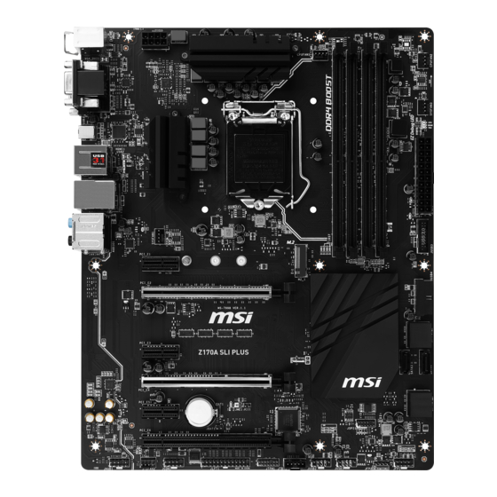
  • Seite 54: Übersicht Der Komponenten

    Übersicht der Komponenten DIMM3 DIMM2 DIMM4 SYSFAN1 DIMM1 CPUFAN1 JPWR2 CPU Sockel CPUFAN2 SYSFAN3 EZ Debug LED JPWR1 JUSB3 PCI_E1 M2_1 JUSB4 PCI_E2 SATA1_2 PCI_E3 SATA4 SATA3 PCI_E4 SATA5_6 PCI_E5 JCI1 JBAT1 PCI_E6 JFP1 JAUD1 JFP2 SYSFAN2 JUSB1 JCOM1 JUSB2 JLPT1 JTBT1* JTPM1...
  • Seite 55: Cpu Sockel

    Ziehen Sie das Netzkabel ab, bevor Sie CPU ein- und ausbauen. Bitte bewahren Sie die CPU Schutzkappe nach der Installation des Prozessors auf. MSI wird RMA (Return Merchandise Authorization) Anfragen nur dann behandeln, wenn die Schutzklappe auf dem CPU-Sockel des Motherboards sitzt.
  • Seite 56: Dimm-Steckplätze

    DIMM-Steckplätze DIMM1 DIMM3 Kanal A Kanal B DIMM2 DIMM4 Speichermodul-Installationsempfehlung DIMM4 DIMM4 DIMM3 DIMM2 DIMM2 DIMM2 DIMM1 Wichtig Um einen sicheren Systemstart zu gewährleisten, bestücken Sie immer DIMM2 zuerst. Aufgrund der Chipsatzressourcennutzung wird die verfügbare Kapazität des Speichers kleiner sein als die Größe der installierten Speicherkapazität. Basierend auf der Intel CPU Spezifikation wird eine Speicherspannung unter 1,35 Volt vorgeschlagen, um die CPU zu schützen.
  • Seite 57: Pci_E1~6: Pcie Erweiterungssteckplätze

    PCI_E1~6: PCIe Erweiterungssteckplätze PCI_E1: PCIe 3.0 x1-Steckplatz PCI_E2: PCIe 3.0 x16-Steckplatz PCI_E3: PCIe 3.0 x1-Steckplatz PCI_E4: PCIe 3.0 x8-Steckplatz PCI_E5: PCIe 3.0 x1-Steckplatz PCI_E6: PCIe 3.0 x4-Steckplatz Mehrere Grafikkarten Einbauempfehlung Wichtig Für die Installation einer einzelnen PCIe x16 Erweiterungskarte mit optimaler Leistung, empfehlen wir PCI_E2 Steckplatz zu verwenden.
  • Seite 58: Jaud1: Audioanschluss Des Frontpanels

    JAUD1: Audioanschluss des Frontpanels Dieser Anschluss ermöglicht den Anschluss von Audiobuchsen eines Frontpanels. MIC L Ground MIC R Head Phone R MIC Detection SENSE_SEND No Pin Head Phone L Head Phone Detection SATA1~6: SATA 6Gb/s Anschlüsse Diese Anschlüsse basieren auf der Hochgeschwindigkeitsschnittstelle SATA 6Gb/s. Pro Anschluss kann ein SATA Gerät angeschlossen werden.
  • Seite 59: M2_1: M.2 Steckplatz

    M2_1: M.2 Steckplatz Wichtig Intel RST unterstützt nur PCIe M.2 SSD mit UEFI ROM, ® Legacy-ROM wird NICHT unterstützt. Video-Demonstration Eine anschauliche Darstellung zur Installation eines M.2 Moduls finden Sie im Video. http://youtu.be/JCTFABytrYA Installation eines M.2 Moduls Entfernen Sie die Scharube aus dem Schraubsockel.
  • Seite 60: Jpwr1~2: Stromanschlüsse

    JPWR1~2: Stromanschlüsse Mit diesen Anschlüssen verbinden Sie die ATX Stromstecker. JPWR2 Ground +12V Ground +12V Ground +12V Ground +12V +3.3V +3.3V +3.3V -12V Ground Ground PS-ON# Ground Ground Ground JPWR1 Ground Ground PWR OK 5VSB +12V +12V +3.3V Ground Wichtig Stellen Sie sicher, dass alle Anschlüsse mit den richtigen Anschlüssen des Netzteils verbunden sind, um einen stabilen Betrieb der Hauptplatine sicherzustellen.
  • Seite 61: Jusb1~2: Usb 2.0 Anschlüsse

    Bitte beachten Sie, dass Sie die mit VCC (Stromführende Leitung) und Ground (Erdleitung) bezeichneten Pins korrekt verbinden müssen, ansonsten kann es zu Schäden kommen. Um das iPad, iPhone und iPod über USB-Anschlüsse aufzuladen, installieren Sie bitte die MSI SUPER CHARGER Software. ® JUSB3~4: USB 3.1 Gen1 Anschlüsse Mit diesen Anschlüssen können Sie die USB 3.1 Gen1 Anschlüsse auf dem Frontpanel...
  • Seite 62: Jfp1, Jfp2: Frontpanel-Anschlüsse

    JFP1, JFP2: Frontpanel-Anschlüsse Diese Anschlüsse verbinden mit den Schaltern und LEDs auf des Frontpanels. JFP1 HDD LED + Power LED + HDD LED - Power LED - Reset Switch Power Switch Reset Switch Power Switch Reserved No Pin Speaker - Buzzer + JFP2 Buzzer -...
  • Seite 63: Jci1: Gehäusekontaktanschluss

    JCI1: Gehäusekontaktanschluss Dieser Anschluss wird mit einem Kontaktschalter verbunden. Normal Trigger Gehäusekontakt (Standardwert) Event Gehäusekontakt-Detektor verwenden Schließen Sie den JCI1-Anschluss am Gehäusekontakt-Schalter/ Sensor am Gehäuse an. Schließen Sie die Gehäuseabdeckung. Gehen Sie zu BIOS > SETTINGS > Security > Chassis Intrusion Configuration. Stellen Sie Chassis Intrusion auf Aktiviert (Enabled).
  • Seite 64: Jlpt1: Parallele Schnittstelle

    JLPT1: Parallele Schnittstelle Mit dieser Schnittstelle können Sie das optionale parallele Schnittstelle mit dem Einbausatze verbinden. RSTB# AFD# PRND0 ERR# PRND1 PINIT# PRND2 LPT_SLIN# PRND3 Ground PRND4 Ground PRND5 Ground PRND6 Ground PRND7 Ground ACK# Ground BUSY Ground Ground SLCT No Pin JCOM1: Serieller Anschluss Mit diesem Anschluss können Sie das optionale serielle Schnittstelle mit dem...
  • Seite 65: Cpufan1~2, Sysfan1~3: Stromanschlüsse Für Lüfter

    CPUFAN1~2, SYSFAN1~3: Stromanschlüsse für Lüfter Diese Anschlüsse können im PWM (Pulse Width Modulation) Modus oder Spannungsmodus betrieben werden. Im PWM-Modus bieten die Lüfteranschlüsse konstante 12V Ausgang und regeln die Lüftergeschwindigkeit per Drehzahlsteuersignal. Im Spannungsmodus bestimmen die Lüfteranschlüsse die Lüftergeschwindigkeit durch Ändern der Spannung. Wenn Sie ein 3-Pin (Non-PWM) Lüfter an einen PWM-Modus Lüfteranschluss anschließen, läuft der Lüfter mit höchster Drehzahl und kann unangenehm laut werden.
  • Seite 66: Jbat1: Steckbrücke Zur Cmos-Löschung (Reset Des Bios)

    JBAT1: Steckbrücke zur CMOS-Löschung (Reset des BIOS) Der Onboard CMOS Speicher (RAM) wird durch eine externe Spannungsversorgung durch eine Batterie auf dem Motherboard versorgt, um die Daten der Systemkonfiguration zu speichern. Wenn Sie die Systemkonfiguration löschen wollen, müssen Sie die Steckbrücke für kurze Zeit umsetzen. Daten CMOS-Daten löschen/ Reset...
  • Seite 67: Bios-Setup

    Während des BOOT-Vorgangs drücken Sie die Taste Delete, wenn die Meldung Press DEL key to enter Setup Menu, F11 to enter Boot Menu erscheint. Verwenden Sie die MSI FAST BOOT Anwendung. Klicken Sie die GO2BIOS-Taste und drücken OK. Das System startet neu und geht direkt ins BIOS.
  • Seite 68: Reset Des Bios

    Aktualisierung des BIOS mit dem M-FLASH-Programm Vorbereitung: Laden Sie bitte die neueste BIOS Version, die dem Motherboard-Modell entspricht, von der offiziellen MSI Website herunter und speichern Sie die BIOS-Datei auf USB-Flash- Laufwerk. BIOS-Aktualisierungsschritte: Drücken Sie während des POST-Vorgangs die Taste (Entf), um das BIOS zu öffnen.
  • Seite 69: Ez Modus

    EZ Modus Im EZ-Modus können Sie die Grundinformationen des Systems einsehen und grundlegende Einstellungen konfigurieren. Um die erweiterten BIOS-Einstellungen anzeigen zu lassen, aktivieren Sie bitte den Erweiterten Modus durch Drücken des Setup Mode Schalter oder der Funktionstaste F7. XMP Schalter Setup Modus Schalter Screenshot Favoriten...
  • Seite 70 Favoriten - Drücken Sie eine beliebige Favoriten-Registerkarte oder die F3- Taste, um das Favoriten-Menü aufzurufen. Hier können Sie Ihre persönliches BIOS-Menü erstellen, in dem Sie die häufig verwendeten oder favorisierten BIOS- Einstellungsoptionen auswählen können. Default HomePage - Über diese Option können Sie ein BIOS-Menü (zum Beispiel: ƒ...
  • Seite 71: Erweiterten Modus

    Erweiterten Modus Drücken Sie den Setup Mode Schalter oder die Funkionstaste F7, um zwischen den EZ-Modus und Erweiterten-Modus im BIOS-Setup zu wechseln. XMP Schalter Setup Modus Schalter Screenshot Favoriten Sprache System- information Bootgeräte- Prioritätsleiste BIOS-Menü BIOS-Menü -Auswahl -Auswahl Menüanzeige XMP Schalter/ Setup Modus Schalter/ Screenshot/ Favoriten/ Sprache/ Systeminformation/ Boot-Geräte Prioritätsleiste - Die Beschreibungen zu diesen Funktionen finden Sie auf Seite 26 unter EZ-Modus.
  • Seite 72: Overclocking-Menü

    Overclocking-Menü In diesem Menü können Benutzer das BIOS anpassen und das Mainboard übertakten. Bitte führen Sie nur Änderungen durch, wenn Sie sich über das Ergebnis im Klaren sind. Sie sollten Erfahrung beim Übertakten haben, da Sie sonst das Motherboard oder Komponenten des Systems beschädigen können. Wichtig Die Übertaktung ist nur für fortgeschrittene Benutzer zu empfehlen.
  • Seite 73 Adjusted CPU Frequency Zeigt die eingestellte Frequenz der CPU an. Es handelt sich um eine Anzeige – Änderungen sind nicht möglich. Ring Ratio [Auto] Setzen Sie den Ring Ratio. Der erlaubte Wertebereich ist abhängig von der installierten CPU. Adjusted Ring Frequency Zeigt die angepasste Ring Frequenz.
  • Seite 74 Adjusted DRAM Frequency Zeigt die Speicherfrequenz an. Nur Anzeige – keine Änderung möglich. DRAM Timing Mode [Link] Wählt den Speicher-Timing-Modus aus. [Link] Ermöglicht die manuelle Konfigurieren des DRAM-Timing für alle Speicherkanäle. [UnLink] Ermöglicht die manuelle Konfigurieren des DRAM-Timing für die einzelnen Speicherkanäle.
  • Seite 75 PCH Voltage control [Auto] Erlaubt das Einstellen der PCH-Spannungen. Wenn die Einstellung auf Auto gesetzt ist, wird das BIOS die Spannungen automatisch einstellen oder Sie können es manuell einstellen. CPU Memory Changed Detect [Enabled]* Aktiviert/Deaktiviert die Systemwarnmeldung beim Booten, wenn die CPU oder der Hauptspeicher ersetzt wurde.
  • Seite 76 fExecute Disable Bit [Enabled] Intel’ s Execute Disable Bit kann an den Rechner gerichtete Buffer Overflow Angriffe verhindern, bei denen Computer-Würmer versuchen, das System durch Ausführung von Codes zu schädigen. Es wird empfohlen, diese Funktion zu aktivieren. [Enabled] Aktiviert den NO-Execution Schutz, um bösartigen Angriffe und Würmern abzuwehren.
  • Seite 77 fC1E Support [Disabled] Aktiviert oder deaktiviert die C1E-Funktion für Stromersparnis im Leerlauf. Diese Option wird angezeigt, wenn Intel C-State aktiviert ist. [Enabled] Ermöglicht die C1E Funktion, um die CPU-Frequenz und Spannung zur Stromersparnis im Leerlauf zu reduzieren. [Disabled] Deaktiviert diese Funktion. fPackage C State limit [Auto] Hier können Sie einen CPU C-State-Modus für Stromsparen auswählen, wenn das System im Leerlauf ist.
  • Seite 78: Softwarebeschreibung

    Installation von Treibern Starten Sie Ihren Computer mit Windows 7/ 8.1/ 10. ® Legen Sie die MSI Treiber Disk in das optisches Laufwerk. ® Der Installer wird automatisch erscheint und findet und finden Sie die benötigten Treiber in die Liste.
  • Seite 79 Table des matières Informations de sécurité ..................2 Spécifications ......................3 Panneau arrière Entrée/ Sortie ................8 Tableau explicatif de l’ état de la LED du port LAN ..........8 Configuration des ports audio ................8 Vue d’ ensemble des composants ............... 10 Socket processeur ....................
  • Seite 80: Informations De Sécurité

    Informations de sécurité Les composants dans l’ emballage peuvent être endommagés par des décharges électrostatiques (ESD). Pour vous assurer de correctement monter votre ordinateur, veuillez vous référer aux instructions ci-dessous. Assurez-vous de bien connecter tous les composants. En cas de mauvaise connexion, il se peut que l’...
  • Seite 81: Spécifications

    Mémoire Support Intel Extreme Memory Profile (XMP)** ® * Veuillez vous référer au site www.msi.com pour plus d’ informations sur la mémoire compatible. ** Du fait des limites du chipset Intel , les modules de mémoire DDR4 de 2133 ®...
  • Seite 82 Suite du tableau de la page précédente Chipset ASMedia ASM1142 ® 1 x port USB 3.1 Gen2 Type-C sur le panneau arrière ƒ Chipset Intel C236 ® 6 x ports USB 3.1 Gen1 (SuperSpeed USB) (2 ports sur le ƒ panneau arrière, 4 ports disponibles par l’...
  • Seite 83 Suite du tableau de la page précédente 1 x connecteur d’ alimentation principal ATX 24 broches 1 x connecteur d’ alimentation ATX 12V 8 broches 6 x connecteurs SATA 6 Gb/s 2 x connecteurs USB 2.0 (support de 4 autres ports USB 2.0) 2 x connecteurs USB 3.1 Gen1 (support de 4 autres ports USB 3.1 Gen1)
  • Seite 84 Suite du tableau de la page précédente Pilotes COMMAND CENTER LIVE UPDATE 6 SHORTCUT MANAGER FAST BOOT SUPER CHARGER Logiciel M-CLOUD RAMDISK Intel Extreme Tuning Utility ® Norton Security ™ Google Chrome ,Google Toolbar et Google Drive ™ CPU-Z CLICK BIOS 5 Possibilité...
  • Seite 85 Suite du tableau de la page précédente Support de DDR4 Boost Support mémoire DDR4 Dual-Channel ƒ Circuit DDR4 isolé ƒ Compatible XMP DDR4 ƒ Support PCI Express 3.0 Informations Support Nvidia SLI 2-Way ƒ supplémentaires Support AMD CrossFire 3-Way ƒ USB 3.1 Gen2 Compatible Compatible USB 3.1 Gen2 Type-C ƒ...
  • Seite 86: Panneau Arrière Entrée/ Sortie

    Panneau arrière Entrée/ Sortie Ports Audio USB 3.1 Gen 1 Souris PS/2 USB 3.1 Gen 2 Type-C USB 2.0 DVI-D Clavier PS/2 Tableau explicatif de l’ état de la LED du port LAN LED indiquant la connexion LED indiquant la vitesse et l’...
  • Seite 87 llustration de l’ utilisation des ports audio dédiés au casque et au microphone llustration de l’ utilisation du port audio dédié aux haut-parleurs AUDIO INPUT llustration de l’ utilisation des ports audio dédiés aux haut-parleurs 7.1 AUDIO INPUT Rear Front Side Center/ Subwoofer...
  • Seite 88: Vue D' Ensemble Des Composants

    Vue d’ ensemble des composants DIMM3 DIMM2 DIMM4 SYSFAN1 DIMM1 Socket CPUFAN1 JPWR2 processeur CPUFAN2 SYSFAN3 EZ Debug LED JPWR1 JUSB3 PCI_E1 M2_1 JUSB4 PCI_E2 SATA1_2 PCI_E3 SATA4 SATA3 PCI_E4 SATA5_6 PCI_E5 JCI1 JBAT1 PCI_E6 JFP1 JAUD1 JFP2 SYSFAN2 JUSB1 JCOM1 JUSB2 JLPT1...
  • Seite 89: Socket Processeur

    électrique. Veuillez garder le capot de protection du processeur après l’ installation du processeur. Selon les exigences de RMA (Return Merchandise Authorization), MSI n’ acceptera pas les cartes mère dont le capot de protection aura été retiré.
  • Seite 90: Slots Dimm

    Slots DIMM DIMM1 DIMM3 Canal A Canal B DIMM2 DIMM4 Installation recommendée de module mémoire DIMM4 DIMM4 DIMM3 DIMM2 DIMM2 DIMM2 DIMM1 Important Veillez à toujours insérer un module de mémoire dans l’ emplacement DIMM2 en premier. Du fait des ressources utilisées par le chipset, la capacité de mémoire disponible est un peu moins élevée que celle installée.
  • Seite 91: Pci_E1~6: Slots D'extension Pcie

    PCI_E1~6: Slots d'extension PCIe PCI_E1: slot PCIe 3.0 x1 PCI_E2: slot PCIe 3.0 x16 PCI_E3: slot PCIe 3.0 x1 PCI_E4: slot PCIe 3.0 x8 PCI_E5: slot PCIe 3.0 x1 PCI_E6: slot PCIe 3.0 x4 Installation recommandée pour une configuration multi-GPU Important Si vous choisissez d’...
  • Seite 92: Jaud1: Connecteur Audio Avant

    JAUD1: Connecteur audio avant Ce connecteur se lie aux jacks audio du panneau avant. MIC L Ground MIC R Head Phone R MIC Detection SENSE_SEND No Pin Head Phone L Head Phone Detection SATA1~6: Connecteurs SATA 6 Gb/s Ces connecteurs utilisent une interface SATA 6 Gb/s. Chaque connecteur peut être relié...
  • Seite 93: M2_1: Slots M.2

    M2_1: Slots M.2 Important La technologie Intel RST supporte seulement un SSD ® M.2 PCIe avec une mémoire ROM UEFI et non avec une mémoire ROM Legacy. Vidéo de démonstration Référez-vous à la vidéo d’ instruction sur l’ installation du module M.2. http://youtu.be/JCTFABytrYA Installation du module M.2 Enlevez la vis de la vis...
  • Seite 94: Jpwr1~2: Connecteurs D' Alimentation

    JPWR1~2: Connecteurs d’ alimentation Ces connecteurs vous permettent de relier une alimentation ATX. JPWR2 Ground +12V Ground +12V Ground +12V Ground +12V +3.3V +3.3V +3.3V -12V Ground Ground PS-ON# Ground Ground Ground JPWR1 Ground Ground PWR OK 5VSB +12V +12V +3.3V Ground Important...
  • Seite 95: Jusb1~2: Connecteurs Usb 2.0

    Notez que les broches VCC et Terre doivent être branchées correctement afin d’ éviter tout dommage sur la carte mère. Pour recharger votre tablette, smartphone ou autre périphérique par l’ intermédiaire d’ un port USB, veuillez installer l’ utilitaire MSI SUPER CHARGER. ®...
  • Seite 96: Jfp1, Jfp2: Connecteurs Panneau Avant

    JFP1, JFP2: Connecteurs panneau avant Ces connecteurs se lient aux interrupteurs et indicateurs LED du panneau avant. JFP1 HDD LED + Power LED + HDD LED - Power LED - Reset Switch Power Switch Reset Switch Power Switch Reserved No Pin Speaker - Buzzer + JFP2...
  • Seite 97: Jci1: Connecteur Intrusion Châssis

    JCI1: Connecteur intrusion châssis Ce connecteur est relié à un câble d’ interrupteur intrusion châssis. Normal Commencer l’ activité intrusion châssis (défaut) Utilisation du détecteur d’ intrusion châssis Reliez le connecteur JCI1 à l’ interrupteur ou au capteur d’ intrusion châssis situé sur le boîtier du PC.
  • Seite 98: Jlpt1: Connecteur De Port Parallèle

    JLPT1: Connecteur de port parallèle Ce connecteur sert à connecter un support de port parallèle optionnel. RSTB# AFD# PRND0 ERR# PRND1 PINIT# PRND2 LPT_SLIN# PRND3 Ground PRND4 Ground PRND5 Ground PRND6 Ground PRND7 Ground ACK# Ground BUSY Ground Ground SLCT No Pin JCOM1: Connecteur de port série Ce connecteur vous permet de relier un port série en option.
  • Seite 99: Cpufan1~2, Sysfan1~3: Connecteurs Pour Ventilateurs

    CPUFAN1~2, SYSFAN1~3: Connecteurs pour ventilateurs Les connecteurs pour ventilateurs peuvent être utilisés en mode PWM (Pulse Width Modulation) et en mode tension. En mode PWM, les connecteurs fournissent une sortie de 12V constante et ajustent la vitesse des ventilateurs avec un signal de contrôle de vitesse.
  • Seite 100: Jbat1: Cavalier Clear Cmos (Réinitialisation Bios)

    JBAT1: Cavalier clear CMOS (Réinitialisation BIOS) Une mémoire CMOS est intégrée et est alimentée en externe par une batterie située sur la carte mère afin de conserver les données de configuration système. Si vous souhaitez nettoyer la configuration système, placez le cavalier sur Effacer CMOS de manière à...
  • Seite 101: Configuration Du Bios

    Menu, F11 to enter Boot Menu” sur l’ écran, veuillez appuyer sur la touche Suppr. Quand l’ ordinateur est déjà en marche, vous pouvez utiliser l’ application MSI FAST BOOT. Cliquez sur le bouton GO2BIOS puis sur OK. Le système redémarre et entre dans l’...
  • Seite 102: Réinitialiser Le Bios

    Avant la mise à jour : Veuillez télécharger la dernière version de BIOS compatible à votre carte mère sur le site MSI. Ensuite, veuillez sauvegarder le nouveau BIOS sur le lecteur flash USB. Mettre le BIOS à jour : Appuyez sur la touche Suppr pour entrer dans l’ interface Setup du BIOS pendant le processus de POST.
  • Seite 103: Ez Mode (Mode Simplifié)

    EZ Mode (mode simplifié) Le mode EZ vous fournit les informations basiques du système et vous permet de configurer les réglages de base. Si vous souhaitez configurer les réglages du BIOS, veuillez utiliser le mode Advanced en appuyant sur le switch Setup Mode ou la touche de fonction F7.
  • Seite 104 XMP switch (interrupteur XMP) - cliquez sur le cercle intérieur pour activer ou désactiver le profil XMP (Extreme Memory Profile). Cliquez sur le cercle extérieur pour choisir le profil XMP. Cet interrupteur est seulement disponible si le profil XMP supporte le module de mémoire installé. Favorites (Favoris) - appuyez sur n’...
  • Seite 105: Advanced Mode (Mode Avancé)

    Advanced Mode (mode avancé) Appuyez sur le Setup Mode switch (interrupteur de modes de réglages) ou sur la touche de fonction F7 pour commuter entre le mode simplifié et le mode avancé. XMP switch Setup Mode switch Screenshot Favorites Language System information Boot device...
  • Seite 106: Oc Menu (Menu Overclocking)

    OC Menu (menu overclocking) Ce menu est destiné aux utilisateurs avancés souhaitant overclocker leur carte mère. Important L’ overclocking manuel du PC n’ est recommandé que pour les utilisateurs avancés. L’ overclocking n’ est pas garanti et une mauvaise manipulation peut rendre nulle votre garantie et sévèrement endommager votre matériel.
  • Seite 107 Adjusted Ring Frequency Montre la fréquence Ring modifiée. Fonctionne uniquement en lecture seule. GT Ratio [Auto] Règle le ratio de la puce graphique intégrée. La gamme de valeur valides dépend du processeur installé. Adjusted GT Frequency Montre la fréquence de la puce graphique intégrée modifiée. Fonctionne uniquement en lecture seule.
  • Seite 108 DRAM Timing Mode [Link] Choisit le mode de latences mémoire. [Link] Ceci vous permet de configurer manuellement les latences de la mémoire de toutes les barrettes de mémoire. [UnLink] Ceci vous permet de configurer manuellement les latences pour chaque barrette de mémoire individuelle. Advanced DRAM Configuration Appuyez sur la touche Entrée pour entrer dans le sous-menu.
  • Seite 109 [Enabled] Le système montre un message d'alerte pendant le démarrage et vous devez charger les réglages par défaut pour les nouveaux périphériques. [Disabled] Désactive cette fonction et garde les réglages BIOS actuels. CPU Specifications Appuyez sur la touche [Entrée] pour accéder au sous-menu. Ce sous-menu affiche les caractéristiques du processeur installé.
  • Seite 110 fIntel Virtualization Tech [Enabled] Active ou désactive la technologie Intel Virtualization. [Enabled] Active la technologie Intel Virtualization et autoriser une plate-forme visant à faire fonctionner plusieurs systèmes d'exploitation dans des partitions indépendentes. Le système peut fonctionner virtuellement comme des systèmes multiples. [Disabled] Désactive cette fonction.
  • Seite 111 fPackage C-State limit [Auto] Ce menu permet de choisir un mode C-state du processeur pour économiser l’ énergie lorsque le système est en veille. Ce menu apparaît lorsque la fonction Intel C-State est activée. fCFG Lock [Enabled] Verrouille ou déverrouille la fonction MSR 0xE2[15], CFG lock bit. [Enabled] Verrouille le CFG lock bit.
  • Seite 112: Informations Sur Les Logiciels

    ® Installer les pilotes Allumez l’ ordinateur sous Windows 7/ 8.1/ 10. ® Insérez le disque MSI Driver dans le lecteur optique. ® L’ outil d’ installation apparaît automatiquement. Il trouvera et listera tous les pilotes dont vous avez besoin.
  • Seite 113 Содержание Безопасное использование продукции ............. 2 Технические характеристики ................3 Задняя панель ввода/ вывода ................7 Таблица состояния индикатора порта LAN ............7 Конфигурация портов Аудио ................. 7 Компоненты материнской платы ............... 9 Процессорный сокет ................... 10 Слоты DIMM ......................11 PCI_E1~6: Слоты...
  • Seite 114: Безопасное Использование Продукции

    Безопасное использование продукции Компоненты, входящие в комплект поставки могут быть повреждены статическим электричеством. Для успешной сборки компьютера, пожалуйста, следуйте указаниям ниже. Убедитесь, что все компоненты компьютера подключены должным образом. Ослабленные соединения компонентов могут привести как к сбоям в работе, так и...
  • Seite 115: Технические Характеристики

    Поддержка Intel Extreme Memory Profile (XMP)** ® * Для получения дополнительной информации о совместимых модулях памяти, пожалуйста, посетите www.msi.com. ** Из-за ограничений, накладываемых чипсетом Intel , модули памяти ® DDR4 2133 МГц и выше, в режиме XMP, будут работать на максимальной...
  • Seite 116 Продолжение с предыдущей страницы Чипсет ASMedia ASM1142 ® 1x порт USB 3.1 Gen2 Type-C на задней панели ƒ Чипсет Intel C236 ® 6x портов USB 3.1 Gen1 (SuperSpeed USB) (2 порта на ƒ задней панели, 4 порта доступны через внутренние USB разъемы) 6x портов...
  • Seite 117 Продолжение с предыдущей страницы Контроллер ввода- NUVOTON NCT6793 вывода Определение температуры процессора/системы Определение скорости вентиляторов процессора/ Аппаратный системы мониторинг Управление скоростью вентиляторов процессора/ системы ATX Форм-фактор Форм-фактор 12 x 9.6 дюйма (30.5 x 24.4 см) 1x 128 Мб флэш UEFI AMI BIOS Параметры...
  • Seite 118 Стабильность и надежность в соответсветствии с ƒ военными стандартами Military Class Защита от электростатических разрядов ˜ Защита от электромагнитных помех ˜ Защита от влажности ˜ MSI Эксклюзивные Защита от замыканий ˜ функции Защита от высокой температуры ˜ Слоты Steel Armor PCIe ˜ Слот VGA Armor ˜...
  • Seite 119: Задняя Панель Ввода/ Вывода

    Задняя панель ввода/ вывода Порты Аудио USB 3.1 Gen 1 PS/2 мышь USB 3.1 Gen 2 Type-C USB 2.0 DVI-D PS/2 клавиатура Таблица состояния индикатора порта LAN Подключение/ Работа Скорость передачи данных индикатора Состояние Описание Состояние Описание Выкл. 10 Мбит/с подключение Выкл.
  • Seite 120 Подключение наушников и микрофона Подключение внешнего стерео усилителя (колонок) AUDIO INPUT Подключение звуковой системы 7.1 AUDIO INPUT Rear Front Side Center/ Subwoofer Задняя панель ввода/ вывода...
  • Seite 121: Компоненты Материнской Платы

    Компоненты материнской платы DIMM3 DIMM2 DIMM4 SYSFAN1 DIMM1 CPUFAN1 Процессорный JPWR2 сокет CPUFAN2 SYSFAN3 EZ Debug LED JPWR1 JUSB3 PCI_E1 M2_1 JUSB4 PCI_E2 SATA1_2 PCI_E3 SATA4 SATA3 PCI_E4 SATA5_6 PCI_E5 JCI1 PCI_E6 JBAT1 JFP1 JAUD1 JFP2 SYSFAN2 JUSB1 JCOM1 JUSB2 JLPT1 JTBT1* JTPM1...
  • Seite 122: Процессорный Сокет

    кабель питания. Пожалуйста, сохраните защитную крышку процессорного сокета после установки процессора. Любые возможные гарантийные случаи, связанные с работой материнской платы, MSI будет рассматривать только, при наличии защитной крышки на процессорном сокете. При установке процессора обязательно установите процессорный кулер. Кулер, представляющий собой систему охлаждения процессора, предупреждает...
  • Seite 123: Слоты Dimm

    Слоты DIMM DIMM1 DIMM3 Канал A Канал B DIMM2 DIMM4 Рекомендации по установке модулей памяти DIMM4 DIMM4 DIMM3 DIMM2 DIMM2 DIMM2 DIMM1 Внимание! Всегда устанавливайте модуль памяти сначала в слот DIMM2. В связи со спецификой использования ресурсов чипсета, доступный объем памяти...
  • Seite 124: Pci_E1~6: Слоты Расширения Pcie

    PCI_E1~6: Слоты расширения PCIe PCI_E1: PCIe 3.0 x1 слот PCI_E2: PCIe 3.0 x16 слот PCI_E3: PCIe 3.0 x1 слот PCI_E4: PCIe 3.0 x8 слот PCI_E5: PCIe 3.0 x1 слот PCI_E6: PCIe 3.0 x4 слот Рекомендации по установке нескольких видеокарт Внимание! Для...
  • Seite 125: Jaud1: Разъем Аудио Передней Панели

    JAUD1: Разъем аудио передней панели Данный разъем предназначен для подключения аудиоразъемов передней панели. MIC L Ground MIC R Head Phone R MIC Detection SENSE_SEND No Pin Head Phone L Head Phone Detection SATA1~6: Разъемы SATA 6 Гб/с Эти разъемы представляют собой интерфейсные порты SATA 6 Гб/с. К каждому порту...
  • Seite 126 M2_1: Разъем M.2 Внимание! Intel RST поддерживает только PCIe M.2 SSD с UEFI ® ROM, и не поддерживает Legacy ROM. Видео Инструкция Смотрите видео, чтобы узнать как установить модуль M.2. http://youtu.be/JCTFABytrYA Установка модуля M.2 Выкрутите винт из базового винта. Выкрутите базовый винт.
  • Seite 127: Jpwr1~2: Разъемы Питания

    JPWR1~2: Разъемы питания Данные разъемы предназначены для подключения коннекторов питания ATX. JPWR2 Ground +12V Ground +12V Ground +12V Ground +12V +3.3V +3.3V +3.3V -12V Ground Ground PS-ON# Ground Ground Ground JPWR1 Ground Ground PWR OK 5VSB +12V +12V +3.3V Ground Внимание! Для...
  • Seite 128: Jusb1~2: Разъемы Usb 2.0

    Внимание! Помните, что во избежание повреждений необходимо правильно подключать контакты VCC и Ground. Для того, чтобы зарядить ваш iPad, iPhone и iPod портами USB, пожалуйста, установите утилиту MSI SUPER CHARGER. ® JUSB3~4: Разъемы USB 3.1 Gen1 Данные разъемы предназначены для подключения портов USB 3.1 Gen1 на...
  • Seite 129: Jfp1, Jfp2: Разъемы Передней Панели

    JFP1, JFP2: Разъемы передней панели Эти разъемы служат для подключения кнопок и светодиодных индикаторов, расположенных на передней панели. JFP1 HDD LED + Power LED + HDD LED - Power LED - Reset Switch Power Switch Reset Switch Power Switch Reserved No Pin Speaker - Buzzer +...
  • Seite 130: Jci1: Разъем Датчика Открытия Корпуса

    JCI1: Разъем датчика открытия корпуса К этому разъему подключается кабель от датчика открытия корпуса. Нормально Разрешить запись по событию открытия (По умолчанию) корпуса Использование датчика открытия корпуса Подключите подключите датчик открытия корпуса к разъему JCI1. Закройте крышку корпуса. Войдите в BIOS > SETTINGS > Security > Chassis Intrusion Configuration. Установите...
  • Seite 131: Jlpt1: Разъем Параллельного Порта

    JLPT1: Разъем параллельного порта Этот разъем позволяет подключить параллельный порт, размещенный на внешнем брекете. RSTB# AFD# PRND0 ERR# PRND1 PINIT# PRND2 LPT_SLIN# PRND3 Ground PRND4 Ground PRND5 Ground PRND6 Ground PRND7 Ground ACK# Ground BUSY Ground Ground SLCT No Pin JCOM1: Разъем...
  • Seite 132: Cpufan1~2, Sysfan1~3: Разъемы Вентиляторов

    CPUFAN1~2, SYSFAN1~3: Разъемы вентиляторов Разъемы вентиляторов можно разделить на два типа: с PWM (PulseWidth Modulation) управлением и управлением постоянным током. Разъемы вентиляторов с PWM управлением имею контакт с постоянным напряжением 12В, а также контакт с сигналом управления скоростью вращения. Управление скоростью вращения...
  • Seite 133: Jbat1: Джампер Очистки Данных Cmos (Сброс Bios)

    JBAT1: Джампер очистки данных CMOS (Сброс BIOS) На плате установлена CMOS память с питанием от батарейки для хранения данных о конфигурации системы. Для сброса конфигурации системы (очистки данных CMOS памяти), воспользуйтесь этим джампером. Сохранение Очистка данных/ данных Сброс BIOS (По умолчанию) Сброс...
  • Seite 134: Настройка Bios

    Нажмите клавишу Delete, когда появляется сообщение на экране Press DEL key to enter Setup Menu, F11 to enter Boot Menu во время загрузки. При помощи приложения MSI FAST BOOT. Нажмите на кнопку GO2BIOS и выберите OK. Система перезагрузится и автоматически войдет в настройки...
  • Seite 135: Сброс Bios

    джампера/ кнопки очистки данных CMOS. Обновление BIOS Обновление BIOS при помощи M-FLASH Подготовительные операции: Пожалуйста, скачайте последнюю версию файла BIOS с сайта MSI, который соответствует вашей модели материнской платы. Сохраните файл BIOS в флэш- диске USB. Обновление BIOS: Нажмите клавишу Del для входа в настройки BIOS во время процедуры POST.
  • Seite 136: Режим Ez

    Режим EZ Режим EZ представляет основную информацию о системем и позволяет выполнить основные операции по настройке. Для настройки расширенных функций BIOS, пожалуйста, войдите в Расширенный режим, путем нажатия Переключатель режимов установки или функциональной клавиши F7. Переключатель режимов установки Переключатель XMP Скриншот...
  • Seite 137 Избранное - нажмите любую вкладку Избранное или клавишу F3 для входа в меню Избранное. Позволяет создать личное меню BIOS, где вы можете сохранить и получить доступ к вашим любимым и часто используемым настройкам BIOS. Главная страница по умолчанию - позволяет выбрать меню BIOS (например, ƒ...
  • Seite 138: Режим Разгона

    Режим разгона Нажмите переключатель режимов установки или функциональную клавишу F7 для переключения между режимами EZ и разгона в настройки BIOS. Переключатель режимов установки Переключатель XMP Скриншот Избранное Язык Информация о системе Приоритет загрузочных устройств Выбор меню Выбор меню BIOS BIOS Экран...
  • Seite 139: Меню Oc

    Меню OC Данное меню предназначено для опытных пользователей и предоставляет возможности для «разгона» системы. Внимание! Разгонять ПК вручную рекомендуется только опытным пользователям. Производитель не гарантирует успешность разгона. Неправильное выполнение разгона может привести к аннулированию гарантии и серьезному повреждению оборудования. OC Explore Mode [Normal] Включение...
  • Seite 140 Adjusted CPU Frequency Показывает текущую частоту процессора. Это значение нельзя изменять. Ring Ratio [Auto] Установка множителя кольцевой шины. Диапазон допустимых значений зависит от установленного процессора. Adjusted Ring Frequency Показывает измененную частоту шины Ring. Это значение нельзя изменять. GT Ratio [Auto] Установка...
  • Seite 141 Adjusted DRAM Frequency Показывает текущую частоту DRAM. Это значение нельзя изменять. DRAM Timing Mode [Link] Режимы таймингов памяти. [Link] Позволяет пользователю настроить тайминги DRAM для всех каналов памяти. [UnLink] Позволяет пользователю настроить тайминги DRAM для соответствующего канала памяти. Advanced DRAM Configuration Нажмите...
  • Seite 142 DRAM Voltage(s) control [Auto] Эти пункты позволяют вам задать напряжения, связанные с памятью. При установке в Auto, BIOS установит напряжения автоматически. Вы также можете настроить напряжения вручную. PCH Voltage control [Auto] Этот параметр позволяет вам задать напряжения, связанные с PCH. При установке в...
  • Seite 143 fLimit CPUID Maximum [Disabled] Включение или выключение расширенных значений CPUID. [Enabled] BIOS будет ограничивать максимальное входное значение CPUID для обхода проблемы загрузки в устаревших операционных системах, не поддерживающих процессор с расширенными значениями CPUID. [Disabled] Используйте фактическое максимальное входное значение CPUID. fExecute Disable Bit [Enabled] Функция...
  • Seite 144 fIntel Adaptive Thermal Monitor [Enabled] Включение или выключение адаптивного температурного мониторинга для защиты процессора от перегрева. [Enabled] Уменьшает частоту ядра процессра, когда процессор превышает адаптивную температуру. [Disabled] Выключение функции. fIntel C-State [Auto] Включение или выключение Intel C-state. C-state - это технология управления питанием...
  • Seite 145 fLong Duration Power Limit (W) [Auto] Настроить предельную мощность TDP процессора для длительной работы в режиме Turbo Boost. fLong Duration Maintained (s) [Auto] Настроить максимальное время работы процессора с ограничением мощности при Long Duration Power Limit. fShort Duration Power Limit (W) [Auto] Настроить...
  • Seite 146: Описание Программного Обеспечения

    7/ 8.1/ 10. ® Установка драйверов Загрузите компьютер в Windows 7/ 8.1/ 10. ® Вставьте диск с драйверами MSI Driver Disc в привод для оптических дисков. ® Автоматически отобразится окно установщика, который найдет и перечислит все необходимые драйверы. Нажмите кнопку Install.
  • Seite 147: Regulatory Notices

    EU REACH Regulation (Regulation EC No. 1907/2006 of the European Parliament and the This device complies with part 15 of the FCC Rules. Council), MSI provides the information of chemical Operation is subject to the following two conditions: substances in products at: (1) This device may not cause harmful interference, and http://www.msi.com/html/popup/csr/evmtprtt_pcm.
  • Seite 148 MSI will comply with the product take entregar a una empresa autorizada para la recogida de back requirements at the end of life of MSI-branded estos residuos.
  • Seite 149: Environmental Policy

    MSI si adeguerà a tale Direttiva ritirando tutti i prodotti marchiati MSI che sono stati venduti all’interno dell’Unione Europea alla fine del loro ciclo di vita.
  • Seite 150: Revision History

    Alternatively, please try the following help resources for further guidance. y Visit the MSI website for technical guide, BIOS updates, driver updates, and other information: http://www.msi.com y Register your product at: http://register.msi.com...

Inhaltsverzeichnis