Herunterladen Inhalt Inhalt Diese Seite drucken
Inhaltsverzeichnis

Werbung

Verfügbare Sprachen

Verfügbare Sprachen

Operating Instructions
Bedienungsanleitung
Instructions de Service
Type 8633
Mini TOP

Werbung

Inhaltsverzeichnis
loading

Inhaltszusammenfassung für bürkert Mini TOP 8633

  • Seite 1 Operating Instructions Bedienungsanleitung Instructions de Service Type 8633 Mini TOP...
  • Seite 2 We reserve the right to make technical changes without notice. Technische Änderungen vorbehalten. Sous resérve de modification techniques. © 2000 Bürkert Werke GmbH & Co. KG Operating Instructions 0507/09_EU-ML_00803925...
  • Seite 3: Inhaltsverzeichnis

    ONTENTS Contents of the operating instruction of the MiniTOP type 8633 GENERAL INFORMATION ........................................Symbols .................................................. Safety information ........................................... Scope of delivery ............................................Warranty guarantee ..........................................TECHNICAL DATA ............................................Design and function ..........................................Features ..................................................Operating conditions ......................................... Compliance ..............................................Mechanical Data ............................................
  • Seite 4 ONTENTS 2 - 8633...
  • Seite 5: General Information

    ENERAL NFORMATION GENERAL INFORMATION Symbols .................................................. Safety information ........................................... Scope of delivery ............................................Warranty guarantee ..........................................8633 - 3...
  • Seite 6: Symbols Used

    ENERAL NFORMATION Symbols used The following symbols will be used in these operating instructions Marks a working step that must be carried out ATTENTION! Indicates information that must be followed. Failure to do this could endanger your health or the functionality of the device NOTE Indicates important additional information, tips and recommendations Safety information...
  • Seite 7: Scope Of Delivery

    ENERAL NFORMATION Scope of delivery Immediately after receiving the shipment, ensure that the contents are undamaged and correspond to the scope of the delivery listed on the enclosed packing note. In general, the delivery consists of: • the MiniTOP alternatively: •...
  • Seite 8 ENERAL NFORMATION 6 - 8633...
  • Seite 9: Technical Data

    ECHNICAL TECHNICAL DATA Design and function ..........................................Features ................................................Operating conditions ........................................Compliance ..............................................Mechanical data ............................................. Pneumatical data ..........................................Electrical data without bus drive .................................. Electrical data with bus drive (AS-Interface) ..........................8633 - 7...
  • Seite 10 ECHNICAL Design and function of the MiniTOP The MiniTOP 8633 is designed for the operation of pneumatically actuated process valves. It can be combined with various types of valve from the Bürkert process valve range (see the data sheets for the types 2000, 2001, 2002, 2012, 2030, 2031, 2031K, 2652, 2655 and 2658).
  • Seite 11 ECHNICAL Features Design For single or double-acting valve actuators Control valve Using solenoid valves with the rocker principle: 1 x 3/2 way control valve with single-acting valve drive 2 x 32-way control valve with double-acting valve drive Electrical interface Metric cable bushings with screw terminals; Multipol round connector, 12-pole (on request);...
  • Seite 12: Operating Conditions

    ECHNICAL Operating conditions Operating temperature 0 ... + 55 °C Protection class IP 65 according to EN 60529 Conformity with following standards CE Mark Conformity with regard to the EMC directive directive 89/336/EWG (only for correctly connected cable and/or plug and socket) Mechanical data Dimensions see data sheet...
  • Seite 13 ECHNICAL Electrical data without bus control Connections metric cable bushings M16 with screw terminal Electrical supply 24 V DC ± 10 % Residual ripple 10 % for inductive proximity switches 110 V AC ± 10 %, 230 V AC ± 10 % Power consumption Voltage single working...
  • Seite 14 ECHNICAL 12 - 8633...
  • Seite 15: Commissioning

    OMMISSIONING COMMISSIONING Fluid installation ................................................. Electrical installation ............................................8633 - 13...
  • Seite 16: Fluidic Installation

    OMMISSIONING Fluidic installation The dimensions of the MiniTOP and the various complete device variants, consisting of MiniTOP, pneumatic actuator and valve, can be taken from the respective data sheets. Installation of the valve Dimensions and thread types can be taken from the data sheet of the process valve. Mounting the MiniTOP 8633 on the valve actuator General notes The MiniTOP 8633 is mounted on the valve actuator and the switching points of the limit switches are set...
  • Seite 17 OMMISSIONING Supply pressure 2-10 bar Service port 1 Service port 2 (with double-acting actuators) Setscrew SW2 Upper cam (plastic bond upward) Signal part Lower cam (plastic bond downward) Transparent cover O-ring Brass guide piece Plastic part of switching spindle Piston rod of actuator Actuator Figure: Mounting the MiniTOP Place MiniTOP on top.
  • Seite 18 OMMISSIONING Clamp the MiniTOP securely with the 2 setscrews (socket head SW2; fixing torque 0.2 ... 0.4 Nm). Screw the plugged hose connectors onto the MiniTOP and the valve actuator. Using the hoses supplied in the accessory kit, make the pneumatic connection between MiniTOP and valve actuator.
  • Seite 19: Opening The Housing

    OMMISSIONING To do this, proceed as follows: First disconnect the device from the electrical and pneumatic supplies! Undo the fluid connections between the MiniTOP and the pneumatic drive. Undo the threaded pins inset into the side of the housing using (SW 2 Allen key).
  • Seite 20: Electrical Installation

    OMMISSIONING Electrical installation A metrical cable bushings duct is available for the electrical connections to the MiniTOP Type 8633. For units that work with protective low voltage ( ≤ 48 V), a model with a Multipol connection is in preparation. Connection terminals for metric cable bushing screw fittings NOTE Limit switches:...
  • Seite 21 OMMISSIONING 24 V variant with inductive proximity switches (normally open) Terminal Connection External circuit Supply for proximity switch +24 V +24 V DC Supply for proximity switch GND (Residual ripple 10%) Output 1 (0V/24V) Binary output, proximity switch 1 (NO) Output 2 (0V/24V) not used Reference for proximity switch 1 GND...
  • Seite 22 OMMISSIONING 110 V and 230 V variant with mechanical limit switches Terminal Connection External circuit Supply for limit switch Supply for limit switch NC1 (max. 5 A) Output, limit switch 1 (NO) NO1 (max. 5 A) Output, limit switch 1 (NC) NC2 (max.
  • Seite 23: Bus Drive Via As-Interface

    OMMISSIONING Bus drive via AS-interface standard Device Device for A/B-Slave addressing Certification: Approval no. 31902 (to V.2.1) none Programming data: E/A-configuration B hex (1 output, 2 inputs) ID-Code F hex (see under for pin A hex (see under for pin configuration) configuration) ext.
  • Seite 24: Electrical Connection

    OMMISSIONING (yellow) (yellow) Valve supplied with power Limit switch 1 tripped (Upper limit position reached) (green) (yellow) Status display LED 1 ASI bus Limit switch 2 tripped (red) (Lower limit position Status display LED 2 ASI bus reached) Fig.: Circuit board the MiniTOP, AS interface variant Electrical connection 4-pole M12 round plug: Pin 1: Bus +...
  • Seite 25: Safety Positions And Maintenance

    AFETY POSITIONS AND MAINTENANCE SAFETY POSITIONS MAINTENANCE Safety positions following a loss of the electrical and/or pneumatic auxiliary ..................Maintenance ..............................................8633 - 23...
  • Seite 26: Safety Positions Following A Loss Of The Electrical And/Or Pneumatic Auxiliary

    AFETY POSITIONS AND MAINTENANCE Safety positions following a loss of the electrical and/or pneumatic auxiliary supply Safety position after loss of the auxiliary supply Type of drive Description electrical pneumatic single-working down down WW A down single-working WW B WW B down down / up not defined...
  • Seite 27 AFETY POSITIONS AND MAINTENANCE Notes 8633 - 25...
  • Seite 28 AFETY POSITIONS AND MAINTENANCE 26 - 8633...
  • Seite 29 NHALT Inhaltsverzeichnis der Gesamtbetriebsanleitung des MiniTOP Typ 8633 ALLGEMEINE HINWEISE ........................................Darstellungsmittel ..........................................Sicherheitshinweise .......................................... Lieferumfang ..............................................Garantiebestimmungen ....................................... TECHNISCHE DATEN ..........................................Aufbau und Funktion ........................................Merkmale ................................................Betriebsbedingungen ........................................Konformität ..............................................Mechanische Daten ..........................................Pneumatische Daten ......................................... Elektrische Daten ohne Busansteuerung ............................
  • Seite 30 NHALT 28 - 8633...
  • Seite 31: Allgemeine Hinweise

    LLGEMEINE INWEISE ALLGEMEINE HINWEISE Darstellungsmittel ..........................................Sicherheitshinweise .......................................... Lieferumfang ..............................................Garantiebestimmungen ....................................... 8633 - 29...
  • Seite 32: Sicherheitshinweise

    LLGEMEINE INWEISE Darstellungsmittel In dieser Betriebsanleitung werden folgende Darstellungsmittel verwendet: markiert einen Arbeitsschritt, den Sie ausführen müssen ACHTUNG! kennzeichnet Hinweise, bei deren Nichtbeachtung Ihre Gesundheit oder die Funktions- fähigkeit des Gerätes gefährdet ist. HINWEIS kennzeichnet wichtige Zusatzinformationen, Tipps und Empfehlungen. Sicherheitshinweise Bitte beachten Sie die Hinweise dieser Betriebsanleitung sowie die Einsatzbedingungen und zulässigen Daten, die in den Datenblättern des MiniTOP sowie des jeweils pneumatisch betätigten Ventils spezifi-...
  • Seite 33: Lieferumfang

    LLGEMEINE INWEISE Lieferumfang Überzeugen Sie sich unmittelbar nach Erhalt der Sendung, dass der Inhalt nicht beschädigt ist und mit dem auf dem beigelegten Packzettel angegebenen Lieferumfang übereinstimmt. Generell besteht dieser aus: • dem MiniTOP Typ 8633 alternativ: • pneumatisch betätigtem Prozessventil der Typen 2000, 2001, 2002, 2012, 2030, 2031, 2031K, 2652, 2655, 2658.
  • Seite 34 LLGEMEINE INWEISE 32 - 8633...
  • Seite 35: Technische Daten

    ECHNISCHE ATEN TECHNISCHE DATEN Aufbau und Funktion ......................................... Merkmale ................................................Betriebsbedingungen ........................................Konformität ..............................................Mechanische Daten ..........................................Pneumatische Daten ........................................... Elektrische Daten ohne Busansteuerung ............................Elektrische Daten mit Busansteuerung (AS-Interface) ....................8633 - 33...
  • Seite 36: Aufbau Und Funktion

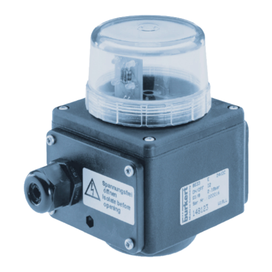
    ECHNISCHE ATEN Aufbau und Funktion Der MiniTOP Typ 8633 dient zur Ansteuerung pneumatisch betätigter Prozessventile. Er ist mit verschie- denen Ventiltypen aus dem Bürkert-Prozessventil-Programm kombinierbar (s. Datenblätter der Typen 2000, 2001, 2002, 2012, 2030, 2031, 2031K, 2652, 2655 und 2658). MiniTOP und Prozessventil sind durch einen Adapter miteinander verbunden.
  • Seite 37 ECHNISCHE ATEN Merkmale Ausführungen für einfach- oder doppeltwirkende Ventilantriebe Steuerventile nach dem Wippenprinzip arbeitendes Magnetventil 1 x 3/2-Wege-Steuerventil bei einfachwirkenden Ventilantrieben 2 x 3/2-Wege-Steuerventil bei doppeltwirkenden Ventilantrieben Elektrische Schnittstellen Metrische Kabelverschraubung mit Schraubklemmen Multipol-Rundsteckverbinder, 12polig (auf Anfrage) bei Busansteuerung (AS-Interface) werden die hierfür genormten 4poligen M12-Rund-Steckbinder oder metrischen Kabelverschraubungen mit Anschlussklemmen verwendet Pneumatische Schnittstellen 1/8’’-Anschlüsse in verschiedenen Gewindeformen (G, NPT, RC);...
  • Seite 38: Konformität

    ECHNISCHE ATEN Betriebsbedingungen Betriebstemperatur 0 ... + 55 °C Schutzart IP 65 nach EN 60529 Konformität CE-Zeichen konform bzgl. EMV-Richtlinie 89/336/EWG (nur bei korrekt angeschlossenem Kabel bzw. Stecker und Buchsen) Mechanische Daten Maße siehe Datenblatt Gehäusematerial MiniTOP außen PPE / PA, PSU; innen PA 6 Dichtungsmaterial MiniTOP Pneumatische Daten Steuermedium...
  • Seite 39: Elektrische Daten Ohne Busansteuerung

    ECHNISCHE ATEN Elektrische Daten ohne Busansteuerung Anschlüsse metrische Kabelverschraubung M16 mit Schraubklemmen Spannungsversorgung 24 V DC ± 10 % Restwelligkeit 10% bei induktiven Näherungsschaltern 110 V AC ± 10 %, 230 V AC ± 10 % Leistungsaufnahme Spannung einfachwirkend doppeltwirkend 24 V 110 V 230 V...
  • Seite 40 ECHNISCHE ATEN 38 - 8633...
  • Seite 41 NBETRIEBNAHME INBETRIEBNAHME Fluidische Installation ............................................Elektrische Installation ............................................8633 - 39...
  • Seite 42: Fluidische Installation

    NBETRIEBNAHME Fluidische Installation Die Abmessungen des MiniTOP und der verschiedenen Komplettgerätevarianten, bestehend aus MiniTOP, pneumatischem Antrieb und Ventil, entnehmen Sie den jeweiligen Datenblättern. Installation des Ventils Abmessungen und Gewindearten entnehmen Sie dem Datenblatt des Prozessventils. Montage des MiniTOP 8633 auf den Ventilantrieb Allgemeine Hinweise Die Montage des MiniTOP 8633 auf den Ventilantrieb und die Einstellung der Endschalterschaltpunkte geschieht bei diesem Gerät in einem Zuge und ist bei mechanischen und induktiven Endschaltern gleich.
  • Seite 43 NBETRIEBNAHME Versorgungsdruck 2-10bar Arbeitsanschluss 1 Arbeitsanschluss 2 (bei doppelt-wirkenden Antrieben) Gewindestift SW2 Klarsichtdeckel Signalteil Nocke oben (Kunststoffbund oben) Nocke unten (Kunststoffbund unten) O-Ring Messing-Führungsstück Kunststoffteil der Schaltspindel Kolbenstange Antrieb Antrieb Bild: Montage des MiniTOP Setzen Sie das MiniTOP-Gehäuse auf. Die Schaltspindel muss in die mittig liegende, von oben durch die Klarsichthaube sichtbare Bohrung des MiniTOP-Gehäuses geführt werden.
  • Seite 44: Einstellen Der Endschaltpunkte

    NBETRIEBNAHME Klemmen Sie den MiniTOP mit 2 Gewindestiften fest (Innensechskant SW2; Drehmoment zur Be- festigung 0,2 ... 0,4 Nm). Schrauben Sie die Schlauch-Steckverbindungen an den MiniTOP und den Ventilantrieb. Stellen Sie mit den im Zubehörsatz mitgelieferten Schläuchen die pneumatische Verbindung zwischen MiniTOP und Ventilantrieb her.
  • Seite 45: Fluidischer Anschluss Des Minitop

    NBETRIEBNAHME Gehen Sie dabei wie folgt vor: Trennen Sie das Gerät zuerst von der elektrischen und pneumatischen Versorgung! Lösen Sie die fluidische Verbindung zwischen dem MiniTOP und dem pneumatischen Antrieb. Lösen Sie die seitlich im Gehäuse versenkten Gewindestifte (Innensechskant SW2). Drehen Sie den MiniTOP ohne Anheben in die gewünschte Stellung.
  • Seite 46: Elektrische Installation

    NBETRIEBNAHME Elektrische Installation Die elektrische Kontaktierung des MiniTOP Typ 8633 wird über eine metrische Kabelverschraubung reali- siert. Für Geräte, die mit Schutzkleinspannung arbeiten (≤ 48 V), ist eine Ausführung mit Multipol-An- schluss in Vorbereitung. Anschlussklemmen für metrische Kabelverschraubungen HINWEIS Endschalter: wahlweise als Schließer (Klemmen NO) oder als Öffner (Klemmen NC) verwendbar.
  • Seite 47 NBETRIEBNAHME 24 V - Variante mit induktiven Näherungsschaltern (als Schließer) Klemme Belegung äußere Beschaltung Versorgung Initiatoren + 24 V +24 V DC (Restwelligkeit 10%) Versorgung Initiatoren GND Ausgang 1 (0V/24V) binärer Ausgang Initiator 1 (NO) Ausgang 2 (0V/24V) nicht belegt Bezug für Initator 1 GND binärer Ausgang Initiator 2 (NO) nicht belegt...
  • Seite 48 NBETRIEBNAHME 110 V - und 230 V - Variante mit mechanischen Endschaltern Klemme Belegung äußere Beschaltung Versorgung Endschalter Versorgung Endschalter NC1 (max. 5 A) Ausgang Endschalter 1 (NO) NO1 (max. 5 A) Ausgang Endschalter 1 (NC) NC2 (max. 5 A) NO2 (max.
  • Seite 49: Busansteuerung Über As-Interface

    NBETRIEBNAHME Busansteuerung über AS-Interface Standard Gerät Gerät für A/B-Slave Adressierung Zertifizierung: Zulassungs-Nr. 31902 (nach keine V.2.1) Programmierdaten: E/A-Konfiguration B hex (1 Ausgang, 2 Eingänge) ID-Code F hex (Belegung siehe unten) A hex (Belegung siehe unten) erweiterter ID-Code 1 F hex 7 hex erweiterter ID-Code 2 F hex...
  • Seite 50: Elektrischer Anschluss

    NBETRIEBNAHME (gelb) (gelb) Endschalter 1 betäigt Ventil mit Strom versorgt (Endstellung oben erreicht) (grün) (gelb) Statusanzeige LED1 ASI-Bus Endschalter 2 betäigt (rot) (Endstellung unten erreicht) Statusanzeige LED2 ASI-Bus Bild: Platine des MiniTOP, AS-Interface-Variante Elektrischer Anschluss 4poliger M12-Rund-Steckverbinder Pin 1: Bus + Pin 3: Bus - Metrische Kabelverschraubung mit Anschlussklemmen Öffnen Sie das Gehäuse...
  • Seite 51: Sicherheitsstellungen Und Wartung

    ICHERHEITSSTELLUNGEN UND ARTUNG SICHERHEITSSTELLUNGEN WARTUNG Sicherheitsstellungen nach Ausfall der elektrischen bzw. pneumatischen Hilfsenergie ................Wartung ................................................8633 - 49...
  • Seite 52 ICHERHEITSSTELLUNGEN UND ARTUNG Sicherheitsstellungen nach Ausfall der elektrischen bzw. pneumatischen Hilfsenergie Sicherheitseinstellungen nach Ausfall der Hilfsenergie Antriebsart Bezeichnung elektrisch pneumatisch einfachwirkend down down WW A down einfachwirkend WW B down doppeltwirkend down / up nicht definiert WW I (je nach Anschluss der Steuerleitungen) down Wartung...
  • Seite 53 ICHERHEITSSTELLUNGEN UND ARTUNG Notizen 8633 - 51...
  • Seite 54 ICHERHEITSSTELLUNGEN UND ARTUNG 52 - 8633...
  • Seite 55: Maintenance

    ABLE ATIERES Table des matieres des instructions de service de la MiniTOP 8633 INDICATIONS GENERALES ......................................Symboles graphiques ........................................Indications generales ........................................Volume de livraison ..........................................Clauses de garantie ..........................................CARACTERISTIQUES TECHNIQUES ................................Structure et fonction de la MiniTOP ................................Caractéristique de la construction MiniTOP ..........................
  • Seite 56 ABLE ATIERES 54 - 8633...
  • Seite 57: Indications Generales

    NDICATIONS ENERALES INDICATIONS GENERALES Moyens de representations ....................................Remarques generales ........................................Fourniture ................................................ Dispositions de garantie ......................................8633 - 55...
  • Seite 58: Remarques Generales

    NDICATIONS ENERALES Moyens de representations Les moyens de représentation suivants seront utilisés dans cette notice de service: marque un pas de travail que vous devrez faire ATTENTION! marque des instructions dont l’inobservation entraîne des dangers pour votre santé ou entrava la fonctionnalité de l’appareil. REMARQUE marque de informations additionnelles, conseils et recommandations.
  • Seite 59: Dispositions De Garantie

    NDICATIONS ENERALES Fourniture S’assurer immédiatement à la réception de l’envoi, que le contenu ne soit pas endommagé et qu’il concorde avec la fourniture indiquée sur bordereau joint à l’expédition. Généralement, celle-ci se compose: • du MiniTOP 8633 alternativement: • de la soupape de processus actionnée pneumatiquement des types 2000, 2001, 2002, 2012, 2030, 2031, 2031K, 2652, 2655, 2658.
  • Seite 60 NDICATIONS ENERALES 58 - 8633...
  • Seite 61: Caracteristiques Techniques

    ARACTERISTIQUES ECHNIQUES CARACTERISTIQUES TECHNIQUES Structure et fonctionnement du MiniTOP ............................Caractéristiques du MiniTOP ..................................... Conditions de service ........................................Conformité aux normes suivantes ................................Caractéristiques mécaniques .................................... Caractéristiques pneumatiques ..................................Caractéristiques électriques ....................................Caractéristiques électriques de la variante avec commande de bus (Inteface AS) ....
  • Seite 62 ARACTERISTIQUES ECHNIQUES Structure et fonctionnement du MiniTOP Le MiniTOP 8633 sert à commander des soupapes de processus pneumatiques. Il se combine avec divers types de soupapes de la gamme de soupapes de processus Bürkert (voir fiches techniques des types 2000, 2001, 2002, 2012, 20302031, 2031K, 2652, 2655 et 2658).
  • Seite 63 ARACTERISTIQUES ECHNIQUES Caractéristiques du MiniTOP type 8633 Versions pour commandes à simple ou double action des vannes Vannes pilotes Electrovanne travaillant selon le principe de bascule; Soupape de commande 1 x 3/2 voies en cas de mécanismes à effet simple Soupape de commande 2 x 3/2 voies en cas de mécanismes à...
  • Seite 64: Conditions De Service

    ARACTERISTIQUES ECHNIQUES Conditions de service Température de service 0 ... + 55 °C Proctection IP 65 selon EN 60529 Conformité aux normes suivantes Symbole CE conforme concernant directives CEM (seulement si câbles correctement branchés, resp. fiches et douilles) Caractéristiques mécaniques Dimensions Voir fiche technique Matière du boîtier MiniTOP...
  • Seite 65: Caractéristiques Électriques

    ARACTERISTIQUES ECHNIQUES Caractéristiques électriques Raccordement passe-câbles à vis métrique M 16 avec bornes à vis Tension d'alimentation 24 V DC ± 10 % Ondulation résiduelle 10% avec détecteurs de proximité indutifs 110 V AC ± 10 %, 230 V AC ± 10 % Puissance absorbée tension effet simple...
  • Seite 66 ARACTERISTIQUES ECHNIQUES 64 - 8633...
  • Seite 67: Installation

    NSTALLATION INSTALLATION Raccordement fluidique ..........................................Raccordement électrique ..........................................8633 - 65...
  • Seite 68: Installation De La Vanne

    NSTALLATION Raccordement fluidique Les dimensions du MiniTOP et les différentes variantes d'appareils complets comprenant MiniTOP, commande pneumatique et vanne, figurent sur les fiches techniques correspondantes. Installation de la vanne Dimensions et types de filetage se trouvent sour la fiche technique de la vanne de processus. Montage du MiniTOP 8633 sur la commande de la vanne Directives générales Le montage du MiniTOP sur la commande de la vanne et le réglage des points de commutation des fins...
  • Seite 69 NSTALLATION Pression d'alimentation 2 - 10 bar Raccord de travail 1 Raccord de travail 2 (avec commande à double action) Vis sans tête SW2 Partie Came en haut (Attache en signalisation plastique en haut) Couvercle transparent Came en bas (Attache en plastique en bas) Pièce de guidage Joint torique...
  • Seite 70 NSTALLATION Bloquer le MiniTOP avec 2 vis sans tête (SW2 à six pans creux; couple de serrage 0,2 ... 0,4 Nm). Vissez les connecteurs à fiche du tuyau souple au MiniTOP et à la commande de la vanne. Etablissez la liaison pneumatique entre le MiniTOP et la commande de la vanne à l’aide des tuyaux souples livrés dans le jeu d’accessoires.
  • Seite 71: Raccordement Des Fluides Du Minitop

    NSTALLATION Procédez à cet effet comme suit: Débrancher d’abord l’appareil des alimentations électrique et pneumatique! Desserrer la liaison des fluides entre le MiniTOP et la commande pneumatique. Desserrer les vis sans tête encastrées latéralement dans le boîtier (clé à six pans creux SW2). Faites pivoter le MiniTOP sans le soulever en bonne position.
  • Seite 72: Raccordement Électrique

    NSTALLATION Raccordement électrique Le contact électrique du MiniTOP type 8633 est réalisé par un passe-câble à vis métrique. Pour les appareils travaillant à basse tension de protection (≤ 48 V), une version à raccord multiple est en préparation. Bornes de raccordement pour passe-câbles à vis métrique REMARQUE Fin de course: utilisble au choix comme contact...
  • Seite 73 NSTALLATION Variante 24 V à détecteurs de procimité indutifs (comme contact de travail) Borne n° Occuptation Branchement extérieur Alimentation détecteurs de proximité + 24 V Alimentation détecteurs de proximité +24 V DC (Ondulation résiduelle 10%) Sortie 1 (0V/24V) Sortie binaire détecteur de proximité 1 (NO) Sortie 2 (0V/24V) non occupé...
  • Seite 74 NSTALLATION Variante 110 V et 230 V à fins de course mécaniques Borne n° Occupation Branchement extérieur Alimentation fin de course Alimentation fin de course NC1 (max. 5 A) Sortie fin de course 1 (NO) NO1 (max. 5 A) Sortie fin de course 1 (NC) NC2 (max.
  • Seite 75 NSTALLATION Commande de bus par interface AS Appareil standard Appareil pour A/B-Slave adressage Certification: Homologation n° 31902 (après pas de certification V.2.1) Données de programmation: Configuration E/A B hex (1 sortie, 2 entrées) ID Code F hex (occupation voir ci- A hex (occupation voir ci- dessous) dessous)
  • Seite 76 NSTALLATION (jaune) (jaune) Soupape alimentée en courant Fin de course 1 actionné (position finale en haut atteinte) (vert) Affichage d'état LED 1 bus ASI (jaune) Fin course 2 actionné (rouge) (psoition finale en bas Affichage d'état LED 2 bus ASI atteinte) Fig.: Platine du MiniTOP, variante interface AS Raccordement électrique...
  • Seite 77: Positions De Securite Et Maintenance

    OSITIONS DE SECURITE ET MAINTENANCE POSITIONS DE SECURITE MAINTENANCE Positions de sécurité après defaillance de l'energie auxilaire electrique ou pneumatique ..............Maintenance ..............................................8633 - 75...
  • Seite 78 OSITIONS DE SECURITE ET MAINTENANCE Positions de sécurité après defaillance de l'energie auxilaire electrique ou pneumatique Positions de sécurité après défaillance d'énergie auxiliaire Mode de service Désignation èlectrique pneumatique à effet simple WW A en bas en bas en haut en bas à...
  • Seite 79 Contact addresses / Kontaktadressen Germany / Deutschland / Allemange Bürkert Fluid Control System Sales Centre Chr.-Bürkert-Str. 13-17 D-74653 Ingelfingen Tel. + 49 (0) 7940 - 10 91 111 Fax + 49 (0) 7940 - 10 91 448 E-mail: info@de.buerkert.com International Contact addresses can be found on the internet at: Die Kontaktadressen finden Sie im Internet unter: Les adresses se trouvent sur internet sous :...
  • Seite 80 The smart choice of Fluid Control Systems www.buerkert.com...

Inhaltsverzeichnis