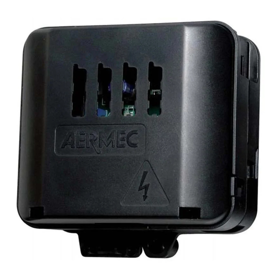
AERMEC VMF-E19 Bedienungsanleitung
Vmf-system erweiterbare thermostatplatine für gebläsekonvektoren
Vorschau ausblenden
Andere Handbücher für VMF-E19:
- Bedienungs- und installationsanleitung (28 Seiten)
Inhaltsverzeichnis
Verfügbare Sprachen
Verfügbare Sprachen
SISTEMA VMF SCHEDA TERMOSTATO ESPANDIBILE PER VENTILCONVETTORI
VMF SYSTEM EXPANDABLE THERMOSTAT BOARD FOR FAN COILS
SYSTÈME VMF PLATINE THERMOSTAT EXTENSIBLE POUR VENTILO-CONVECTEURS
VMF-SYSTEM ERWEITERBARE THERMOSTATPLATINE FÜR GEBLÄSEKONVEKTOREN
SISTEMA VMF TARJETA TERMOSTATO EXPANSIBLE PARA FAN COILS
VMF-E19
VMF-E19I
IT
GB
FR
DE
ES
AVMFE19LJ 2011 - 5779300_05
Inhaltsverzeichnis

Verwandte Anleitungen für AERMEC VMF-E19


Inhaltszusammenfassung für AERMEC VMF-E19
- Seite 1 SISTEMA VMF SCHEDA TERMOSTATO ESPANDIBILE PER VENTILCONVETTORI VMF SYSTEM EXPANDABLE THERMOSTAT BOARD FOR FAN COILS SYSTÈME VMF PLATINE THERMOSTAT EXTENSIBLE POUR VENTILO-CONVECTEURS VMF-SYSTEM ERWEITERBARE THERMOSTATPLATINE FÜR GEBLÄSEKONVEKTOREN SISTEMA VMF TARJETA TERMOSTATO EXPANSIBLE PARA FAN COILS VMF-E19 VMF-E19I AVMFE19LJ 2011 - 5779300_05...
-
Seite 2: Inhaltsverzeichnis
INDICE tipologie di impianto INHALT caratteristiche elettriche degli i/o art der anlage utilizzo del sistema elektrische eigenschaften der i/o comandi e visualizzazioni verwendung des systems logiche di controllo bedienelemente und anzeigen funzioni accessorie steuerlogiken controllo fancoil con piastra radiante zubehörfunktionen controlli aggiuntivi steuerung fancoil mit heizwand rete locale di fan coil... -
Seite 60: Art Der Anlage
ART DER ANLAGE LEGENDE: Raumtemperaturfühler Warm-/Kalt-Wassertemperaturfühler für 2 Rohre - Warm-Wassertemperaturfühler für 4 Rohre Kalt-Wassertemperaturfühler 4 Rohre. VS, VC, VF Magnetventil (Warm/Kalt), Warmwasserventil Kaltwasserventil V3, V2, V1 Maximale, durchschnittliche, minimale Geschwindigkeit des Ventilators Magnetventil zur Aktivierung der Heizwand 2 ROHRE 2 ROHRE MIT DREIWEGE-VENTIL 2 ROHRE MIT ZWEIWEGE-VENTIL Y2:Cold plasma... -
Seite 61: Rohre Mit Dreiwege-Ventilen
LEGENDE: Raumtemperaturfühler Warm-/Kalt-Wassertemperaturfühler für 2 Rohre - Warm-Wassertemperaturfühler für 4 Rohre Kalt-Wassertemperaturfühler 4 Rohre. VS, VC, VF Magnetventil (Warm/Kalt), Warmwasserventil Kaltwasserventil V3, V2, V1 Maximale, durchschnittliche, minimale Geschwindigkeit des Ventilators Magnetventil zur Aktivierung der Heizwand Y2:RE Y2:RE 2 ROHRE + ELEKTRISCHER WIDERSTAND 2 Tubi solo freddo + RE per il caldo 2 ROHRE NUR KÜHLBETRIEB + FÜR DIE WÄRME ALS ERSATZ/ERGÄNZUNG +... -
Seite 62: Elektrische Eigenschaften Der I/O
ELEKTRISCHE EIGENSCHAFTEN DER I/O FUNKTION ELEKTRISCHE EIGENSCHAFTEN Versorgungs-Klemmleiste Vin: 230 Vac, Imax: 5 A CN7-A Ausgang Steuerung Magnetventil Vout: 230 Vac, Imax: 0.7 A CN7-B Ausgang Steuerung Magnetventil Vout: 230 Vac, Imax: 0.7 A Ausgang für Motorsteuerung (gemeinsam) Vout: 230 Vac, Imax: 0.7 A Ausgang für Motorsteuerung (V3) Vout: 230 Vac, Imax: 0.7 A Ausgang für Motorsteuerung (V2) -
Seite 63: Bedienelemente Und Anzeigen
BEDIENELEMENTE UND ANZEIGEN Die Schnittstellen, die mit dem Thermostat VMF-E19 verbunden werden können, können Folgende sein: BENUTZERSCHNITTSTELLE VMF-E2 Geschwindigkeitswahlschalter; Temperaturwahlschalter Anzeigeleuchte des Betriebsmodus Anzeigeleuchte Lüftungsanfrage BENUTZERSCHNITTSTELLE VMF-E4X Taste ON/OFF Taste zum Ändern der Gebläsedrehzahl Tasten zum Ändern des Temperatursollwerts STEUERLOGIKEN Der Thermostat VMF-E19 kann Gebläsekonvektoren mit mehrstufigen Asynchronmotoren und Brushless-Motoren ausstatten. -
Seite 64: Durch Thermostat Gesteuerte Lüftung
THERMOSTATISIERUNG 0÷100 % Bei Gebläsekonvektoren mit Brushless-Motor gibt es ein Signalprofil von 0 -10 V, wie abgebildet: Einstellungsbereich Thermostatisierung 0÷100 % Toter Bereich Tamb [°C] Sollwert Warm Sollwert Kalt DURCH THERMOSTAT GESTEUERTE LÜFTUNG Die Wahl der Einstellung gemäß durch Thermostat gesteuerte Lüftung (Dip 3 OFF) sorgt dafür, dass die Lüftung bei Erreichen des eingestellten. -
Seite 65: Betrieb Ventil
BETRIEB VENTIL Bei Vorhandensein eines Absperrventils (DIP 1 ON) kann die Position des Temperaturfühlers sowohl vor als auch hinter dem Ventil (auf der Standardposition im Wärmetauscher) geregelt werden. Der wesentliche Unterschied zwischen den beiden besteht darin, die Lüftung auf verschiedene Weise zu steuern. Wenn sich der Wassertemperaturfühler vor dem Ventil befindet (DIP 2 ON) oder nicht vorhanden ist, ist eine Wärmetauscher-Vorwärmfunktion vorgesehen, um den Ventilator nach 2'40'' ab der ersten Öffnung des Ventils zu aktivieren. -
Seite 66: Wechselbetrieb Warm/Kalt Jahreszeitenwechsel Mit Wasser
Ventilsteuerlogik mit durch Thermostat gesteuerte Lüftung Ventilsteuerlogik mit kontinuierlicher Lüftung SOLLWERT WARM SOLLWERT KALT SET CALDO SET FREDDO SOLLWERT WARM SOLLWERT KALT SET CALDO SET FREDDO 100% 100% TOTER BEREICH ZONA MORTA TOTER BEREICH ZONA MORTA Y1: 2 Rohre Y1: 2 tubi Y1: 2/4 Rohre Y1: 2 Rohre Y1: 2/4 tubi... -
Seite 67: Zubehörfunktionen
Offen SLEEP-FUNKTION Die SLEEP-Funktion im Thermostat VMF-E19 ist verfügbar, wenn der Thermostat mit einem Vorhandensein-Sensor (mit normalerweise offener Logik) verbunden ist, der an seinen SP-Eingang angeschlossen ist. Die Funktion besteht in der Praxis darin, den Sollwert der Einstellung der Gebläsekonvektoren zu ändern, wenn der zu klimatisierende Raum nicht belegt ist;... -
Seite 68: Funktion Zubehörlasten Elektrischer Widerstand (Verwaltet Als Ergänzung)
DER NEUE SOLLWERT ZUR EINSTELLUNG WIRD UNTER BERÜCKSICHTIGUNG VON TABELLE 7 DURCH DIE FOLGENDE BEZIEHUNG GEGEBEN: SOLLWERT = EINGESTELLTER SOLLWERT Gleichung 1: Für Standalone-Thermostate SOLLWERT = GLOBALER SOLLWERT - ∆ Gleichung 2: Für Thermostate, die an ein BMS-System oder E5-Panel angeschlossen sind DER EINGANG IST GESPERRT, WENN DER THERMOSTAT AUFGRUND DES RAUMTEMPERATURFÜHLERS IM FROSTSCHUTZ- ODER NOTBETRIEB ARBEITET. -
Seite 69: Aktivierung Des Widerstands
Achtung: Auch wenn der Wassertemperaturfühler sich vor dem Ventil befindet, basiert der Wechsel der Jahreszeiten auf der Lufttemperatur. Bei dieser Konfiguration kann der Widerstand im Heizbetrieb zwei verschiedene Betriebsarten in Bezug darauf haben, wie der Betrieb des Thermostat gewählt wurde: BETRIEBSWEISE AKTIVIERUNG DES WIDERSTANDS AUTO... -
Seite 70: Steuerung Fancoil Mit Heizwand
STEUERUNG FANCOIL MIT HEIZWAND AUSWAHL DER STEUERUNG FANCOILS RADIANT DIP SWITCH SW2 ZUR AUSWAHL DER STEUERUNG DER HEIZWAND Um die Radiant-Gebläsekonvektoren zu steuern, muss die Einstellung der Heizwand mit den Dip Switchs SW2 (siehe Abbildung unten) ausgewählt werden. Die Funktionen dieser Dips sind in der Tabelle im Kapitel VERWENDUNG DES SYSTEMS beschrieben. THERMOSTAT MIT DREI EBENEN + HEIZWAND Die Abbildung unten zeigt den Betrieb des Ventilators im Automatikmodus (ausgewählter Betriebsmodus AUTO) entsprechend dem proportionalen Fehler. -
Seite 71: Betrieb Remote-Absperrventil
Wie in den Bildern in den Abbildungen zu sehen ist, ist die Lüftung in der Nähe des Sollwerts Warm deaktiviert und die Heizwand bleibt aktiv. Der Wert Δt kann von Dip 2 von SW2 eingestellt werden, wie in der Tabelle der Einstellung Dip-Switch SW2 angegeben ist. Der in der Abbildung gezeigte tote Bereich kann gleich 2°C oder 5°C sein, je nach durchgeführter Einstellung für Dip 7 BETRIEB REMOTE-ABSPERRVENTIL Bei Vorhandensein eines Remote-Absperrventils (Dip 1 ON) kann die Position des Wassertemperaturfühlers aus anlagentechnischen Gründen nur... -
Seite 72: Raumtemperaturfühler Fehlt (4 Rohre)
Raumtemperaturfühler fehlt (2 Rohre) In diesem Fall verhält sich der Thermostat wie folgt: ○ Wahlschalter in Position OFF - Aux • Das Ventil ist geschlossen • Der Ventilator ist ausgeschaltet ○ Wahlschalter in Position AUTO, V1, V2, V3: • Das Ventil ist immer offen. •... -
Seite 73: Lokales Netzwerk Des Fancoil
LOKALES NETZWERK DES FANCOIL NETZWERKSTRUKTUR Der Thermostat VMF-E19 wurde für die Kommunikation mit anderen Thermostaten der VMF-Familie über eine spezielle serielle Schnittstelle entwickelt, die auf logischen TTL-Standards und geringem Durchsatz basiert. Diese serielle Kommunikation ist wichtig für den Informationsaustausch innerhalb kleiner Fancoil-Netzwerke. Tatsächlich spricht man von einem Netzwerk von maximal 6 Thermostaten mit einer maximalen Länge von ca. -
Seite 74: Überwachungsnetzwerk An Rs485
Informationen bezüglich seines Betriebszustandes. Im Folgenden befindet sich die Liste der Variablen, die der Thermostat über die serielle Schnittstelle austauschen kann. HINWEIS: Der Thermostat VMF-E19 kann nur dann mit dem zentralisierten System kommunizieren, wenn er über eine Benutzerschnittstelle verfügt oder die Erweiterung VMF-IO aufweist. -
Seite 75: Steuerung Erweiterung Vmf-Io
STEUERUNG ERWEITERUNG VMF-IO Der Thermostat VMF-E19 kann mit der Erweiterung VMF-IO ausgestattet werden, die Folgendes beinhaltet: 2 digitale Ausgänge (Relaiskontakte 60Vdc 2A) 2 digitale Eingänge 8 Dip Switchs Dip Switch M1: Digitale Eingänge M2.1 und M2.2: Out1 M2.3 und M2.4: Out2... -
Seite 76: Steuerung Zur Überwachung Ohne Benutzerschnittstelle
Weitere Informationen zu den technischen Spezifikationen (physikalische Verbindung, ausgetauschte Daten, Systemeinstellungen) des LonWork-Protokolls befinden sich in der jeweiligen Dokumentation ÜBERWACHUNGSNETZWERK LONWORK Das am VMF-E19-Thermostat vorhandene System hat die Aufgabe, Informationen über die Funktionsweise des Systems zu geben: • Blinkt mit einer Frequenz von 1 Sekunde: Der Thermostat funktioniert regelmäßig •... -
Seite 77: Stromanschlüsse
STROMANSCHLÜSSE Nachstehend finden Sie wichtige Hinweise für qualifiziertem Personal kann zur Verletzung zuständigen technischen Kundendienst zu die richtige Installation der Geräte. von Personen und Geräteschäden bzw. kontaktieren. Es bleibt in jedem Fall der Erfahrung des Beschädigungen des Umfelds führen. • Außerhalb des Gebläsekonvektors Installateurs überlassen, alle Arbeitsvorgänge •... -
Seite 78: Anschlüsse An Die Platine
ANSCHLÜSSE AN DIE PLATINE • Für die Installation des Kits VMF-E19/E19I muss die serienmäßige Klemmleiste vom Gebläsekonvektor abgenommen werden. • Das Gehäuse des Thermostats an der Seitenwand des Gebläsekonvektors, an den Anschlüssen installieren, an denen vorher die Klemmleiste befestigt war. - Seite 98 COLLEGAMENTI • CONNECTIONS • RACCORDEMENTS • ANSCHLÜSSE • CONEXIONES Out 0-10V Rif.Inverter Out 0-10V In Fault Inverter Alimentazione motore ventilatore Fan motor power supply Alimentation du moteur du ventilateur Stromversorgung Ventilatormotor Alimentación motor ventilador Alimentazione elettrica Y1 Comando valvola VC/VF + Y2 Comando accessorio Power supply Y1 VC/VF control + Y2 Accessory control Alimentation électrique...
- Seite 99 COLLEGAMENTI • CONNECTIONS • RACCORDEMENTS • ANSCHLÜSSE • CONEXIONES SP Sensore presenza + CE Contatto esterno Sonda temperatura aria SP Presence sensor + CE External contact Air probe SP Capteur de présence + CE Contact extérieur Sonde d’air SP Anwesenheitssensor + CE Außenkontakt Lufttemperaturfühler SP Sensor de presencia + CE Contacto externo Sonda aire...
- Seite 100 RS485 - COLLEGAMENTI • CONNECTIONS • RACCORDEMENTS • ANSCHLÜSSE • CONEXIONES Seriale supervisione RS485 (VMF_E19 - VMF_E19) Supervision serial RS485 (VMF_E19 - VMF_E19) Liaison série de supervision RS485 (VMF_E19 - VMF_E19) Serielle Überwachungsschnittstelle RS485 (VMF_E19 - VMF_E19) Serial supervisión RS485 (VMF_E19 - VMF_E19) 22AWG-3 22AWG-3 22AWG-3...
-
Seite 101: Schemi Elettrici • Wiring Diagrams • Schemas Electriques • Schaltpläne • Esquemas Eléctricos
SCHEMI ELETTRICI • WIRING DIAGRAMS • SCHEMAS ELECTRIQUES • SCHALTPLÄNE • ESQUEMAS ELÉCTRICOS VMF-E19 G l i s c h e m i e l ett r i c i s o n o s o g gett i a d u n co nt i n u o a g g i o r n a m e nto, è o b b l i gato r i o q u i n d i fa re r i fe r i m e nto a q u e l l i a b o rd o m a c c h i n a . -
Seite 102: Schemi Elettrici • Wiring Diagrams • Schemas Electriques • Schaltpläne • Esquemas Eléctricos
SCHEMI ELETTRICI • WIRING DIAGRAMS • SCHEMAS ELECTRIQUES • SCHALTPLÄNE • ESQUEMAS ELÉCTRICOS VMF-E19I G l i s c h e m i e l ett r i c i s o n o s o g gett i a d u n co nt i n u o a g g i o r n a m e nto, è o b b l i gato r i o q u i n d i fa re r i fe r i m e nto a q u e l l i a b o rd o m a c c h i n a . A l l w i r i n g d i a g r a m s... - Seite 103 AERMEC S.p.A. si riserva la facoltà di apportare in qualsiasi momento tutte le modifiche ritenute necessarie per il miglioramento del prodotto. Les données mentionnées dans ce manuel ne constituent aucun engagement de notre part. Aermec S.p.A. se réserve le droit de modifier à tous moments les données considérées nécessaires à...