Herunterladen Diese Seite drucken
PR electronics 2224 Anleitung
Vorschau ausblenden Andere Handbücher für 2224:

Werbung

Verfügbare Sprachen

Verfügbare Sprachen

Isolation
Galvanic isolators for analogue and digital
signals as well as HART
®
signals. A wide product range
with both loop-powered and universal isolators featuring
linearisation, inversion, and scaling of output signals.
Displays
Programmable displays with a wide se-
lection of inputs and outputs for display of temperature,
volume, weight, etc. Feature linearisation, scaling, and
difference measurement functions for programming via
PReset software.
Ex barriers
Interfaces for analogue and digital signals
as well as HART
®
signals between sensors / I/P convert-
ers / frequency signals and control systems in Ex zone 0,
1 & 2. Feature options such as mathematical functions
and 2 wire transmitter interfaces.
Temperature
A wide selection of transmitters for DIN
form B mounting and DIN rail modules with analogue
and digital bus communication ranging from application-
specifi c to universal transmitters.
Backplane
Flexible motherboard solutions for sys-
tem 5000 modules. Our backplane range features fl exible
8 and 16 module solutions with confi guration via PReplan
8470 – a PC program with drop-down menus.
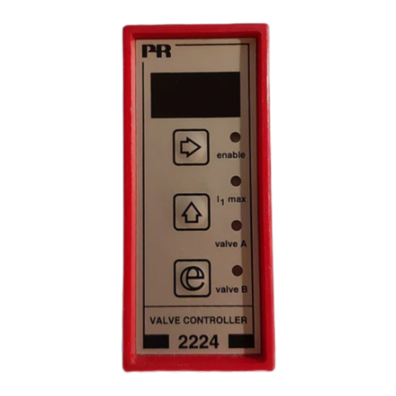
2 2 2 4
V a l v e C o n t r o l l e r
N o . 2 2 2 4 V 1 0 1 - I N ( 0 2 4 2 )
F r o m s e r . n o . 0 1 0 3 5 2 0 0 1
S I G N A L S T H E B E S T
Side 1
DK
Page 19
UK
Page 37
FR
Seite 55
DE

Werbung

loading

Inhaltszusammenfassung für PR electronics 2224

  • Seite 1 Isolation Galvanic isolators for analogue and digital signals as well as HART ® signals. A wide product range with both loop-powered and universal isolators featuring linearisation, inversion, and scaling of output signals. Displays Programmable displays with a wide se- lection of inputs and outputs for display of temperature, volume, weight, etc.
  • Seite 2: Inhaltsverzeichnis

    VENTILSTYRING Type 2224 Indholdsfortegnelse Overensstemmelseserklæring ..........Adskillelse af SYSTEM 2200..........Anvendelse................Teknisk karakteristik ............Indgang ................Udgang................Bestillingsskema ..............Elektriske specifikationer ............ Blokdiagram ................ Timing diagram ..............DIP-switchprogrammering ..........Fortrådningsdiagrammer for joystick / potentiometerindgang ............ 10 Fortrådningsdiagrammer for DC strømindgang....11 Fortrådningsdiagrammer for DC spændingsindgang ..
  • Seite 3: Overensstemmelseserklæring

    OVERENSSTEMMELSESERKLÆRING ADSKILLELSE AF SYSTEM 2200 Som producent erklærer Billede 1. PR electronics A/S Modulets bagplade frigøres fra huset ved hjælp af en skruetrækker. Lerbakken 10 DK-8410 Rønde hermed at følgende produkt: Type: 2224 Navn: Ventilstyring Fra serienr.: 940963 ff er i overensstemmelse med følgende direktiver og standarder: EMC-direktivet 89/336/EEC og senere tilføjelser...
  • Seite 4: Anvendelse

    • Er yderst velegnet til joystick-regulering af A/B bevægelse. Teknisk karakteristik: • Ventilstyringen 2224 er en mikroprocessor-styret enhed, som indeholder ram- pefunktioner til blød start og stop og springfunktioner således, at dødbånd undgås ved start og ved skift mellem A & B ventil.
  • Seite 5: Indgang

    Elektriske specifikationer: Blokdiagram: Specifikationsområde: (@: -20°C til +60°C) Fælles specifikationer: Forsyningsspænding ........12 eller 24 VDC ±20% Egetforbrug..........2 W / 24 V 1,8 W / 12 V Kommunikation..........Frontprogrammering Opdateringstid..........30 ms Temperaturkoefficient ........0,01% / °C Linearitetsfejl ..........0,2% EMC-immunitetspåvirkning ......
  • Seite 6: Timing Diagram

    Timing-diagram: DIP-switchprogrammering: Med DIP-switchindstillingen vælges både indgangssignalet og funktionen. Funktion 1: Enkelt- og dobbelt ventilstyring. Ved dobbelt ventilstyring vælges A ventil ved at påtrykke +Vforsyning på terminal 2. Funktion 2: Dobbelt ventilstyring med automatisk skift mellem A og B ventil (intet signal på terminal 2).
  • Seite 7: Fortrådningsdiagrammer For Joystick / Potentiometerindgang

    Fortrådningsdiagrammer for joystick- / potentiometerindgang Fortrådningsdiagrammer for DC strømindgang Dobbelt ventilstyring via +/- Dobbelt ventilstyring med 10 VDC referencespænding. 0...20 mA indgangssignal. DIP-switchprogrammering: DIP-switchprogrammering: Funktion 2. Funktion 1 eller Funktion 2. Dobblet ventilstyring via + 10 VDC referencespænding. DIP-switchprogrammering: Funktion 1 eller Funktion 2.
  • Seite 8: Fortrådningsdiagrammer For Dc Spændingsindgang

    Fortrådningsdiagrammer for DC spændingsindgang Teknisk beskrivelse: • For at hindre at programmering kan ske under drift, er der indlagt to sikker- Dobbelt ventilstyring med hedsforanstaltninger. Det korrekte password (030) skal indtastes i menuen 0...1 VDC indgangssignal. DIP-switchprogrammering: [PAS], og udgangen må ikke give signal (displayet skal vise 000). Dette opnås Funktion 1 eller ved at afbryde +Vforsyning på...
  • Seite 10: Rutediagram

    PROGRAMMERING / BETJENING 0.0. Normal tilstand - displayet viser udgangsværdi i procent af I ventil . Displayet går til denne tilstand ved power ON, eller hvis ingen taster har AF TRYKKNAPPER været aktiveret i en periode på 2 minutter. 1.0 VAL - Indtastning af password. 1.1 PAS - Programmeringsadgang.
  • Seite 11 Technical characteristics ............. 22 6.0 PRO - Produktion. Input ..................23 OBS! Værdier må ikke ændres! Output ................. 23 Hovedmenu med undermenuer, som PR electronics A/S anvender til Order ................... 23 opsætning og kalibrering af 2224. Electrical specifications............24 Block diagram ..............25 Timing diagram ..............
  • Seite 12: Declaration Of Conformity

    DECLARATION OF CONFORMITY HOW TO DISMANTLE SYSTEM 2200 As manufacturer Picture 1. PR electronics A/S The back panel of the module is detached from the housing by way Lerbakken 10 of a screwdriver. DK-8410 Rønde hereby declares that the following product:...
  • Seite 13: Applications

    • Is highly suitable for joystick regulation of A/B movements. Technical characteristics: • The 2224 Valve Controller is a microprocessor-based unit containing ramp functions for soft start and stop and jump functions thus avoiding deadband at start and changes between A & B valves.
  • Seite 14: Electrical Specifications

    Electrical specifications: Block diagram: Specifications range: (@: -20°C to +60°C) Common specifications: Supply voltage..........12 or 24 VDC ±20% Internal consumption........2 W / 24 V 1.8 W / 12 V Communication ........... Front-programmable Updating time ..........30 ms Temperature coefficient ....... 0.01%/°C Linearity error..........
  • Seite 15: Timing Diagram

    Timing diagram: Dipswitch programming: Input signal and function are chosen via the dipswitch setting. Function 1: Single and double valve control. By double valve control, A valve is chosen by applying +Vsupply to terminal 2. Function 2: Double valve control with automatic change between A and B valves (no signal on terminal 2).
  • Seite 16: Wiring Diagrams For Joystick / Potentiometer Input

    Wiring diagrams for joystick / potentiometer input Wiring diagrams for DC current input Double valve control (A/B Double valve control (A/B valves) from +/-10 VDC refe- valves) from a 4...20 mA input rence supply. signal. Dipswitch programming: Dipswitch programming: Function 2. Function 1 or Function 2.
  • Seite 17: Wiring Diagrams For Dc Voltage Input

    Function 1 or Function 2. • The 2224 Valve Controller can be controlled by a joystick / potentiometer using the internal +10 V and -10 V supply, or a process current / voltage sig- nal. For process signals the differential amplifier (DP1 switch 6 off) will pre- vent potential electrical error due to improper grounding.
  • Seite 19: Routing Diagram

    PROGRAMMING / OPERATING 0.0. DEFAULT - Output percentage value of I is displayed. valve At power ON, or if no keys have been activated for a period of 2 minutes, THE FUNCTION KEYS the display returns to default. 1.0 VAL - Enter password. DOCUMENTATION FOR ROUTING DIAGRAM 1.1 PAS - Programming access.
  • Seite 20 6.0 PRO - Production. Entrée .................. 41 NB! The factory settings must not be changed. Sortie ................... 41 Main menu with submenus that PR electronics A/S use for the set-up Commande................41 and calibration of the 2224 Valve Controller. Spécifications électriques ........... 42 Schéma de principe ............
  • Seite 21: Déclaration De Conformité

    Lerbakken 10 DK-8410 Rønde déclare que le produit suivant : Type : 2224 Nom : Regulateur de vanne A partir du no. de série : 940963 sqq. correspond aux directives et normes suivantes : Figure 2.
  • Seite 22: Applications

    • Les circuits de mesure et régulation interne assurent au courant moyen de ne pas excéder la valeur entrée : Ivanne. • Le régulateur de vanne 2224 est idéal pour la régulation de mouvements A/B par manettes potentiométriques. • Si le courant de pointe excède 7A, la sortie sera désactivée.
  • Seite 23: Spécifications Électriques

    Spécifications électriques : Schéma de principe : Plage des spécifications : (@ : -20°C à +60°C) Spécifications communes : Tension d’alimentation......... 12 ou 24 Vcc ±20% Consommation interne ........ 2 W / 24 V 1,8 W / 12 V Configuration ..........Programmable en face avant Temps de réponse........
  • Seite 24: Diagramme De Fonctionnement

    Diagramme de fonctionnement : Configuration des commutateurs : Le signal d'entrée et les fonctions sont choisis à l'aide de commutateurs. Fonction 1 : Contôle de vanne simple ou double. Dans le cas de contrôle d'une vanne double, la vanne A est choisie en raccordant le +de la tension d'alimentation à la borne 2. Fonction 2 : Contrôle de vanne double avec changement automatique entre les vannes A et B (pas de signal sur la borne 2).
  • Seite 25 Diagrammes de raccordement pour entrée manette / Diagrammes de raccordement pour l’entrée courant cc potentiomètre Contrôle double par un signal Contrôle double par tension d’entrée de 4...20 mA. de référence de +/-10 Vcc. Configuration des commu- Configuration des commu- tateurs : tateurs : Fonction 1 ou Fonction 2.
  • Seite 26: Description Technique

    Fonction 1 ou Fonction 2. • Le PR-2224 peut être contrôlé par une manette / un potentiomètre en utili- sant l’alimentation interne de +10 V ou ±10 V, ou un signal courant / tension. Pour les signaux de contrôle, l’entrée peut être connectée comme un amplifi- cateur différentiel (DP1 switch 6 off) et ainsi neutraliser des erreurs électriques...
  • Seite 28: Diagramme De Programmation

    PROGRAMMATION / UTILISATION 0.0. Mise sous tension - La valeur de la I vanne . L’affichage prend cet état lors de la mise sous tension ou si aucune touche DES TOUCHES DE FONCTION n’est actionnée pendant deux minutes. 1.0 VAL - Accès à la programmation. DOCUMENTATION POUR LE DIAGRAMME DE PROGRAMMATION 1.1 PAS - Accès à...
  • Seite 29: Ventilsteuerung

    6.0 PRO - Production. Eingang ................59 NB ! Vous ne devez pas modifier ces valeurs ! Ausgang ................59 Le menu principal avec les sous-menus qu’utilise PR electronics A/S Bestellangaben..............59 pour la programmation et configuration de PR-2224. Elektrische Daten ..............60 Blockdiagramm ..............
  • Seite 30: Konformitätserklärung

    KONFORMITÄTSERKLÄRUNG ZERLEGUNG DES SYSTEMS 2200 Als Hersteller bescheinigt Abbildung 1. PR electronics A/S Die hintere Abdeckplatte des Moduls wird vom Gehäuse mit Hilfe Lerbakken 10 eines Schraubendrehers gelöst. DK-8410 Rønde hiermit für das folgende Produkt: Typ: 2224 Name: Ventilsteuerung Ab der Serien-Nr.: 940963 ff.
  • Seite 31: Anwendung

    Technische Merkmale: • Der interne Meß- und Regelkreislauf sichert, das der Mittelstrom nie den ein- • Die Ventilsteuerung 2224 ist eine mikroprozessorgesteuerte Einheit, die getasteten Wert des I Ventils übersteigt. Rampenfunktionen für einen weichen Start und Stopp enthält, weiterhin •...
  • Seite 32: Elektrische Daten

    Elektrische Daten: Blockdiagramm: Spezifikationsbereich: (@-20°C bis +60°C) Gemeinsame Daten: Versorgungsspannung......... 12 oder 24 VDC ±20% Eigenverbrauch..........2 W / 24 V 1,8 W / 12 V Kommunikation..........Frontprogrammierung Aufdatierungszeit......... 30 ms. Temperaturkoeffizient ........0,01% / °C Linearitätsfehler ........... 0,2% Immunitätseinwirkung ......... < 2% d. Meßspanne Relative Luftfeuchtigkeit ......
  • Seite 33: Zeitdiagramm

    Zeitdiagramm: DIP-Schalterprogrammierung: Eingangssignal und Funktionen werden über DIP-Schalter gewählt. Funktion 1: Einfach- und Doppelventilsteuerung. Bei Doppenventilsteuerung wird das Ventil A durch Anlegen der +UB Versorgung an Klemme 2 angewählt. Funktion 2: Doppelventilsteuerung mit automatischem Wechsel zwischen Ventil A und B (kein Signal an Klemme 2) Eingangssignal: 0...50 % = Ventil A 100...0% Eingangssignal: 50...100 % = Ventil B 0...100%...
  • Seite 34: Verdrahtungsdiagramme Für Joystick/Potentiometereingang

    Verdrahtungsdiagramme für Joystick- / Potentiometereingang Verdrahtungsdiagramme für DC-Stromeingang Zweifache Ventilsteuerung Zweifache Ventilsteuerung durch eine +/- 10 VDC mit einem 4...20 mA Referenzspannung Eingangssignal. DIP-Schalterprogrammierung: DIP-Schalterprogrammierung: Funktion 2. Funktion 1 oder Funktion 2. Zweifache Ventilsteuerung durch eine + 10 VDC Referenzspannung. DIP-Schalterprogrammierung: Funktion 1 oder Funktion 2.
  • Seite 35: Verdrahtungsdiagramme Für Dc Spannungseingang

    Verdrahtungsdiagramme für DC-Spannungseingang Technische Beschreibung: • Zwei Sicherheitsmaßnahmen sind eingelegen um Programmierung während Zweifache Ventilsteuerung des Betriebs zu verhindern. Das korrekte Passwort (030) muß ins Menü [PAS] mit einem Eingangssignal von eingegeben werden und der Ausgang muß kein Signal abgeben (das Display 0...1 VDC.
  • Seite 37: Programmierung / Bedienung Der Drucktasten

    PROGRAMMIERUNG / BEDIENUNG VAL - Eintasten des Paßwortes. 1.1 PAS - Programmierzutritt. DER DRUCKTASTEN Das akzeptierte Passwort gilt bis die Versorgungsspannung abgeschal- tet ist. DOKUMENTATION ZUM SCHLEIFENDIAGRAMM Das Passwort ist 030 Allgemeines: 2.0 CUA - Einstellung der Ströme für Ventil A. Die Programmierung ist menügesteuert.
  • Seite 38 Die Einstellung geschieht in Ampère - mit 2 Dezimalen. Zulässige Wahlmöglichkeiten 0...3,00 A. 6.0 PRO - Produktion. OBS -Die Werte müssen nicht geändert werden! Das Hauptmenü mit den Untermenüs das PR electronics A/S zum Aufsetzen und Kalibrieren von 2224 anwendet.
  • Seite 39 Head offi ce PR electronics A/S tilbyder et bredt program af analoge og di- Denmark www.prelectronics.com gitale signalbehandlingsmoduler til industriel automation. Vores PR electronics A/S sales@prelectronics.dk Lerbakken 10 tel. +45 86 37 26 77 kompetenceområder omfatter: Isolation, Displays, Ex-barrierer, DK-8410 Rønde fax +45 86 37 30 85 Temperatur samt Backplanes.