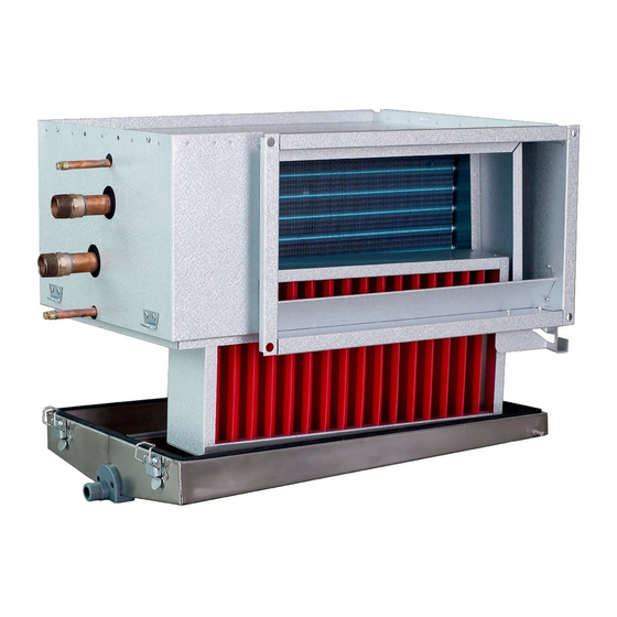
SystemAir PGK Bedienungsanleitung
Kanalkühlregister für külwasser zum einbau in rechteckige lüftungskanäle
Verfügbare Sprachen
Verfügbare Sprachen
Quicklinks
PGK
Manual
SE
Kanalkylare för kylvatten för montering i rektangulära ventilationskanaler.
VIKTIGT: Läs denna manual innan produkten monteras och ansluts och tas i bruk.
Spara anvisningen för framtida bruk.
........................................................................................................................................................................2
Manual
GB
Duct cooler for cold water for mounting in rectangular ventilation ducts.
IMPORTANT: Read this manual before installing, connecting and using the product.
........................................................................................................................................................................4
Handbuch
DE
Kanalkühlregister für külwasser Zum Einbau in rechteckige Lüftungskanäle.
ACHTUNG: Lesen Sie diese Anleitung vor Montage, Anschluss und Inbetriebnahme des
Produktes sorfältig durch.
Die Gebrauchsanweisung für zukünftigen Gebrauch aufbewahren
.........................................................................................................................................................................6
Save the instructions for future use.
Art.nr. 172391-04

Verwandte Anleitungen für SystemAir PGK


Inhaltszusammenfassung für SystemAir PGK
- Seite 1 Manual Kanalkylare för kylvatten för montering i rektangulära ventilationskanaler. VIKTIGT: Läs denna manual innan produkten monteras och ansluts och tas i bruk. Spara anvisningen för framtida bruk..................................2 Manual Duct cooler for cold water for mounting in rectangular ventilation ducts. IMPORTANT: Read this manual before installing, connecting and using the product.
- Seite 6 Montage Wasseranschluß Der Kanalkühler PGK ist vorgesehen für Kühlwasser als Kühl- Betriebsdaten: Max. Betriebstemperatur/Betriebsdruck medium. Das Kühlregister besteht aus Kupferrohren und Lamel- 100°C/1,0 MPa. (10 Bar) len aus Aluminium. Das Kühlregister darf nicht für eine direkte Bei Anschluß eines Kanalkühlers an das Rohrsystem muß fol- Expansion des Kühlmediums ausgesetzt werden.
- Seite 7 Abb. 2 Abb. 3 Abb. 4 Abb. 5 Entfernen Sie den Tropfbehälter, indem Sie zuerst die Exzen- Tropfenabscheider terverschlüsse an der Vorderseite öffnen. Senken Sie den Tropf- Der Tropfenabscheider DE wird nach dem Kühlregister im behälter dann ca. 2 – 3 cm ab und schieben Sie ihn nach hinten, Kanalkühler in Luftrichtung gesehen eingebaut.