Ducati Performance 96481182A Montageanleitung
ISTR - 819 / 01
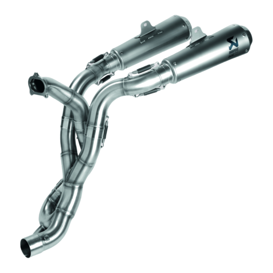
Kit scarico completo Racing - 96481182A
Racing complete exhaust system kit - 96481182A
Simbologia
Per una lettura rapida e razionale sono stati impiegati simboli che
evidenziano situazioni di massima attenzione, consigli pratici o
semplici informazioni. Prestare molta attenzione al significato dei
simboli, in quanto la loro funzione è quella di non dovere ripete-
re concetti tecnici o avvertenze di sicurezza. Sono da considerare,
quindi, dei veri e propri "promemoria". Consultare questa pagina
ogni volta che sorgeranno dubbi sul loro significato.
Attenzione
La non osservanza delle istruzioni riportate può creare una situa-
zione di pericolo e causare gravi lesioni personali e anche la morte.
Importante
Indica la possibilità di arrecare danno al veicolo e/o ai suoi compo-
nenti se le istruzioni riportate non vengono eseguite.
Note
Fornisce utili informazioni sull'operazione in corso.
Riferimenti
I particolari evidenziati in grigio e riferimento numerico (Es.
rappresentano l'accessorio da installare e gli eventuali componenti
di montaggio forniti a kit.
I particolari con riferimento alfabetico (Es.
componenti originali presenti sul motoveicolo.
Tutte le indicazioni destro o sinistro si riferiscono al senso di marcia
del motociclo.
Avvertenze generali
Attenzione
Le operazioni riportate nelle pagine seguenti devono essere ese-
guite da un tecnico specializzato o da un'officina autorizzata Du-
cati.
Attenzione
Le operazioni riportate nelle pagine seguenti se non eseguite a re-
gola d'arte possono pregiudicare la sicurezza del pilota.
Note
Documentazione necessaria per eseguire il montaggio del Kit è il
Manuale Officina, relativo al modello di moto in vostro possesso.
Note
Nel caso fosse necessaria la sostituzione di un componente del kit
consultare la tavola ricambi allegata.
1
Symbols
The symbols used in this manual are aimed at making reading di-
rect and easy. The symbols are used either to draw the reader's
attention on potentially hazardous conditions, or to give practical
advice or to supply general information. Pay the utmost attention
to these symbols as they are used to remind of technical principles
or safety measures which will not be repeated extensively. They
must therefore be considered as "reminders". Check with this page
in case of doubt about their meaning.
Failure to comply with these instructions may put you at risk and
lead to severe injury or death.
It indicates the possibility of damaging the motorcycle and/or its
components if the instructions are not followed.
It supplies useful information about the operation in progress.
References
1
)
The parts highlighted in grey and with a reference number (e.g.
) represent the accessory to be installed and any assembly compo-
nents supplied with the kit.
A
) rappresentano i
The parts with alphabetic reference (e.g.
components present on the motorcycle.
All left and right indications are referred to the motorcycle direc-
tion of travel (forward riding position).
General notes
The operations listed in the following pages must be carried out by
a specialised technician or by a Ducati authorised service centre.
Carefully perform the operations on the following pages since they
might negatively affect rider safety.
The Workshop Manual of your motorcycle model is the documen-
tation required to assemble the Kit.
Should it be necessary to change any kit parts, please refer to the
attached spare part table.
Operating, servicing and maintaining a passenger vehicle or off-
highway motor vehicle can expose you to chemicals including en-
gine exhaust, carbon monoxide, phthalates, and lead, which are
known to the State of California to cause cancer and birth defects
or other reproductive harm. To minimize exposure, avoid breath-
ing exhaust, do not idle the engine except as necessary, service
your vehicle in a well-ventilated area and wear gloves or wash your
hands frequently when servicing your vehicle. For more informa-
tion go to www.P65Warnings.ca.gov/passenger-vehicle.
Warning
Important
Notes
Warning
Warning
Notes
Notes
Warning
1
A
) represent the original
Inhaltsverzeichnis

Verwandte Anleitungen für Ducati Performance 96481182A


Inhaltszusammenfassung für Ducati Performance 96481182A
- Seite 1 Du- The operations listed in the following pages must be carried out by cati. a specialised technician or by a Ducati authorised service centre. Attenzione Warning Le operazioni riportate nelle pagine seguenti se non eseguite a re- Carefully perform the operations on the following pages since they gola d’arte possono pregiudicare la sicurezza del pilota.
- Seite 2 ISTR 819 / 01...
- Seite 3 ISTR 819 / 01 Importante Important I componenti del kit possono essere soggetti ad aggiornamenti; The parts of the kit can be updated; for information always up to consultare il DCS (Dealer Communication System) per avere infor- date, please refer to DCS (Dealer Communication System). mazioni sempre aggiornate.
- Seite 4 ISTR 819 / 01 Smontaggio componenti originali Removing the original components Attenzione Warning Il motore e le parti del sistema di scarico diventano molto calde Engine and exhaust system parts become hot when using the con l'uso della motocicletta, e rimangono calde ancora per lungo motorcycle, and remain hot for a long time after the engine has tempo dopo aver fatto funzionare il motore.
- Seite 5 ISTR 819 / 01 Smontaggio convogliatore sinistro Removing LH conveyor Svitare e recuperare le viti (B1) e (B2). Traslare il convogliatore Loosen and collect screws (B1) and (B2). Shift the LH conveyor (B) sinistro (B) verso la parte posteriore del motoveicolo e sollevare towards the rear side of the motorcycle and lift it up after releasing verso l’alto sganciando le n.2 linguette (B3) dalle asole (D1) del the 2 tabs (B3) from slots (D1) of the front subframe (D) and the 2...
- Seite 6 ISTR 819 / 01 Smontaggio convogliatore destro Removing RH conveyor Svitare e recuperare le viti (F1) e (F2). Traslare il convogliatore Loosen and collect screws (F1) and (F2). Shift the RH conveyor (F) destro (F) verso la parte posteriore del motoveicolo e sollevare towards the rear of the motorcycle and lift it up after releasing the verso l’alto sganciando le n.2 linguette (F3) dalle asole (D2) del 2 tabs (F3) from slots (D2) of the front subframe (D) and the 2 tabs...
- Seite 7 ISTR 819 / 01 Smontaggio cover blocco chiave Removing the ignition switch cover Svitare i n.2 dadi speciali (G1) di fissaggio della cover blocco chiave Loosen no.2 special nuts (G1) fastening ignition switch cover (G). (G). Rimuovere la cover blocco chiave (G). Remove ignition switch cover (G).
- Seite 8 ISTR 819 / 01...
- Seite 9 ISTR 819 / 01 Smontaggio carena sinistra Removing the LH fairing Operando sul lato sinistro del motoveicolo, svincolare il tubo sfiato Working on the motorcycle left side, release the breather pipe (H) (H) dalla sede (C2) posta sulla parte inferiore della carena sinistra from its seat (C2) on the lower side of the LH fairing (C).
- Seite 10 ISTR 819 / 01...
- Seite 11 ISTR 819 / 01 Smontaggio carena destra Removing the RH fairing Operando sul lato destro del motoveicolo, svitare la vite (E5) con Working on the RH side of the motorcycle, loosen the screw (E5) distanziale con collare (E6) di fissaggio alla staffa inferiore di with spacer with collar (E6) retaining the fairing support lower sostegno carena.
- Seite 12 ISTR 819 / 01...
- Seite 13 ISTR 819 / 01 Smontaggio serbatoio Removing the tank Operando da entrambi i lati del motoveicolo, svitare le n.2 viti (M1) Working from both sides of the motorcycle, loosen the 2 screws e svincolare i pioli (M2) posti sulla parte anteriore dei n.2 fianchetti (M1) and release the pins (M2) placed on the front part of the 2 (M) dai gommini antivibranti (L3), come mostrato nel riquadro (X), side panels (M) from vibration dampers (L3), as shown in the box...
- Seite 14 ISTR 819 / 01 Smontaggio filtro Removing the filter Rimuovere la fascetta a strappo (N1). Svitare le n.3 viti (N2) e Remove the self-locking tie (N1). Loosen no.3 screws (N2) and rimuovere il filtro (N). Recuperare le n.3 viti (N2). remove the filter (N).
- Seite 15 ISTR 819 / 01 Smontaggio motorino valvola di scarico Removing the exhaust valve motor Scalzare il cablaggio motorino valvola di scarico dal supporto Pry the exhaust valve motor wiring from the connector support connettori (P1). Scollegare il connettore motorino valvola di scarico (P1).
- Seite 16 ISTR 819 / 01 Smontaggio paracalore motorino valvola di scarico Removing the exhaust valve motor heat guard Svitare la vite (P7) e rimuovere il paracalore motorino valvola di Loosen the screw (P7) and remove the exhaust valve motor heat scarico (P6). guard (P6).
- Seite 17 ISTR 819 / 01 Smontaggio gruppo silenziatore Removing the silencer unit Rimuovere le n.2 fascette a bottone (Q1) e le n.4 fascette a strappo Remove the 2 button ties (Q1) and the 4 large self-locking ties grandi (Q12). Scollegare il cablaggio sonda lambda verticale (Q2) (Q12).
- Seite 18 ISTR 819 / 01...
- Seite 19 ISTR 819 / 01 Operando sul lato sinistro del motoveicolo, svitare le n.2 viti (Q3) Working on vehicle LH side, loosen 2 screws (Q3) with 2 washers con n.2 rosette (Q4). Rimuovere il paracalore sinistro (Q5), le n.2 (Q4). Remove LH heat guard (Q5), no.2 washers (Q4) and no.2 rosette (Q4) e i n.2 distanziali con collare (Q6).
- Seite 20 ISTR 819 / 01...
- Seite 21 ISTR 819 / 01 Operando sul lato destro del motoveicolo, svitare la vite (V1) e Working on the RH side of the motorcycle, loosen the screw (V1) allentare la fascetta (V2) di fissaggio anteriore del paracalore (V). and loosen the clamp (V2) securing the front of the heat guard (V). Allentare la fascetta di giunzione collettore testa verticale (Q8).
- Seite 22 ISTR 819 / 01...
- Seite 23 ISTR 819 / 01 Operando sul lato destro del motoveicolo, svitare la vite (S4) di Working on the RH side of the motorcycle, loosen screw (S4) fissaggio bielletta laterale destra (S5). fastening RH side connecting rod (S5). Operando sul lato sinistro del motoveicolo, svitare la vite (S6) di Working on the LH side of the motorcycle, loosen screw (S6) fissaggio bielletta laterale sinistra (S7).
- Seite 24 ISTR 819 / 01 Svitare le n.2 viti (Z1) con le n.2 rosette (Z2) di fissaggio anteriore Loosen the 2 screws (Z1) with 2 washers (Z2) fastening the front portatarga (Z). number plate holder (Z).
- Seite 25 ISTR 819 / 01 Smontaggio piastre portapedane posteriori Removing rear footpeg holder plate Operando sul lato sinistro del motoveicolo, svitare le n.2 viti (X1) e Working on motorcycle's LH side, loosen no.2 screws (X1) and rimuovere la piastra portapedana posteriore sinistra (X). remove the rear footpeg holder plate (X).
- Seite 26 ISTR 819 / 01 Montaggio componenti kit Assembling the kit components Importante Important Verificare, prima del montaggio, che tutti i componenti risultino Before assembling, check that all parts are clean and in good puliti e in perfetto stato. Adottare tutte le precauzioni necessarie conditions.
- Seite 27 ISTR 819 / 01 25 Nm ± 10% Premontaggio collettore testa verticale Pre-fitting the vertical head manifold Calzare le n.2 fascette (4), orientandole come mostrato in figura Fit the 2 clamps (4), orienting them as shown in the figure on the sui paracalori inserendo l’estremità...
- Seite 28 ISTR 819 / 01 10 Nm ± 10% 10 Nm ± 10% 10 Nm ± 10% 2,5 Nm ± 10%...
- Seite 29 ISTR 819 / 01 Montaggio gruppo corpo centrale Fitting the central body unit Note Notes Per una perfetta tenuta dell'impianto di scarico è consigliabile For a perfect exhaust system seal it is recommended to use a new utilizzare una guarnizione di scarico nuova. exhaust gasket.
- Seite 30 ISTR 819 / 01 Montaggio cablaggio sonda lambda testa verticale Assembly vertical head lambda sensor wiring Operando sul lato destro del motoveicolo, disporre il cablaggio Working on the right side of the motorcycle, place the lambda sonda lamba (Q13) sulle clips e lungo il tubo blow-by come sensor wiring (Q13) on the clips and along the blow-by pipe as mostrato in figura, in modo che non risulti tensionato.
- Seite 31 ISTR 819 / 01 10 Nm ± 10% Montaggio paracalore blow-by Fitting the blow-by heat guard Applicare l'adesivo termoriflettente (13) sul paracalore blow-by (12), Apply the heat-reflective adhesive (13) on blow-by heat guard (12), orientandolo come mostrato in figura. Operando sul lato destro del positioning it as shown in the figure.
- Seite 32 ISTR 819 / 01 25 Nm ± 10% Montaggio staffa supporto silenziatori Fitting silencer support bracket Note Notes Pulire eventuali residui di frenafiletti presenti sui fori del telaietto Clean any residual threadlocker present on the rear subframe posteriore. holes. Inserire le n.2 rosette (21) sulle n.2 viti (20). Introdurre le n.2 viti (20) Fit the 2 washers (21) on the 2 screws (20).
- Seite 33 ISTR 819 / 01 2 Nm ± 10% 10 Nm ± 10% Rimontaggio pompa freno posteriore Re-fitting the rear brake master cylinder Operando sul lato destro del motoveicolo, applicare grasso bianco Working on the RH side of the motorcycle, apply white grease on sullo stelo dell’asta (Y1).
- Seite 34 ISTR 819 / 01 20 Nm ± 10% 20 Nm ± 10%...
- Seite 35 ISTR 819 / 01 Montaggio silenziatore sinistro Fitting LH silencer Operando sul lato sinistro del motoveicolo, inserire il tubo scarico Operating on the vehicle LH side, insert LH exhaust pipe (8) in sinistro (8) sul corpo centrale (3) e fissarlo montando la molla (7) the central body (3) and secure it by fitting the spring (7) using a con un tiramolle commerciale.
- Seite 36 ISTR 819 / 01 5 Nm ± 10% 5 Nm ± 10% 5 Nm ± 10% 5 Nm ± 10% Rimontaggio radiatore olio Refitting the oil cooler Operando sul lato destro del motoveicolo, riposizionare il radiatore Working on the RH side of the motorcycle, reposition the oil cooler olio (J) prestando attenzione a non danneggiarlo, introducendo i (J), paying attention not to damage it, introducing the pins (J9) pioli (J9) sui gommini antivibranti J8), come mostrato nel riquadro...
- Seite 37 ISTR 819 / 01 3 Nm ± 10% Montaggio filtro Assembling the filter Posizionare il filtro (24) sulla scatola superiore airbox (D6) e Position filter (24) on upper airbox (D6), and start the no.3 original impuntare le n.3 viti originali (N2). Serrare le n.3 viti (N2) alla coppia screws (N2).
- Seite 38 ISTR 819 / 01 5 Nm ± 10% 3 Nm ± 10% 5 Nm ± 10%...
- Seite 39 ISTR 819 / 01 Rimontaggio serbatoio Refitting the tank Note Notes Per una perfetta tenuta delle tubazioni carburante è consigliabile For a perfect seal of the fuel lines it is recommended to use new utilizzare fascette nuove. clamps. Riposizionare il serbatoio (L) sul motoveicolo, prestando attenzione Reposition tank (L) on motorcycle, paying attention not to damage a non rovinarlo.
- Seite 40 ISTR 819 / 01 2,5 Nm ± 10% 2,5 Nm ± 10% 4 Nm ± 10% 2,5 Nm ± 10%...
- Seite 41 ISTR 819 / 01 Rimontaggio carena destra Refitting the RH fairing Operando sul lato destro del motoveicolo, montare il tappo Working on the RH side of the motorcycle, fit the motor connector connettore motorino (26) sul connettore ramo cablaggio principale plug (26) to the main wiring branch connector (K5).
- Seite 42 ISTR 819 / 01 2,5 Nm ± 10% 4 Nm ± 10% 2,5 Nm ± 10% 2,5 Nm ± 10% 2,5 Nm ± 10%...
- Seite 43 ISTR 819 / 01 Rimontaggio carena sinistra Refitting the LH fairing Applicare lubrificante per gomma sui n.2 gommini antivibranti Apply lubricant for rubber on the 2 vibration dampers (D3), the (D3), sul gommino antivibrante (L1) e sul piolo (J1). vibration damper (L1) and pin (J1). Montare la carena sinistra (C) inserendo nell’ordine: Fit the LH fairing (C) by inserting the following components in this - il perno posteriore (C12) nel gommino antivibrante (L1);...
- Seite 44 ISTR 819 / 01 7 Nm ± 10% Rimontaggio cover blocco chiave Refitting the ignition switch cover Posizionare la cover blocco chiave (G) inserendo nei fori delle n.2 Position ignition switch cover (G) by inserting the threaded stud poppette (G2), le colonnette filettate (D7). Fissare la cover blocco bolts (D7) into the holes of no.2 poppets (G2).
- Seite 45 ISTR 819 / 01 4 Nm ± 10% 0,5 Nm ± 10% Rimontaggio convogliatore destro Refitting RH conveyor Posizionare il convogliatore destro (F) inserendone i n.2 denti Position the RH conveyor (F) by inserting its 2 front teeth (F3) into anteriori (F3) nelle asole (D2) del telaietto anteriore (D) ed i n.
- Seite 46 ISTR 819 / 01 4 Nm ± 10% 0,5 Nm ± 10% Rimontaggio convogliatore sinistro Refitting LH conveyor Posizionare il convogliatore sinistro (B) inserendone i n.2 denti Position the LH conveyor (B) by inserting its 2 front teeth (B3) into anteriori (B3) nelle asole (D1) del telaietto anteriore (D) ed i n.
- Seite 47 ISTR 819 / 01 Note Notes È possibile rimuovere il riduttore fonico, in base alle regole vigenti, According to regulations currently in force, it is possible to remove nelle strutture adibite a pista. the dB killer in facilities used as race tracks. Rimuovere il tappo (10A) dal silenziatore destro (10).
- Seite 48 (K8) l'abilitatore centralina racing (map-key) (27). Important Importante To download, contact a Ducati Authorised Service Centre. Per effettuare il download è necessario rivolgersi ad un’Officina Calibration loading procedures are illustrated in Technical Bulletin Autorizzata Ducati. Le modalità di caricamento calibrazione sono SAT 895.
- Seite 49 ISTR 819 / 01 Rimontaggio sella Refitting the seat Assicurarsi che tutti gli elementi siano correttamente disposti Make sure that all parts are correctly arranged and secured in the e fissati nel vano sotto la sella (A). Inserire le alette (A2), poste compartment under the seat (A).
- Seite 50 ISTR 819 / 01 Note aggiuntive per lo scarico Racing Additional remarks for the Racing exhaust system Importante Important É normale che del fumo bianco fuoriesca dal silenziatore durante il White smoke coming out of the silencer during the first operation primo funzionamento.
-
Seite 51: Avertissements Généraux
Ducati. Die auf den folgenden Seiten beschriebenen Arbeitsmaßnahmen Attention müssen von einem Fachtechniker oder einer Ducati Vertragswerk- Les opérations indiquées dans les pages suivantes, au cas où elles statt ausgeführt werden. ne seraient pas effectuées selon les règles de l'art pourraient com- Achtung promettre la sécurité... - Seite 52 ISTR 819 / 01...
- Seite 53 ISTR 819 / 01 Important Wichtig Les composants du kit peuvent être soumis à des mises à jour ; Die Bestandteile des Kits können Aktualisierungen unterliegen. veuillez consulter le DCS (Dealer Communication System) pour des Lesen Sie stets die Angaben im DCS (Dealer Communication Sys- informations toujours actualisées.
-
Seite 54: Abnahme Der Original-Bestandteile
ISTR 819 / 01 Dépose des composants d'origine Abnahme der Original-Bestandteile Attention Achtung Le moteur et les parties du système d’échappement atteignent Der Motor und die Teile der Auspuffanlage werden beim Einsatz des températures très élevées pendant l’utilisation de la moto et des Motorrads sehr heiß... - Seite 55 ISTR 819 / 01 Dépose du déflecteur gauche Abnahme des linken Luftkanals Desserrer et récupérer les vis (B1) et (B2). Déplacer le déflecteur Die Schrauben (B1) und (B2) lösen und aufnehmen. Den linken gauche (B) vers l’arrière du motocycle et lever en décrochant les Luftleitkanal (B) zum Motorradheck schieben und anheben, 2 languettes (B3) des crans (D1) du sous-cadre avant (D) et les 2 dabei die 2 Laschen (B3) von den Langlöchern (D1) des vorderen...
- Seite 56 ISTR 819 / 01 Dépose déflecteur droit Abnahme des rechten Luftleitkanals Desserrer et récupérer les vis (F1) et (F2). Déplacer le déflecteur Die Schrauben (F1) und (F2) lösen und aufnehmen. Den rechten droit (F) vers l’arrière du motocycle et soulever en décrochant les Luftleitkanal (F) zum Motorradheck schieben und anheben, 2 languettes (F3) des crans (D2) du sous-cadre avant (D) et les 2 dabei die 2 Laschen (F3) aus den Langlöchern (D2) des vorderen...
- Seite 57 ISTR 819 / 01 Dépose du cache barillet clé de contact Abnahme der Zündschlüsselblockabdeckung Desserrer les 2 écrous spéciaux (G1) de fixation du cache barillet clé Spezialmuttern (G1) Befestigung de contact (G). Déposer le cache barillet clé de contact (G). Zündschlüsselblockabdeckung lösen.
- Seite 58 ISTR 819 / 01...
- Seite 59 ISTR 819 / 01 Dépose carénage gauche Abnahme der linken Verkleidung En agissant du côté gauche du motocycle, dégager la durite An der linken Seite des Motorrads den Entlüftungsschlauch (H) aus reniflard (H) du logement (C2) situé dans la partie inférieure du dem Sitz (C2) im unteren Teil der linken Verkleidung (C) lösen.
- Seite 60 ISTR 819 / 01...
- Seite 61 ISTR 819 / 01 Dépose carénage droit Abnahme der rechten Verkleidung En agissant du côté droit du motocycle, desserrer la vis (E5) avec An der rechten Seite des Motorrads die Schraube (E5) mit entretoise à collerette (E6) de fixation à la bride inférieure de Distanzstück mit Bund (E6) der Befestigung am unteren Stützbügel support carénage.
- Seite 62 ISTR 819 / 01...
- Seite 63 ISTR 819 / 01 Dépose du réservoir Abnahme des Tanks En intervenant des deux côtés du motocycle, desserrer les 2 vis An beiden Seiten des Motorrads die 2 Schrauben (M1) lösen (M1) et dégager les vis sans tête (M2) situées sur la partie avant und die Stifte (M2) am vorderen Teil der 2 Seitenabdeckungen des 2 flancs de carénage (M) des plots antivibratoires (L3), comme (M),...
- Seite 64 ISTR 819 / 01 Dépose du filtre Ausbau des Filters Déposer le collier rilsan (N1). Desserrer les 3 vis (N2) et déposer le Die Zugschelle (N1) entfernen. Die 3 Schrauben (N2) lösen und den filtre (N). Récupérer les 3 vis (N2). Filter (N) entfernen.
- Seite 65 ISTR 819 / 01 Dépose actionneur vanne à l'échappement Ausbau des Stellantriebs der Auslasssteuerung Dégager le câblage de l’actionneur de la vanne à l'échappement du Die Verkabelung des Stellantriebs der Auslasssteuerung vom Halter support connecteurs (P1). Débrancher le connecteur de l’actionneur (P1) der Verbinder abziehen.
- Seite 66 ISTR 819 / 01 Dépose pare-chaleur actionneur vanne à Abnahme des Hitzeschutzes des Stellantriebs der l'échappement Auslasssteuerung Desserrer la vis (P7) et déposer le pare-chaleur de l'actionneur de Die Schraube (P7) lösen, dann den Hitzeschutz des Stellantriebs la vanne à l'échappement (P6). der Auslasssteuerung (P6) entfernen.
- Seite 67 ISTR 819 / 01 Dépose de l'ensemble silencieux Abnahme der Schalldämpfereinheit Déposer les 2 colliers à bouton (Q1) et les 4 colliers rilsan grands Die 2 Knopfschellen (Q1) und die 4 großen Kabelbinder (Q12) (Q12). Débrancher le câblage sonde lambda verticale (Q2) du brin entfernen.
- Seite 68 ISTR 819 / 01...
- Seite 69 ISTR 819 / 01 En intervenant du côté gauche du motocycle, desserrer les 2 vis An der linken Seite des Motorrads die 2 Schrauben (Q3) gemeinsam (Q3) avec les 2 rondelles (Q4). Déposer le pare-chaleur gauche mit den 2 Unterlegscheiben (Q4) lösen. Den linken Hitzeschutz (Q5), les 2 rondelles (Q4) et les 2 entretoises à...
- Seite 70 ISTR 819 / 01...
- Seite 71 ISTR 819 / 01 En agissant du côté droit du motocycle, desserrer la vis (V1) et An der rechten Seite des Motorrads die Schraube (V1) lösen und desserrer le collier serre-flex (V2) de fixation avant du pare-chaleur die Schelle (V2) der vorderen Befestigung des Hitzeschutzes (V) (V).
- Seite 72 ISTR 819 / 01...
- Seite 73 ISTR 819 / 01 En intervenant du côté droit du motocycle, desserrer la vis (S4) de An der rechten Motorradseite die Befestigungsschraube (S4) des fixation de la biellette latérale droite (S5). rechten kleinen Seitenpleuels (S5) lösen. En intervenant du côté gauche du motocycle, desserrer la vis An der linken Motorradseite die Befestigungsschraube (S6) (S6) de fixation de la biellette latérale gauche (S7).
- Seite 74 ISTR 819 / 01 Desserrer les 2 vis (Z1) avec les 2 rondelles (Z2) de fixation avant du Die 2 Schrauben (Z1) mit den 2 Unterlegscheiben (Z2) der vorderen support de plaque d'immatriculation (Z). Befestigung des Kennzeichenhalters (Z) lösen.
- Seite 75 ISTR 819 / 01 Dépose platines de support repose-pied arrière Abnahme der hinteren Fußrastenhalterplatten En agissant du côté gauche du motocycle, desserrer les 2 vis (X1) et An der linken Seite des Motorrads die 2 Schrauben (X1) lösen, dann déposer la platine de support repose-pied gauche (X). die hintere linke Fußrastenhalterplatte (X) entfernen.
-
Seite 76: Montage Der Kit-Bestandteile
ISTR 819 / 01 Pose des composants kit Montage der Kit-Bestandteile Important Wichtig Avant la pose, vérifier que tous les composants sont propres et en Vor der Montage überprüfen, dass alle Bestandteile sauber sind bon état. Prendre toutes les précautions nécessaires pour éviter und sich im perfekten Zustand befinden. - Seite 77 ISTR 819 / 01 25 Nm ± 10% Pré-montage collecteur culasse verticale Vormontage des Krümmers des senkrechten Zylinderkopfs Insérer et ajuster les 2 colliers serre-flex (4), en les orientant comme la figure le montre sur les pare-chaleur en introduisant Die 2 Schellen (4) aufziehen und wie abgebildet auf dem l’extrémité...
- Seite 78 ISTR 819 / 01 10 Nm ± 10% 10 Nm ± 10% 10 Nm ± 10% 2,5 Nm ± 10%...
- Seite 79 ISTR 819 / 01 Pose ensemble corps central Montage der mittleren Auspuffkörpereinheit Remarques Hinweise Pour une étanchéité optimale du système d’échappement il est Zum Erhalt einer perfekten Abdichtung der Auspuffanlage wird conseillé d’utiliser un nouveau joint d’échappement. empfohlen, eine neue Auspuffdichtung zu verwenden. Insérer le joint d'échappement (Q11) sur les goujons de la culasse Die Auspuffdichtung (Q11) auf die Stiftschrauben des senkrechten verticale.
- Seite 80 ISTR 819 / 01 Pose câblage sonde lambda culasse verticale Montage der Verkabelung der Lambdasonde des senkrechten Zylinderkopfs En agissant du côté droit du motocycle, disposer le câblage de la sonde lambda (Q13) sur les clips et le long du tuyau d’évaporation An der rechten Seite des Motorrads die Verkabelung der de l'huile comme la figure le montre, de façon qu’il résulte tendu.
- Seite 81 ISTR 819 / 01 10 Nm ± 10% Pose pare-chaleur dispositif évaporation de l'huile Montage des Blow-by-Hitzeschutzes Appliquer la protection adhésive thermo-réfléchissante (13) Den thermoreflektierenden Aufkleber (13) am Blow-by-Hitzeschutz sur le pare-chaleur du dispositif d’évaporation de l’huile (12), en (12) aufbringen und wie abgebildet ausrichten. An der rechten Seite l’orientant comme la figure le montre.
- Seite 82 ISTR 819 / 01 25 Nm ± 10% Pose de la bride de support silencieux Montage des Stützbügels der Schalldämpfer Remarques Hinweise Nettoyer des résidus éventuels de frein-filet présents sur les trous Eventuell an den Bohrungen des Heckrahmens vorhandene du sous-cadre arrière. Rückstände der Gewindesicherung entfernen.
- Seite 83 ISTR 819 / 01 2 Nm ± 10% 10 Nm ± 10% Repose maître-cylindre de frein arrière Montage des Bremszylinders der Hinterradbremse En agissant du côté droit du motocycle, appliquer de la graisse An der rechten Seite des Motorrads weißes Fett auf den Schaft blanche sur le tube de la tige (Y1).
- Seite 84 ISTR 819 / 01 20 Nm ± 10% 20 Nm ± 10%...
- Seite 85 ISTR 819 / 01 Pose silencieux gauche Montage des linken Schalldämpfers En agissant du côté gauche du motocycle, insérer le tuyau An der linken Seite des Motorrads das linke Auspuffrohr (8) bis d’échappement gauche (8) sur le corps central (3) et le fixer auf Anschlag in den mittleren Auspuffkörper (3) einfügen und en installant le ressort (7) avec un monte-ressort disponible anhand der Montage der Feder (7) mit einem handelsüblichen...
- Seite 86 ISTR 819 / 01 5 Nm ± 10% 5 Nm ± 10% 5 Nm ± 10% 5 Nm ± 10% Repose radiateur huile Montage des Ölkühlers En agissant du côté droit du motocycle, repositionner le An der rechten Seite des Motorrads erneut den Ölkühler (J) radiateur huile (J) en faisant attention à...
- Seite 87 ISTR 819 / 01 3 Nm ± 10% Pose du filtre Montage des Filters Positionner le filtre (24) sur le boîtier supérieur boîte à air (D6) et Den Filter (24) auf dem oberen Luftfilterkasten (D6) anordnen und présenter les 3 vis d'origine (N2). Serrer les 3 vis (N2) au couple die 3 Original-Schrauben (N2) ansetzen.
- Seite 88 ISTR 819 / 01 5 Nm ± 10% 3 Nm ± 10% 5 Nm ± 10%...
- Seite 89 ISTR 819 / 01 Repose du réservoir Montage des Tanks Remarques Hinweise Pour une parfaite étanchéité des tubulures carburant il est conseillé Für den perfekten Halt der Kraftstoffleitungen wird empfohlen, d’utiliser des colliers neufs. neue Schellen zu verwenden. Repositionner le réservoir (L) sur le motocycle en faisant attention Den Tank (L) erneut am Motorrad anordnen und dabei darauf à...
- Seite 90 ISTR 819 / 01 2,5 Nm ± 10% 2,5 Nm ± 10% 4 Nm ± 10% 2,5 Nm ± 10%...
- Seite 91 ISTR 819 / 01 Repose carénage droit Montage der rechten Verkleidung En agissant du côté droit du motocycle, poser le bouchon An der rechten Seite des Motorrads die Verschlusskappe des connecteur actionneur (26) sur le connecteur brin de câblage Verbinders des Stellantriebs (26) am Verbinder des Zweigs (K5) des principal (K5).
- Seite 92 ISTR 819 / 01 2,5 Nm ± 10% 4 Nm ± 10% 2,5 Nm ± 10% 2,5 Nm ± 10% 2,5 Nm ± 10%...
- Seite 93 ISTR 819 / 01 Repose carénage gauche Montage der linken Verkleidung Appliquer du lubrifiant pour caoutchouc sur les 2 plots Schwingungsdämpfergummis (D3), antivibratoires (D3), sur le plot antivibratoire (L1) et sur la vis sans Schwingungsdämpfergummi (L1) und den Stift (J1) Schmiermittel tête (J1).
- Seite 94 ISTR 819 / 01 7 Nm ± 10% Repose du cache barillet clé de contact Montage der Zündschlüsselblockabdeckung Positionner le cache barillet clé de contact (G) en insérant dans Die Zündschlüsselblockabdeckung (G) anordnen, dazu die les trous des 2 douilles (G2) les goujons filetés (D7). Fixer le cache Gewindestifte (D7) in die Bohrungen der 2 Nippel (G2) einfügen.
- Seite 95 ISTR 819 / 01 4 Nm ± 10% 0,5 Nm ± 10% Repose déflecteur droit Montage des rechten Luftleitkanals Positionner le déflecteur droit (F) en insérant les 2 dents avant (F3) Den rechten Luftleitkanal (F) anordnen, dazu die 2 vorderen Zähne dans les crans (D2) du sous-cadre avant (D) et les 2 dents (F4) dans (F3) in die Langlöcher (D2) des vorderen Rahmenaufsatzes (D) und les crans (E1) du carénage droit (E).
- Seite 96 ISTR 819 / 01 4 Nm ± 10% 0,5 Nm ± 10% Repose déflecteur gauche Montage des linken Luftkanals Positionner le déflecteur gauche (B) en insérant les 2 dents avant Den linken Luftleitkanal (B) anordnen, dazu die 2 vorderen Zähne (B3) dans les crans (D1) du sous-cadre avant (D) et les 2 dents (B4) (B3) in die Langlöcher (D1) des vorderen Rahmenaufsatzes (D) und dans les crans (C1) du carénage gauche (C).
- Seite 97 ISTR 819 / 01 Remarques Hinweise Il est possible de déposer le réducteur de bruit dans les structures Der Schalldämpfereinsatz kann in Abhängigkeit der geltenden transformées en piste, conformément aux normes en vigueur. Regeln auf den als Rennstrecken ausgelegten Strukturen entfernt werden.
- Seite 98 Important Wichtig S'adresser à un Atelier Agréé Ducati pour effectuer le Für das Durchführen des Downloads muss man sich an eine Ducati téléchargement. Les modes de chargement réglage figurent sur la Vertragswerkstatt wenden. Für das Einlesen der Kalibrierung circulaire technique SAT 895.
- Seite 99 ISTR 819 / 01 Repose selle Montage der Sitzbank Vérifier que tous les éléments sont bien placés et fixés dans le Sicherstellen, dass alle Elemente korrekt angeordnet und im dégagement sous la selle (A). Insérer les pattes (A2), situées Sitzbankfach (A) befestigt sind. Die sich am vorderen Endteil des à...
- Seite 100 ISTR 819 / 01 Remarques supplémentaires pour l'échappement Zusatzhinweise zum Racing-Auspuff Racing Wichtig Important Es ist normal, dass in den ersten Betriebsstunden weißer Rauch Il est tout à fait normal que de la fumée s'échappe du silencieux aus dem Schalldämpfer austritt. pendant la première mise en marche.
-
Seite 101: Advertências Gerais
As operações mostradas nas páginas a seguir devem ser execu- The operations listed in the following pages must be carried out by tadas por um técnico especializado ou por uma oficina autorizada a specialised technician or by a Ducati authorised service centre. Ducati. Warning Atenção... - Seite 102 ISTR 819 / 01...
- Seite 103 ISTR 819 / 01 Importante Important Os componentes do conjunto podem sofrer atualizações; consulte The parts of the kit can be updated; for information always up to o DCS (Dealer Communication System) a fim de obter informações date, please refer to DCS (Dealer Communication System). sempre atualizadas.
- Seite 104 ISTR 819 / 01 Desmontagem dos componentes originais Removing the original components Atenção Warning O motor e as partes do sistema de escape ficam muito quentes Engine and exhaust system parts become hot when using the com o uso da moto, permanecendo quentes por muito tempo motorcycle, and remain hot for a long time after the engine has mesmo depois de o motor ter sido desligado.
- Seite 105 ISTR 819 / 01 Desmontagem da conduta esquerda Removing LH conveyor Desatarraxe e reutilize os parafusos (B1) e (B2). Desloque a conduta Loosen and collect screws (B1) and (B2). Shift the LH conveyor (B) esquerda (B) para a parte traseira da moto e levante desengatando towards the rear side of the motorcycle and lift it up after releasing as 2 linguetas (B3) dos olhais (D1) do subchassi dianteiro (D) e as the 2 tabs (B3) from slots (D1) of the front subframe (D) and the 2...
- Seite 106 ISTR 819 / 01 Desmontagem da conduta direita Removing RH conveyor Desatarraxe e reutilize os parafusos (F1) e (F2). Desloque a conduta Loosen and collect screws (F1) and (F2). Shift the RH conveyor (F) direita (F) para a parte traseira da moto e levante desengatando towards the rear of the motorcycle and lift it up after releasing the as 2 linguetas (F3) dos olhais (D2) do subchassi dianteiro (D) e as 2 2 tabs (F3) from slots (D2) of the front subframe (D) and the 2 tabs...
- Seite 107 ISTR 819 / 01 Desmontagem da cobertura do canhão de ignição Removing the ignition switch cover Desatarraxe as 2 porcas especiais (G1) de fixação da cobertura do Loosen no.2 special nuts (G1) fastening ignition switch cover (G). canhão de ignição (G). Remova a cobertura do canhão de ignição Remove ignition switch cover (G).
- Seite 108 ISTR 819 / 01...
- Seite 109 ISTR 819 / 01 Desmontagem da carenagem esquerda Removing the LH fairing Atuando no lado esquerdo da moto, solte o tubo de purga (H) da Working on the motorcycle left side, release the breather pipe (H) sede (C2) situada na parte inferior da carenagem esquerda (C). from its seat (C2) on the lower side of the LH fairing (C).
- Seite 110 ISTR 819 / 01...
- Seite 111 ISTR 819 / 01 Desmontagem da carenagem direita Removing the RH fairing Atuando no lado direito da moto, desatarraxe o parafuso (E5) Working on the RH side of the motorcycle, loosen the screw (E5) com o espaçador com colar (E6) de fixação à braçadeira inferior de with spacer with collar (E6) retaining the fairing support lower sustentação da carenagem.
- Seite 112 ISTR 819 / 01...
- Seite 113 ISTR 819 / 01 Desmontagem do depósito Removing the tank Atuando de ambos os lados da moto, desatarraxe os 2 parafusos Working from both sides of the motorcycle, loosen the 2 screws (M1) e solte os pinos (M2) situados na parte dianteira dos 2 painéis (M1) and release the pins (M2) placed on the front part of the 2 laterais (M) das borrachas antivibrações (L3), como mostrado na side panels (M) from vibration dampers (L3), as shown in the box...
- Seite 114 ISTR 819 / 01 Desmontagem do filtro Removing the filter Remova a braçadeira de serrilha (N1). Desatarraxe os 3 parafusos Remove the self-locking tie (N1). Loosen no.3 screws (N2) and (N2) e remova o filtro (N). Reutilize os 3 parafusos (N2). remove the filter (N).
- Seite 115 ISTR 819 / 01 Desmontagem do motor da válvula de escape Removing the exhaust valve motor Desprenda a cablagem do motor da válvula de escape do suporte Pry the exhaust valve motor wiring from the connector support dos conectores (P1). Desligue o conector do motor da válvula de (P1).
- Seite 116 ISTR 819 / 01 Desmontagem do protetor anticalor do motor da Removing the exhaust valve motor heat guard válvula de escape Loosen the screw (P7) and remove the exhaust valve motor heat Desatarraxe o parafuso (P7) e remova o protetor anticalor do motor guard (P6).
- Seite 117 ISTR 819 / 01 Desmontagem do grupo silenciador Removing the silencer unit Remova as 2 braçadeiras de botão (Q1) e as 4 braçadeiras de serrilha Remove the 2 button ties (Q1) and the 4 large self-locking ties grandes (Q12). Desligue a cablagem da sonda lambda vertical (Q2) (Q12).
- Seite 118 ISTR 819 / 01...
- Seite 119 ISTR 819 / 01 Atuando no lado esquerdo da moto, desatarraxe os 2 parafusos (Q3) Working on vehicle LH side, loosen 2 screws (Q3) with 2 washers com as 2 arruelas (Q4). Remova o protetor anticalor esquerdo (Q5), (Q4). Remove LH heat guard (Q5), no.2 washers (Q4) and no.2 as 2 arruelas (Q4) e os 2 espaçadores com colar (Q6).
- Seite 120 ISTR 819 / 01...
- Seite 121 ISTR 819 / 01 Atuando no lado direito da moto, desatarraxe o parafuso (V1) e Working on the RH side of the motorcycle, loosen the screw (V1) alivie a braçadeira (V2) de fixação dianteira do protetor anticalor and loosen the clamp (V2) securing the front of the heat guard (V). (V).
- Seite 122 ISTR 819 / 01...
- Seite 123 ISTR 819 / 01 Atuando no lado direito da moto, desatarraxe o parafuso (S4) de Working on the RH side of the motorcycle, loosen screw (S4) fixação da biela lateral direita (S5). fastening RH side connecting rod (S5). Atuando no lado esquerdo da moto, desatarraxe o parafuso (S6) Working on the LH side of the motorcycle, loosen screw (S6) de fixação da biela lateral esquerda (S7).
- Seite 124 ISTR 819 / 01 Desatarraxe os 2 parafusos (Z1) com as 2 arruelas (Z2) de fixação Loosen the 2 screws (Z1) with 2 washers (Z2) fastening the front dianteira do suporte de matrícula (Z). number plate holder (Z).
- Seite 125 ISTR 819 / 01 Desmontagem dos suportes de patim traseiros Removing rear footpeg holder plate Atuando no lado esquerdo da moto, desatarraxe os 2 parafusos Working on motorcycle's LH side, loosen no.2 screws (X1) and (X1) e remova o suporte de patim traseiro esquerdo (X). remove the rear footpeg holder plate (X).
- Seite 126 ISTR 819 / 01 Montagem dos componentes do conjunto Assembling the kit components Importante Important Verifique, antes da montagem, se todos os componentes estão Before assembling, check that all parts are clean and in good limpos e em perfeito estado. Adote todas as precauções necessárias conditions.
- Seite 127 ISTR 819 / 01 25 Nm ± 10% Montagem preliminar do coletor da cabeça vertical Pre-fitting the vertical head manifold Calce as 2 braçadeiras (4), posicionando-as como mostrado na Fit the 2 clamps (4), orienting them as shown in the figure on the figura nos protetores anticalor, inserindo as extremidades finais heat guards, inserting the tips in the seats of the LH heat guard nas sedes do protetor anticalor esquerdo (6) e prossiga para as...
- Seite 128 ISTR 819 / 01 10 Nm ± 10% 10 Nm ± 10% 10 Nm ± 10% 2,5 Nm ± 10%...
- Seite 129 ISTR 819 / 01 Montagem do grupo corpo central Fitting the central body unit Notas Notes Para uma vedação perfeita do sistema de escape, aconselha-se a For a perfect exhaust system seal it is recommended to use a new utilização de uma junta de vedação de escape nova. exhaust gasket.
- Seite 130 ISTR 819 / 01 Montagem da cablagem da sonda lambda da Assembly vertical head lambda sensor wiring cabeça vertical Working on the right side of the motorcycle, place the lambda Atuando no lado direito da moto, coloque a cablagem da sonda sensor wiring (Q13) on the clips and along the blow-by pipe as lamba (Q13) nos clips e ao longo do tubo blow-by como mostrado shown in the figure, so it is not tensioned.
- Seite 131 ISTR 819 / 01 10 Nm ± 10% Montagem do protetor anticalor do blow-by Fitting the blow-by heat guard Aplique o adesivo termorrefletor (13) no protetor anticalor do Apply the heat-reflective adhesive (13) on blow-by heat guard (12), blow-by (12), posicionando-o como mostrado na figura. Atuando positioning it as shown in the figure.
- Seite 132 ISTR 819 / 01 25 Nm ± 10% Montagem da braçadeira de suporte dos Fitting silencer support bracket silenciadores Notes Notas Clean any residual threadlocker present on the rear subframe Limpe eventuais resíduos de trava-roscas presentes nos furos do holes. subchassi traseiro.
- Seite 133 ISTR 819 / 01 2 Nm ± 10% 10 Nm ± 10% Remontagem da bomba de travão traseira Re-fitting the rear brake master cylinder Atuando no lado direito da moto, aplique massa lubrificante branca Working on the RH side of the motorcycle, apply white grease on na haste (Y1).
- Seite 134 ISTR 819 / 01 20 Nm ± 10% 20 Nm ± 10%...
- Seite 135 ISTR 819 / 01 Montagem do silenciador esquerdo Fitting LH silencer Atuando no lado esquerdo da moto, insira o tubo de escape Operating on the vehicle LH side, insert LH exhaust pipe (8) in esquerdo (8) no corpo central (3) e fixe-o montando a mola (7) the central body (3) and secure it by fitting the spring (7) using a com um esticador de molas disponível no comércio.
- Seite 136 ISTR 819 / 01 5 Nm ± 10% 5 Nm ± 10% 5 Nm ± 10% 5 Nm ± 10% Remontagem do radiador de óleo Refitting the oil cooler Atuando no lado direito da moto, reposicione o radiador de óleo Working on the RH side of the motorcycle, reposition the oil cooler (J) prestando atenção para não o danificar, introduzindo os pinos (J), paying attention not to damage it, introducing the pins (J9)
- Seite 137 ISTR 819 / 01 3 Nm ± 10% Montagem do filtro Assembling the filter Posicione o filtro (24) na caixa superior do airbox (D6) e encoste os Position filter (24) on upper airbox (D6), and start the no.3 original 3 parafusos originais (N2). Aperte os 3 parafusos (N2) ao binário screws (N2).
- Seite 138 ISTR 819 / 01 5 Nm ± 10% 3 Nm ± 10% 5 Nm ± 10%...
- Seite 139 ISTR 819 / 01 Remontagem do depósito Refitting the tank Notas Notes Para uma vedação perfeita das tubagens de combustível, For a perfect seal of the fuel lines it is recommended to use new aconselha-se a utilização de braçadeiras novas. clamps.
- Seite 140 ISTR 819 / 01 2,5 Nm ± 10% 2,5 Nm ± 10% 4 Nm ± 10% 2,5 Nm ± 10%...
- Seite 141 ISTR 819 / 01 Remontagem da carenagem direita Refitting the RH fairing Atuando do lado direito da moto, monte a tampa do conector Working on the RH side of the motorcycle, fit the motor connector do motor (26) no conector da secção da cablagem principal (K5). plug (26) to the main wiring branch connector (K5).
- Seite 142 ISTR 819 / 01 2,5 Nm ± 10% 4 Nm ± 10% 2,5 Nm ± 10% 2,5 Nm ± 10% 2,5 Nm ± 10%...
- Seite 143 ISTR 819 / 01 Remontagem da carenagem esquerda Refitting the LH fairing Aplique lubrificante para borracha nas 2 borrachas antivibrações Apply lubricant for rubber on the 2 vibration dampers (D3), the (D3), na borracha antivibrações (L1) e no pino (J1). vibration damper (L1) and pin (J1).
- Seite 144 ISTR 819 / 01 7 Nm ± 10% Remontagem da cobertura do canhão de ignição Refitting the ignition switch cover Posicione a cobertura do canhão de ignição (D), inserindo nos furos Position ignition switch cover (G) by inserting the threaded stud das 2 extremidades (G2), os pinos roscados (D7).
- Seite 145 ISTR 819 / 01 4 Nm ± 10% 0,5 Nm ± 10% Remontagem da conduta direita Refitting RH conveyor Posicione a conduta direita (F) inserindo os 2 dentes dianteiros Position the RH conveyor (F) by inserting its 2 front teeth (F3) into (F3) nos olhais (D2) do subchassi dianteiro (D) e os 2 dentes (F4) slots (D2) of the front subframe (D) and the 2 teeth (F4) into slots nos olhais (E1) da carenagem esquerda (E).
- Seite 146 ISTR 819 / 01 4 Nm ± 10% 0,5 Nm ± 10% Remontagem da conduta esquerda Refitting LH conveyor Posicione a conduta esquerda (B) inserindo os 2 dentes dianteiros Position the LH conveyor (B) by inserting its 2 front teeth (B3) into (B3) nos olhais (D1) do subchassi dianteiro (D) e os 2 dentes (B4) slots (D1) of the front subframe (D) and the 2 teeth (B4) into slots nos olhais (C1) da carenagem esquerda (C).
- Seite 147 ISTR 819 / 01 Notas Notes É possível remover o redutor fónico, com base nas regras em vigor, According to regulations currently in force, it is possible to remove nas estruturas destinadas a pistas. the dB killer in facilities used as race tracks. Remova a tampa (10A) do silenciador direito (10).
- Seite 148 Desligue do conector macho (K8) a tampa do conector (K9). Ligue ao conector macho (K8) o ativador da unidade eletrónica racing Important (map-key) (27). To download, contact a Ducati Authorised Service Centre. Calibration loading procedures are illustrated in Technical Bulletin Importante SAT 895.
- Seite 149 ISTR 819 / 01 Remontagem do assento Refitting the seat Certifique-se de que todos os elementos estejam corretamente Make sure that all parts are correctly arranged and secured in the posicionados e fixados no espaço debaixo do assento (A). Insira compartment under the seat (A).
- Seite 150 ISTR 819 / 01 Notas adicionais para o escape Racing Additional remarks for the Racing exhaust system Importante Important É normal se fumo branco sair pelo silenciador durante o primeiro White smoke coming out of the silencer during the first operation funcionamento.
-
Seite 151: Advertencias Generales
Advertencias generales 一般警告事項 Atención 警告 Las operaciones indicadas en las páginas siguientes deben reali- 以下のページに記載されている作業は、専門の技術者、またはド zarlas un técnico especializado o un taller autorizado Ducati. ゥカティ正規サービスセンターが実施しなければなりません。 Atención 警告 Las operaciones descritas en las siguientes páginas deben realizar- 以下のページに記載されている作業が規定通りに実施されない se correctamente para no perjudicar la seguridad del piloto. - Seite 152 ISTR 819 / 01...
- Seite 153 ISTR 819 / 01 Importante 重要 Es posible que los componentes del kit sean actualizados; consul- キットの構成部品は更新されることがあります。DCS (Dealer tar el DCS (Dealer Communication System) para tener información Communication System) から常に最新の情報をチェックするよ siempre al día. うにしてください。 Atención 警告 El presente kit de escape debe ser utilizado exclusivamente en 本エキゾーストキットはサーキット専用品です...
- Seite 154 ISTR 819 / 01 Desmontaje componentes originales オリジナル構成部品の取り外し Atención 警告 El motor y las partes del sistema de escape se calientan mucho エンジンおよびエキゾーストシステムのパーツは、車両の使用に cuando se conduce la motocicleta, y permanecen calientes durante 伴い非常に熱くなり、エンジン作動後長い間熱いままとなりま un largo periodo después de que se apaga el motor. Para manipular す。これらの部品を取り扱う場合は、断熱手袋を使用するか、エ...
- Seite 155 ISTR 819 / 01 Desmontaje encanalador izquierdo 左エアコンベヤーの取り外し Desatornillar y recuperar los tornillos (B1) y (B2). Desplazar el スクリュー (B1) および (B2) を外して回収します。左エアコン encanalador izquierdo (B) hacia la parte trasera de la motocicleta ベヤー (B) を車両後方に動かします。2 個のタブ (B3) をフロン y moverlo hacia arriba desenganchando las 2 lengüetas (B3) de los トサブフレーム...
- Seite 156 ISTR 819 / 01 Desmontaje encanalador derecho 右エアコンベヤーの取り外し Desatornillar y recuperar los tornillos (F1) y (F2). Desplazar el スクリュー (F1) および (F2) を外して回収します。右エアコンベ encanalador derecho (F) hacia la parte trasera de la motocicleta y ヤー (F) を車両後方に動かします。2 個のタブ (F3) をフロント moverlo hacia arriba desenganchando las 2 lengüetas (F3) de los サブフレーム...
- Seite 157 ISTR 819 / 01 Desmontaje cover bloque llave イグニッションスイッチカバーの取り外し Desatornillar las 2 tuercas especiales (G1) de fijación del cover イグニッションスイッチカバー (G) を固定している 2 個の専用 bloque llave (G). Quitar el cover bloque llave (G). ナット (G1) を緩めて外します。イグニッションスイッチカバー (G) を取り外します。...
- Seite 158 ISTR 819 / 01...
- Seite 159 ISTR 819 / 01 Desmontaje carenado izquierdo 左フェアリングの取り外し En el lado izquierdo de la motocicleta, liberar el tubo de alivio 車両の左側で作業します。ブリーザーホース (H) を左フェアリン (H) del alojamiento (C2) situado en la parte inferior del carenado グ (C) 下部の所定の位置 (C2) から引き抜きます。左フェアリン izquierdo (C). Desatornillar los 2 tornillos (C3) con 2 arandelas (C4) グ...
- Seite 160 ISTR 819 / 01...
- Seite 161 ISTR 819 / 01 Desmontaje carenado derecho 右フェアリングの取り外し Desde el lado derecho de la motocicleta, desatornillar el tornillo 車両の右側で作業し、フェアリングロアブラケットに固定してい (E5) con separador con collar (E6) de fijación al sostén inferior de るスクリュー (E5) をカラー付きスペーサー (E6) と一緒に外 apoyo carenado. Desatornillar el tornillo (E7) de fijación al sostén します。フェアリングサイドブラケットに固定しているスクリュ...
- Seite 162 ISTR 819 / 01...
- Seite 163 ISTR 819 / 01 Desmontaje depósito フューエルタンクの取り外し Operando de ambos lados de la motocicleta, desatornillar los 車両の両側で作業します。2 本のスクリュー (M1) を緩めて外 2 tornillos (M1) y liberar los pernos (M2) en la parte delantera し、枠内 (X) に示すように、2 つのサイドパネル (M) の前部に de los 2 carenados laterales (M) de las juntas antivibrantes (L3), あるピン...
- Seite 164 ISTR 819 / 01 Desmontaje filtro フィルターの取り外し Quitar las abrazaderas de tirón (N1). Desatornillar los 3 tornillos ケーブルストラップ (N1) を取り外します。3 本のスクリュー (N2) y quitar el filtro (N). Recuperar los 3 tornillos (N2). (N2) を緩めて外し、フィルター (N) を取り外します。3 本のス クリュー (N2) を回収します。...
- Seite 165 ISTR 819 / 01 Desmontaje motor válvula de escape エキゾーストバルブモーターの取り外し Sacar el cableado del motor válvula de escape del soporte コネクターマウント (P1) からエキゾーストバルブモーター配線 conectores (P1). Desconectar el conector del motor válvula de を外します。エキゾーストバルブモーターのコネクター (P2) を escape (P2) del tramo del cableado (K5). Desatornillar el tornillo 分岐配線...
- Seite 166 ISTR 819 / 01 Desmontaje protector calor motor válvula de escape エキゾーストバルブモーターヒートガードの取り外し Desatornillar el tornillo (P7) y quitar el protector calor motor válvula スクリュー (P7) を緩めて外し、エキゾーストバルブモーターヒ de escape (P6). ートガード (P6) を取り外します。 Desmontaje radiador aceite オイルクーラーの取り外し Operando en el lado izquierdo de la motocicleta, desconectar el 車両の左側で作業し、配線...
- Seite 167 ISTR 819 / 01 Desmontaje grupo silenciador サイレンサーユニットの取り外し Quitar las 2 abrazaderas de botón (Q1) y las 4 abrazaderas de tirón 2 個のボタン式クランプ (Q1) および 4 個の大きいケーブルス grandes (Q12). Desconectar el cableado sonda lambda vertical (Q2) トラップ (Q12) を取り外します。バーチカルラムダセンサー配線 del tramo cableado principal (K7). (Q2) を主要配線の分岐...
- Seite 168 ISTR 819 / 01...
- Seite 169 ISTR 819 / 01 Operando en el lado izquierdo de la motocicleta, desatornillar 車両の左側から、2 本のスクリュー (Q3) を 2 個のワッシャー los 2 tornillos (Q3) con 2 arandelas (Q4). Quitar el protector calor (Q4) と一緒に外します。左ヒートガード (Q5)、2 個のワッシャ izquierdo (Q5), las 2 arandelas (Q4) y los 2 separadores con collar ー...
- Seite 170 ISTR 819 / 01...
- Seite 171 ISTR 819 / 01 Operando en el lado derecho de la motocicleta, desatornillar el 車両の右側で作業します。スクリュー (V1) を緩めて外し、ヒー tornillo (V1) y aflojar la abrazadera (V2) de fijación delantera del トガード (V) の前部を固定しているクランプ (V2) を緩めます。 protector calor (V). Aflojar la abrazadera de unión colector culata バーチカルヘッドマニホールド接続クランプ...
- Seite 172 ISTR 819 / 01...
- Seite 173 ISTR 819 / 01 Operando en el lado derecho de la motocicleta, desatornillar el 車両の右側で作業し、右サイドリンケージ (S5) を固定している tornillo (S4) de fijación bieleta lateral derecha (s5). スクリュー (S4) を緩めて外します。 Operando en el lado izquierdo de la motocicleta, desatornillar el 車両の左側で作業し、左サイドリンケージ (S7) を固定している tornillo (S6) de fijación bieleta lateral izquierda (s7).
- Seite 174 ISTR 819 / 01 Desatornillar los 2 tornillos (Z1) con las 2 arandelas (Z2) de fijación フロントナンバープレートホルダー (Z) を固定している 2 本の delantera porta-matrícula (Z). スクリュー (Z1) を 2 個のワッシャー (Z2) と一緒に外します。...
- Seite 175 ISTR 819 / 01 Desmontaje placas porta estribos traseras リアフットペグホルダープレートの取り外し Operando en el lado izquierdo de la motocicleta, desatornillar los 車両の左側で作業します。2 本のスクリュー (X1) を緩めて外 2 tornillos (X1) y quitar la placa porta estribo trasera izquierda (X). し、左リアフットペグホルダープレート (X) を取り外します。 Repetir el mismo procedimiento para el desmontaje de la placa 右リアフットペグホルダープレート...
- Seite 176 ISTR 819 / 01 Montaje componentes kit キット部品の取り付け Importante 重要 Antes del montaje, comprobar que todos los componentes se 取り付けの前に全ての部品に汚れがなく、完璧な状態であること encuentren limpios y en perfecto estado. Adoptar todas las を確認してください。作業する部分が破損しないように、必要な precauciones necesarias para evitar dañar cualquier parte en la que すべての予防措置を講じてください。...
- Seite 177 ISTR 819 / 01 25 Nm ± 10% Premontaje colector culata vertical バーチカルヘッドマニホールドの仮取り付け Calzar las 2 abrazaderas (4), orientándolas como ilustra la figura 2 個のクランプ (4) を図のように向けてヒートガードに取り付け en los protectores calor introduciendo los extremos finales en los ます。 このとき、先端を左ヒートガード (6) の所定の位置に挿 alojamientos del protector calor izquierdo (6), luego enganchar los 入し、続いてセンターヒートガード...
- Seite 178 ISTR 819 / 01 10 Nm ± 10% 10 Nm ± 10% 10 Nm ± 10% 2,5 Nm ± 10%...
- Seite 179 ISTR 819 / 01 Montaje grupo cuerpo central センターボディユニットの取り付け Notas 参考 Para una perfecta estanqueidad del sistema de escape, se aconseja エキゾーストシステムの密閉性を確保するために、新品のガスケ utilizar una junta de escape nueva. ットを使用することが推奨されます。 Introducir la junta de escape (Q11) en los espárragos de la culata エキゾーストガスケット...
- Seite 180 ISTR 819 / 01 Montaje cableado sonda lambda culata vertical バーチカルヘッドラムダセンサー配線の取り付け Operando en el lado derecho de la motocicleta, colocar el cableado 車両の右側で作業します。ラムダセンサー配線 (Q13) が張りす sonda lamba (Q13) en los clips y a lo largo del tubo blow-by como ぎないように注意しながら、図のようにクリップとブローバイホ ilustra la figura para que no resulte tensado.
- Seite 181 ISTR 819 / 01 10 Nm ± 10% Montaje protector calor blow-by ブローバイヒートガードの取り付け Aplicar el adhesivo termo reflectante (13) en el protector calor 熱反射シート (13) を図にように向けてブローバイヒートガード blow-by (12), orientándolo como ilustra la figura. Operando en el (12) に貼り付けます。車両の右側で作業します。ブローバイプロ lado derecho de la motocicleta, calzar la protección blow-by (12) en テクション...
- Seite 182 ISTR 819 / 01 25 Nm ± 10% Montaje sostén soporte silenciadores サイレンサーマウントブラケットの取り付け Notas 参考 Limpiar cualquier residuo de compuesto para roscas presente en リアサブフレームの穴にネジロック剤が残っている場合はこれを los orificios del subchasis trasero. きれいに拭き取ります。 Introducir las 2 arandelas (21) en los 2 tornillos (20). Introducir los 2 個のワッシャー...
- Seite 183 ISTR 819 / 01 2 Nm ± 10% 10 Nm ± 10% Montaje bomba freno trasera リアブレーキマスターシリンダーの取り付け En el lado derecho de la motocicleta, aplicar grasa blanca a la barra 車両の右側から、ロッド (Y1) にホワイトグリースを塗布しま del vástago (Y1). Introducir la bomba freno trasera (T) en el vástago す。リアブレーキマスターシリンダー...
- Seite 184 ISTR 819 / 01 20 Nm ± 10% 20 Nm ± 10%...
- Seite 185 ISTR 819 / 01 Montaje silenciador izquierdo 左サイレンサーの取り付け Operando en el lado izquierdo de la motocicleta, introducir el tubo 車両の左側で作業します。左エキゾーストパイプ (8) をセンター de escape izquierdo (8) en el cuerpo central (3) y fijarlo montando el ボディ (3) に挿入し、市販のスプリングテンショナーを使用して muelle (7) con un tensor de muelles comercial. Calzar el silenciador スプリング...
- Seite 186 ISTR 819 / 01 5 Nm ± 10% 5 Nm ± 10% 5 Nm ± 10% 5 Nm ± 10% Montaje radiador aceite オイルクーラーの取り付け Operando en el lado derecho de la motocicleta, volver a colocar el 車両の右側で作業します。枠内 (Y1) に示すように、ピン (J9) を radiador aceite (J) prestando atención a no dañarlo, introduciendo 耐震ラバー...
- Seite 187 ISTR 819 / 01 3 Nm ± 10% Montaje filtro フィルターの取り付け Posicionar el filtro (24) en la caja superior airbox (D6) e introducir フィルター (24) をアッパーエアボックス (D6) に配置し、3 本 los 3 tornillos originales (N2). Ajustar los 3 tornillos (N2) al par de のオリジナルスクリュー...
- Seite 188 ISTR 819 / 01 5 Nm ± 10% 3 Nm ± 10% 5 Nm ± 10%...
- Seite 189 ISTR 819 / 01 Montaje depósito フューエルタンクの取り付け Notas 参考 Para una perfecta estanqueidad del tubo combustible se 燃料ホースの密閉性を確保するために、新品のクランプを使用す recomienda utilizar abrazaderas nuevas. ることが推奨されます。 Volver a colocar el depósito (L) en la motocicleta prestando atención フューエルタンク (L) を破損しないように注意しながら車両に配 a no dañarlo. Introducir las 2 abrazaderas (L8) en los extremos del 置します。ホース...
- Seite 190 ISTR 819 / 01 2,5 Nm ± 10% 2,5 Nm ± 10% 4 Nm ± 10% 2,5 Nm ± 10%...
- Seite 191 ISTR 819 / 01 Montaje carenado derecho 右フェアリングの取り付け Operando en el lado derecho de la motocicleta, montar el tapón 車両の右側で作業し、モーターのコネクターキャップ (26) 主要 conector motor (26) en el conector tramo cableado principal (K5). 配線分岐のコネクター (K5) に取り付けます。主要配線分岐のコ Introducir el conector tramo cableado principal (K5) en el soporte ネクター...
- Seite 192 ISTR 819 / 01 2,5 Nm ± 10% 4 Nm ± 10% 2,5 Nm ± 10% 2,5 Nm ± 10% 2,5 Nm ± 10%...
- Seite 193 ISTR 819 / 01 Montaje carenado izquierdo 左フェアリングの取り付け Aplicar lubricante para goma en las 2 juntas antivibrantes (D3), en 2 個の耐震ラバー (D3)、耐震ラバー (L1)、ピン (J1) にゴム用 la junta antivibrante (L1) y en el perno (J1). 潤滑剤を塗布します。 Montar el carenado izquierdo (C) introduciendo en orden: 以下の順序で挿入し、左フェアリング...
- Seite 194 ISTR 819 / 01 7 Nm ± 10% Montaje cover bloque llave イグニッションスイッチカバーの取り付け Colocar el cover bloque llave (G) introduciendo las columnas de 2 つのポペット (G2) の穴にボルト (D7) を挿入して、イグニ rosca (D7) en los orificios de los 2 extremos (G2). Fijar el cover ッションスイッチカバー...
- Seite 195 ISTR 819 / 01 4 Nm ± 10% 0,5 Nm ± 10% Montaje encanalador derecho 右エアコンベヤーの取り付け Posicionar el encanalador derecho (F) introduciendo los 2 dientes 2 個の前側のタブ (F3) をフロントサブフレーム (D) の溝 (D2) delanteros (F3) en los ojales (D2) del subchasis delantero (D) y los に、2 個のタブ...
- Seite 196 ISTR 819 / 01 4 Nm ± 10% 0,5 Nm ± 10% Montaje encanalador izquierdo 左エアコンベヤーの取り付け Posicionar el encanalador izquierdo (B) introduciendo los 2 dientes 2 個の前側のタブ (B3) をフロントサブフレーム (D) の溝 (D1) delanteros (B3) en los ojales (D1) del subchasis delantero (D) y los 2 に、2 個のタブ...
- Seite 197 ISTR 819 / 01 Notas 参考 Según las leyes vigentes, es posible quitar el reductor fónico 現行の規制に従い、サーキットとして使用される施設ではノイズ dentro de las estructuras dedicadas como pistas. リデューサーを取り外すことができます。 Quitar el tapón (10A) del silenciador derecho (10). Desatornillar el 右サイレンサー (10) からキャップ (10A) を取り外します。スク tornillo (10B) con arandela dentada (10C) y extraer con un gancho リュー...
- Seite 198 プラグ (K8) をレーシングコントロールユニットイネーブラー Importante (MAP-KEY) (27) に接続します。 Para realizar la descarga es necesario dirigirse a un Taller Autorizado Ducati. Las modalidades de carga de la calibración se indican en la 重要 circular técnica SAT 895. キャリブレーションのダウンロードは、必ずドゥカティ正規サー ビスセンターで実施してください。キャリブレーションの読み込 Importante み方法につきましては、テクニカル・ビュレティン SAT 895 を...
- Seite 199 ISTR 819 / 01 Montaje asiento シートの取り付け Asegurarse de que todos los elementos se encuentren すべてのエレメントが正しい位置にあり、シート (A) 下ボックス correctamente dispuestos y fijados en el compartimiento debajo に固定されていることを確認します。リアサブフレームに固定さ del asiento (A). Introducir las aletas (A2), colocadas en el extremo れているリザーバーマウントブラケット (I1) にシート底部の前端 delantero del fondo del asiento en el sostén de soporte depósito 部にあるタブ...
- Seite 200 ISTR 819 / 01 Notas extras para el escape Racing レーシングエキゾーストに関する追記事項 Importante 重要 Es normal que salga humo blanco del silenciador durante el primer サイレンサーを初めて使用する際に、サイレンサーから白い煙が funcionamiento. 出るのは異常ではありません。 Importante 重要 No permanecer detrás del silenciador durante el primer サイレンサーを初めて使用する時は、サイレンサーの後ろ側に立 funcionamiento. たないでください。 Importante 重要...
- Seite 201 レース専用部品 ご注文書 ご注文商品 商品名 P/N 商品名 P/N 商品名 P/N 商品名 P/N 商品名 P/N お客様ご記入欄 私は上記レース専用部品を下記車両に装着し、サーキット走行のみに 利用し、一般公道には利用しません。 車台番号 ZDM モデル名 お客様署名 ご注文日 ドゥカティ正規ネットワーク店記入欄 お客様に上記レース専用部品を販売し、レース専用部品のご利用方法を 説明いたしました。 販売店署名 販売日 年 月 日 販売店様へお願い 1. 上記ご記入の上、弊社アフターセールス 部までFAX してください 。FAX : 03 - 6692 - 1317 1. 上記ご記入の上、弊社アフターセールス 部までFAX してください 。FAX : 03 - 6692 - 1317 2.