Viessmann 5090 Bedienungsanleitung
H0, tt, n waggon-innenbeleuchtung
Quicklinks
EN
1. Important information
Please read this manual completely and attentively
before using the product for the first time. Keep this
manual. It is part of the product.
1.1 Safety instructions
Caution:
Electrical hazard!
Make sure that the power supply is switched
off when you mount the device and connect the
cables!
The power sources must be protected to avoid the
risk of burning cables.
1.2 Using the product for its correct
purpose
This product is intended:
-
For mounting into a model train car. You must obey
the following instructions.
-
For operation with a power supply up to 16 V
AC~ or 24 V DC=/Digital signal.
-
For operating in a dry area.
Using the product for any other purpose is not ap-
proved and is considered inappropriate. The manu-
facturer is not responsible for any damage resulting
from the improper use of this product.
2. Mounting Instructions
-
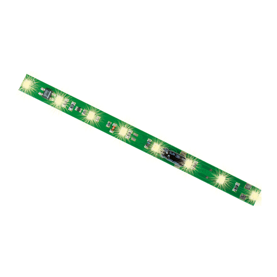
The printed circuit board (PCB) can be adapted
to the size of the car by sawing it through at the
spot shown in fig. 1. The small 32 mm strip is not
intended for further use. Be careful not to damage
the silver connection pads, the components and the
conductor paths on the PCB when sawing.
-
Solder connecting wires to the connection points
shown in fig. 1. All left and right connection pads
are interconnected. Therefore, it is sufficient to
connect only one wire to each side. One side has
to be connected to the left wheel pick-up (resp.
the car ground for Märklin), the other side has to
be connected to the right wheel pick-up of the car
(resp. the current pick-up wiper for Märklin). See fig. 2.
Observe the soldering instructions. (paragraph 4.)
-
Mount the PCB unterneath the roof of the car with
double-sided adhesive tape. The tape must not be
attached to the part marked in fig. 1, as this may get
hot in operation.
3. Soldering Instructions
If you are not practiced at soldering, please first read
these soldering instructions before picking up the
soldering iron. Soldering is something that has to be
learned.
1. Never use soldering paste or fluid when soldering
electronic connections. These contain an acid that
destroys cables, components and conductor paths.
2. As soldering material, use only electronics solder
with a rosin core, which also acts as a fluxing agent.
3. Use a small soldering iron with max. 30 watt power
and a thin soldering tip (< 1 mm). The soldering tip
must be free of scaling so that the heat can be con-
ducted away well. This means that the heat from
the soldering iron must be conducted well to the
point to be soldered.
4. The soldering itself should be done quickly because
soldering for too long can destroy components. It
also leads to loosening of the soldering pads and
conductor paths from PCBs.
5. At first strip the insulation from the ends of the
cable, and twist the stripped ends between your
finger tips. Then presolder the wires. To solder, the
well-tinned soldering tip is placed at the soldering
point so that both components which you want to
connect are contacted. At the same time (not too
much) solder has to be added and heated. As
soon as the solder begins to flow, remove it from
the soldering point. Then wait a moment until the
remaining solder has run well, and then remove the
soldering iron from the soldering point.
6. Ensure that the cable just soldered is not moved
for approx. 5 seconds after you have removed the
soldering iron. Then only a shiny silver, perfect sol-
dering point remains.
7. A clean, unoxidized soldering tip is required for a
perfect soldering point. It is absolutely impossible
to solder cleanly using a dirty soldering tip. You
should therefore always remove excess solder and
dirt from the iron with a moist sponge or a silicon
wiper after making a soldering point.
8. Uninsulated ends of the wire which stand out are
cut off directly above the soldering point with a wire
cutter. We recommend a full-flush wire cutter (like
the hobby-cutter, item 7815 from Viessmann).
9. When welding electronic components, be sure not
to solder for more than 5 seconds, because other-
wise the components will be destroyed.
4. Technical data
Supply voltage:
6 – 24 V DC=/Digital signal
Constant brightness:
from 6 V DC= / AC~
Current consumption:
Dimensions:
ca. W 9 x L 132 mm
Entsorgen Sie dieses Produkt nicht über den (unsortierten)
Hausmüll, sondern führen Sie es der Wiederverwertung zu.
Do not dispose of this product through (unsorted) domestic
waste, supply it to recycling instead.
Änderungen vorbehalten. Keine Haftung für Druckfehler und Irrtümer.
Die aktuelle Version der Anleitung finden Sie auf der Viessmann Homepage
unter der Artikelnummer.
Subject to change without prior notice. No liability for mistakes and printing
errors.
You will find the latest version of the manual on the Viessmann website using
the item number.
Viessmann
Modelltechnik GmbH
Bahnhofstraße 2a
D - 35116 Hatzfeld-Reddighausen
info@viessmann-modell.com
+49 6452 9340-0
www.viessmann-modell.de
H0, TT , N Waggon-Innenbeleuchtung
H0, TT, N Coach lighting
5090 mit 8 weißen LEDs / with 8 white LEDs
5091 mit 8 gelben LEDs / with 8 yellow LEDs
5092 mit 8 warmweißen LEDs /
with 8 warm-white LEDs
Modellbauartikel, kein Spielzeug! Nicht geeignet für Kinder
DE
unter 14 Jahren! Anleitung aufbewahren!
Model building item, not a toy! Not suitable for children
EN
under the age of 14 years! Keep these instructions!
Ce n'est pas un jouet. Ne convient pas aux enfants de
FR
moins de 14 ans ! C'est un produit décor! Conservez cette
notice d'instructions!
Não é um brinquedo! Não aconselhável para menores de
PT
14 anos. Conservar o manual de instruções.
Modelbouwartikel, geen speelgoed! Niet geschikt voor kin-
NL
deren onder 14 jaar! Gebruiksaanwijzing bewaren!
Articolo di modellismo, non è un giocattolo! Non adatto
IT
a bambini al di sotto dei 14 anni! Conservare istruzioni per
l'uso!
Artículo para modelismo. No es un juguete! No recomen-
ES
dado para menores de 14 años! Conserva las instrucciones
de servicio!
Bedienungsanleitung
Operation Manual
1. Wichtige Hinweise
Bitte lesen Sie vor der ersten Anwendung des Produk-
tes bzw. dessen Einbau diese Bedienungsanleitung
aufmerksam durch und bewahren Sie diese auf. Sie
ist Teil des Produktes.
1.1 Sicherheitshinweise
Vorsicht:
Stromschlaggefahr!
6 – 16V AC~
Alle Anschluss- und Montagearbeiten nur bei abge-
schalteter Betriebsspannung durchführen!
Ausschließlich nach VDE/EN gefertigte Modellbahn-
transformatoren verwenden!
30 mA maximal
Stromquellen unbedingt so absichern, dass es bei
einem Kurzschluss nicht zum Kabelbrand kommen
kann.
1.2 Das Produkt richtig verwenden
Dieses Produkt ist bestimmt:
-
Zum Einbau in Modelleisenbahn-Waggons unter
Beachtung der für dieses Produkt geltenden
Verarbeitungshinweise.
-
Zum Betrieb mit einer Betriebsspannung von
maximal 16 V AC~ oder 24 V DC=/Digitalsignal.
-
Zum Betrieb in trockenen Räumen.
Jeder darüber hinausgehende Gebrauch gilt als nicht
bestimmungsgemäß. Für daraus resultierende Schä-
den haftet der Hersteller nicht.
2. Hinweise zum Einbau
-
Die Leiterplatte kann an der in Abb. 1 markierten
Stelle abgesägt und so an die Waggonlänge ange-
passt werden.
-
Das kurze Stück kann nicht weiter verwendet wer-
den. Achten Sie beim Sägen darauf, die silbernen
Anschlusspunkte sowie Bauteile und Leiterbahnen
Made in Europe
der Leiterplatte nicht zu beschädigen.
92489
Made in Europe
Stand 04/sw
09/2020
Ho/Kf
DE

Verwandte Anleitungen für Viessmann 5090


Inhaltszusammenfassung für Viessmann 5090
- Seite 1 (< 1 mm). The soldering tip You will find the latest version of the manual on the Viessmann website using Das kurze Stück kann nicht weiter verwendet wer- the item number. must be free of scaling so that the heat can be con- den.
- Seite 2 Connection for an ad- circuit board Seitenschneider ab-geschnitten, vorzugsweise mit einem Seitenschneider ohne Wate (Schräge) - z. B. ditional buffer capa- dem Bastel-Schneider, Viessmann Art. 7815. citor to bridge longer Fig. 2 Abb. 2 9. Beim Löten an elektronischen Bauteilen ist beson- currentless sections.