Dimplex BT 301 UN Bedienungsanleitung
Fußbodentemperaturregler im flächenschalterrahmen
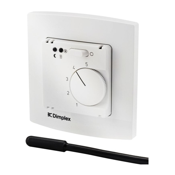
BT
301 UN
Floor temperature controller for installation in a flush mounted switch frame
Thermorégulateur pour le régulation de températures dans des sols, conçu pour
l'installation encastrée avec des cadres de recouvrement plats
Sicherheitshinweis!
Dieses Gerät darf nur durch eine Elektrofachkraft geöffnet und gemäß dem entsprechenden Schaltbild im
Gehäusedeckel / auf dem Gehäuse / in der Bedienungsanleitung installiert werden. Dabei sind die beste-
henden Sicherheitsvorschriften zubeachten.
Die Bedienungsanleitung muss für Bedien- und Wartungspersonal an frei zugänglicher Stelle aufbewahrt
werden.
1. Anwendung
Dieser Regler wurde speziell zur Regelung elektrischer Fußbodenheizungen und Bodentemperiersysteme
entwickelt. Er wird in die Unterputzdose montiert und ist mittels Zwischenrahmen nach DIN 49075, in
nahezu alle Flächenschaltersysteme integrierbar. Für andere, vom Hersteller nicht vorherzusehende
Einsatzgebiete sind die dort gültigen Sicherheitsnormen zu beachten. Eignung hierfür siehe letzten Absatz
– Gewährleistung.
2. Funktion
Der Regler misst mit einem in den Fußboden eingebrachten Fühler die Temperatur und regelt diese mit
einer Schaltdifferenz von ca. 1K. Aus dieser Regelung ergibt sich eine Oberflächentemperatur, die
hauptsächlich durch den Aufbau des Fußbodens bestimmt wird. Bei elektrischen Heizleitungen ist darauf
zu achten, dass diese auch bei Dauerbetrieb den Oberflächenaufbau nicht überhitzen können.
Achtung! Bei beheizten Oberflächen, ausgeführt als Sitzmöbel oder Stellflächen, ist darauf zu achten,
dass die eingestellte Temperatur nicht zur Gesundheitsgefährdung von Personen oder Entflammung von
Gegenständen führt. Zur Vermeidung einer zu hohen Temperatureinstellung, kann der Einstellbereich me-
chanisch unter dem Einstellknopf eingeschränkt werden (vgl. Punkt 3). Der BT 301 UN verfügt über einen
EIN/AUS-Schalter mit dem die Regelung außer Betrieb genommen werden kann. Die rote Lampe zeigt die
aktive Heizung an. Bei Fühlerbruch, Fühlerkurzschluss oder einer Fühlertemperatur unter -20°C wird die
Heizung ausgeschaltet.
2.1. Temperaturabsenkung
Wird an die Klemme ?
Phase L gelegt, wird die Fußbodentemperatur um max. 5K abgesenkt. So ist
über eine externe Uhr oder einen Raumtemperaturregler mit Uhr und 230 V~ Absenkausgang, eine zeitge-
steuerte Temperaturabsenkung und somit eine Energieeinsparung möglich. Das Empfangene Absenk-
signal wird auch bei ausgeschalteter Regelung durch eine grüne Lampe angezeigt. Die tatsächliche
Absenkung der Fußbodentemperatur hängt vom Fußbodenaufbau (Dämmung) sowie der Raumtempera-
tur ab.
3. Montage
Vor dem elektrischen Anschluss wird der Regler wie folgt geöffnet. Knopf (1) mit Schraubendreher abhe-
beln und abnehmen, Schraube (2) lösen, Gehäusedeckel (3) abziehen, Zwischenrahmen (4) und Rahmen
(5) abnehmen.
Nach dem elektrischen Anschluss (vgl. Punkt 6) und Montage des Reglers mittels Tragring in die Unter-
putzdose, wird der Regler in umgekehrter Reihenfolge zum Öffnen wieder geschlossen.
Der Einstellbereich des Reglers kann wie folgt eingeschränkt werden. Arretierstift (8) abziehen, Anschlag
rot (9) für maximal und Anschlag blau (10) für minimal einstellbare Temperatur wählen und den Arretierstift
wieder einstecken.
4. Temperaturfühler
Der Fühler ist im Lieferumfang enthalten. Bei Ersatz Fühlertyp: HF-8/4-K2. Der Fühler kann im Fehlerfall
Netzspannungspotential führen und darf nur mit doppelt isolierter Leitung nach DIN 60730 -1 verlängert
werden. Um gegebenenfalls einen defekten Fühler auszutauschen, wird die Fühlerleitung in einem
Schutzrohr in Wand und Fußboden verlegt. Das geschlossene Schutzrohrende wird mittig zwischen zwei
Heizleitern platziert und der Fühler bis zum Anschlag eingeschoben.
Fühlerwerttabelle NTC
Fühlertemperatur [°C]
10
20
25
30
40
50
5. Technische Daten
Versorgungs- und Schaltspannung:
230V, 50Hz
Schaltvermögen, Kontakt:
16(4)A, Schließer, 230 V~ potentialbehaftet
Regelbereich:
10 ... 50°C
Schaltdifferenz:
ca.1K
Skala:
Merkziffernskala 1 ... 5
Leistungsaufnahme:
ca.1W (ca. 8VA)
Fühlertoleranz:
±1K
Anschlussquerschnitt:
0,5 ... 2,5 mm
Schutzklasse:
II, nach entsprechender Montage
Schutzart:
IP30, nach entsprechender Montage
Betriebstemperatur:
0 ... 40°C
Lagertemperatur:
-20 ... +70°C
Gehäuse-Material/Farbe:
Polycarbonat (PC), Reinweiß (ähnlich RAL 9010)
Ausstattung:
Lampe rot für „Heizen", Lampe grün für „Absenkbetrieb",
Schalter „EIN/AUS", mechanische Bereichseinengung
Stand
12.2006
Fußbodentemperaturregler im Flächenschalterrahmen
2kΩ / 25°C
Fühlerwiderstand [kΩ]
3,66
2,43
2,00
1,65
1,15
0,82
2
Safety information!
D
No persons other than expert electricians only must open this device in due compliance with the related
wiring diagram shown in the housing cover / on the housing / represented in the corresponding operating
instructions. All expert electricians committed to the execution of any such works must comply with the
relevant safety regulations currently operative and in force.
These operating instructions must be kept at a place that can be accessed freely by the operating and/or
servicing personnel in charge.
1. Application
This controller has been specially devised for the control of electric floor heating- and floor temperature
equalization systems. The device is installed in an UP box and can be integrated into almost all currently
available flush switch installation frame systems when using DIN 49075 compliant intermediate frames.
Regarding other applications not to be foreseen by the manufacturer of this device, the safety standards
concerning these applications need to be followed and adhered to. Regarding the aptitude or suitability of
the device for any such application also please pay regard to the warranty information on page two of
these operating instructions.
2. Functioning
The controller measures, based on the data delivered to it by a sensor installed in the floor, the existing floor
temperature and controls it with a switching difference of approx. 1K. The control operations thus performed
result in a surface temperature which is mainly determined by the structure and composition of the related
floor. With electric heating lines care must be taken to ensure that they cannot superheat the surface structure,
even if operated continuously.
Caution! With heated surfaces that have been designed as sitting furniture or that provide special storing
surfaces, care must be taken to ensure that the adjusted temperature does not lead to health risks or to the
inflammation of objects. The setting range of the device can, in order to prevent from the setting of tempera-
tures that are too high, be restricted mechanically by means of a special facility that exists underneath of the
adjusting knob (see section 3). The BT 301 UN is equipped with an ON/OF switch that enables to activate or
deactivate its control operations. The active state of the heating system is indicated by the red lamp that has
been provided for this purpose. The heating system is deactivated in the event of a sensor breakdown or
sensor short-circuit and also in the event the sensor measures a temperature below -20°C.
2.1 Temperature decrease mode
Once the phase L is connected to the terminal
This enables, in combination with an external clock or a clock-controlled room temperature controller with a
230 V~ temperature decrease mode output, to realise a time-controlled decrease of the temperature and,
consequently, to save energy. A green indicator lamp signals the reception of a temperature decrease mode
triggering signal, even with the control system in deactivated condition. The actual decrease of the floor tem-
perature depends on both the composition and structure of the floor (insulation) and on the prevailing room
temperature.
3. Installation
Prior to its electrical connection, the controller must be opened as explained hereafter: Use a screw driver
to lever the knob (1) off and remove the knob. Then loosen the screw (2) and remove the housing cover
(3) by pulling it off. Following this, remove both the intermediate frame (4) and the main frame (5).
Once the electrical connection was finished (see section 6) and the device installed in the UP box using
the support collar, proceed in inverse order as explained hereinbefore with regard to the opening of the
device to reclose it.
The setting range of the controller can be delimited or restricted as follows: Remove the retention pin (8)
first, then bring the red (9) (maximum adjustable temperature) and the blue end stop (10) (minimum adjus-
table temperature) into the desired position and reinsert the lock pin.
4. Temperature sensor
The required sensor is included in the scope of the delivery. As for replacement, a sensor type HF-8/4-K2
must be used. The sensor can, in the event of a breakdown or fault, carry line voltage potential and must
therefore, as specified in DIN 60730-1, be extended only by means of a double-insulated line. To enable
the safe replacement of a defective sensor in case of need, the sensor line is inserted into a protective
tube, which must be laid underneath of the wall or floor surface. For this purpose, the closed end of the
protective tube must be placed centrically between two heating lines and the sensor be inserted until to
end stop.
Table of sensor characteristics: NTC 2kΩ / 25°C
Sensor temperature [°C]
10
20
25
30
40
50
5. Technical data
Supply- and switching voltage:
Switching capacity, contact:
Control range:
Switching difference:
Scale:
Power consumption:
Sensor tolerance:
Connection cross section:
Protection class:
Degree of protection:
Operating temperature:
Storage temperature:
Housing material and colour:
Equipment:
, the floor temperature is decreased by no more than 5K.
Sensor resistance [kΩ]
3.66
2.43
2.00
1.65
1.15
0.82
230V, 50Hz
16(4)A, make contact, 230V~ non-isolated
10 ... 50°C
approx. 1K
note numeral type scale (1 ... 5)
approx. 1W (approx. 8 VA)
±1K
0.5 ... 2.5 mm
2
II (after corresponding installation)
IP30 (after corresponding installation)
0 ... 40°C
-20 ... +70°C
polycarbonate (PC), pure white (similar to RAL 9010)
red lamp for heating mode indication; green lamp for temperature
decrease mode indication, ON/OFF switch; mechanical range
suppression
GB
5 21164 02

Verwandte Anleitungen für Dimplex BT 301 UN


Inhaltszusammenfassung für Dimplex BT 301 UN
- Seite 1 Heizung an. Bei Fühlerbruch, Fühlerkurzschluss oder einer Fühlertemperatur unter -20°C wird die adjusting knob (see section 3). The BT 301 UN is equipped with an ON/OF switch that enables to activate or Heizung ausgeschaltet.
- Seite 2 élevées, être resserrée mécaniquement par moyen d’un mécanisme spécial qui existe en dessous du bouton de réglage (voir chapitre 3). Le BT 301 UN est muni d’un interrupteur MARCHE / ARRET pour l’activation ou désactivation des opérations de réglage. La lampe-témoin rouge prévue à cet effet sert 5.