Dimplex BT 401 UN Bedienungsanleitung
BT 401 UN
Thermorégulateur pour la régulation de températures dans des sols /
Sicherheitshinweis!
Dieses Gerät darf nur durch eine Elektrofachkraft geöffnet und gemäß dem entsprechenden
Schaltbild im Gehäusedeckel / auf dem Gehäuse / in der Bedienungsanleitung installiert
werden. Dabei sind die bestehenden Sicherheitsvorschriften zu beachten. Achtung! Der
Betrieb in der Nähe von Geräten, welche nicht den EMV-Richtlinien entsprechen, kann zur
Beeinflussung der Gerätefunktionen führen. Nach der Installation ist der Betreiber, durch die
ausführende Installationsfirma, in die Funktion und Bedienung der Regelung einzuweisen.
Die Bedienungsanleitung muss für Bedien- und Wartungspersonal an frei zugänglicher
Stelle aufbewahrt werden.
1. Anwendung
Regelung elektrischer Fußbodenheizungen und Bodentemperiersysteme. Montage in der
Unterputzdose (UP-Dose 55 mm). Separat als eigenständiges Gerät oder mittels
Zwischenringen gemäß DIN 49075 in nahezu alle Flächenschaltersysteme integrierbar.
Für andere, vom Hersteller nicht vorherzusehende Einsatzgebiete sind die dort gültigen
Sicherheitsvorschriften zu beachten. Eignung hierfür siehe Punkt 13. Gewährleistung.
2. Funktion
Mit dem Wippenschalter kann die Heizfunktion ein- und ausgeschaltet werden. Die rote
Lampe signalisiert die aktive Heizphase (Heizung Ein). Der Regler misst mit einem im Fuß-
boden eingebrachten Temperaturfühler die Bodentemperatur und schließt bei Unterschrei-
tung der am Einstellknopf eingestellten Soll-Temperatur den Heizkontakt. Die Skala 1 bis 5
entspricht ca. 10 bis 50°C Fußbodentemperatur. Klemme
kung. Wird an diese Klemme die Phase L geschaltet, senkt der Regler den eingestellten
Sollwert um ca. 5°C ab. Die grüne Lampe zeigt den Absenkbetrieb (Energie-Sparmodus)
an.
3. Öffnen des Reglers
Knopf (1) mit Schraubendreher abhebeln – Schraube (2) lösen – Gehäusedeckel (3) abzie-
hen – Schalterrahmen (4) abnehmen.
4. Installation des Reglers
Achtung, vor der Installation Netzspannung allpolig abschalten!
Der elektrische Anschluss erfolgt gemäß dem beigefügten Schaltbild. Die Last darf maximal
16 (2) A bei Nennspannung 230 V~ betragen. Regler (6) mittels Tragring (5) und Schrauben
in der UP-Dose montieren.
5. Installation des Fühlers
Die Fühlerleitung darf nicht parallel zur Lastversorgung (Heizmatte) verlegt werden.
Verlegung innerhalb des Estrichs im Schutzrohr. Schutzrohrende geschlossen. Die Fühler-
installation erfolgt zwischen den Heizschleifen ohne Berührung. Verlängerung der Fühler-
leitung bis 50 m möglich (flexibler Leiter mit Aderendhülsen,Mindestquerschnitt 0,5 mm
Bei Falschanschluss oder im Fehlerfall kann Netzspannung am Fühler anliegen, deshalb ist
der Fühler gemäß EN 60730-2-1 doppelt isoliert. Eine Verlängerung der Fühlerleitung ist
deshalb nur mit doppelter Isolierung gemäß EN 60730-2-1 zulässig.
6. Begrenzung des Einstellbereiches
Stift (7) abziehen – Anschlag rot (8) für Maximaltemperatur und Anschlag blau (9) für Mini-
maltemperatur wählen – Stift (7) zum Verriegeln der Anschläge einstecken.
7. Anschluss Temperaturabsenkung
Bei Verwendung der Funktion „Temperaturabsenkung" ist auf Phasengleichheit zu achten
(siehe Schaltbild). Vor Arbeiten am Regler ist auch die Phase für die Temperaturabsenkung
abzuschalten!
6
5
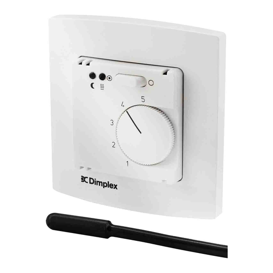
Montage des Reglers
Installation of the controller
02/08/A
Bodentemperaturregler / Floor temperature controller
Regulator temperatury podłogi
dient zur Temperaturabsen-
2
4
3
D
Safety Instructions!
This device should be opened only by an electrical expert and installed in accordance with the
corresponding circuit diagram in the E housing lid / on the housing / in the operating instruc-
tions. Moreover, the existing safety regulations are to be observed. Note! Operating the equip-
ment in the vicinity of equipment, which does not comply with electromagnetic compatibility
guidelines, may affect the functioning of the equipment. After the installation, the operator is to
be oriented by the installing company in the functioning and operation of the control system.
The operating instructions must be kept in a place freely accessible to operating and mainten-
ance personnel.
1. Application
The controller suits especially for the control of temperatures produced by floor heating and
floor temperature equalization systems and is mounted in an UP box (Ø 55 mm). It can
either be mounted as an independent device or be mounted flush using DIN 49075
compliant intermediate frames which allow an adaptation to almost all currently available
flush switch installation frames.
Regarding other applications not to be foreseen by the manufacturer of this device, the
safety standards concerning these applications need to be followed and adhered to.
Regarding the aptitude of the device for any such other application, please refer to section
13. herein (Warranty).
2. Functioning
The rocker switch installed for this purpose serves for the activation and deactivation of the
heating function. The red lamp signals the active state of the heating phase (heating ON).
The controller measures, based on the data delivered to it by a sensor installed in the floor,
the existing floor temperature and closes the heating contact in the event the measured
temperature falls short of the set temperature that has been adjusted at the adjusting knob
beforehand. The scale range from 1 to 5 corresponds to a temperature range from 10 to
50°C. The terminal
serves for the lowering of the actual temperature. When connecting
the phase L to this terminal, the controller lowers the adjusted set value by approx. 5°C. The
green lamp indicates the operation of the device in decrease temperature mode (energy
economizing mode).
3. Opening of the controller
Use a screwdriver in order to lever the knob (1) off. Loosen the screw (2). Remove the
housing cover (3) by pulling it off: Take the switch frame (4) off.
4. Mounting of the controller
Caution: Prior to installing the device, always make sure to cut the mains voltage off
at all poles!
The electrical connection is to be realised in accordance with the enclosed wiring diagram.
At a nominal voltage of 230 V~ the load may not be any higher than max. 16(2)A. Using the
supporting ring (5) and the screws enables to install the controller (6) into the UP box.
5. Installation of the controller
The sensor line must not be laid parallel to the load supply line (heating mat). The sensor line
has to be laid inside a protective tube in the floor pavement (end of the protective tube to be
closed). The installation of the sensor has to be made between the serpentine heating tubes
2
).
in a contactless manner. The sensor line can be extended up to a length of 50 m (flexible wire
with wire-end sleeves, minimum diameter 0.5 mm
occurs, mains voltage can be present at the sensor. This why the sensor used with the device
is a double insulated, EN 60730-2-1 compliant type. Therefore, the wire to be used for an
extension of the sensor line too has to be a double insulated, EN 60730-2-1 compliant type.
6. Limitation of the setting range
Remove the pin (7). Set the red end stop (8) for maximum and the blue one (9) for minimum
temperature. Plug-in the pin (7) to lock the end stops.
7. Temperature decrease connection
When using the temperature decrease function, care must be taken to ensure that the equa-
lity of the phases is observed (see wiring diagram). Prior to performing any works on the
controller, the phase required for the operation in temperature decrease mode too, has to be
cut off!
1
Begrenzung des Einstellbereichs
Limitation of the setting range
1
GB
2
). If not properly connected or if a failure
8
7
9
5 21405 00 (FE)

Verwandte Anleitungen für Dimplex BT 401 UN


Inhaltszusammenfassung für Dimplex BT 401 UN
- Seite 1 BT 401 UN Bodentemperaturregler / Floor temperature controller Thermorégulateur pour la régulation de températures dans des sols / Regulator temperatury podłogi Sicherheitshinweis! Safety Instructions! Dieses Gerät darf nur durch eine Elektrofachkraft geöffnet und gemäß dem entsprechenden This device should be opened only by an electrical expert and installed in accordance with the Schaltbild im Gehäusedeckel / auf dem Gehäuse / in der Bedienungsanleitung installiert...
- Seite 2 8. Technische Daten 8. Technical Data Operating voltage: 230 V/50 Hz Betriebsspannung: 230 V/50 Hz Control range: 10 … 50°C Regelbereich: 10 … 50°C Fühlertoleranz: Sensor tolerance: Switching difference: approx. 1K Schaltdifferenz: ca. 1K Power consumption: approx. 1W Leistungsaufnahme: ca. 1W Temperature decrease: approx.
- Seite 3 Consignes de sécurité ! Uwagi doatyczące bezpieczeństwa! Seuls des électriciens qualifiés sont autorisés à ouvrir cet appareil et à l’installer, conformé- Niniejsze urządzenie może być otwierane wyłącznie przez wykwalifikowanego elektryka. ment au schéma des connexions correspondant qui est collé à l’intérieur du couvercle du Należy instalować...
- Seite 4 DIN. Tylko w tym zakresie, wie ˛ c zapewniamy właściwości produktu. Klient/zleceniodawca ma obowiązek sprawdzenia, czy produkt nadaje sie ˛ do przewidzianego celu zastosowania wzgle ˛dnie możliwość jego zastosowania w warunkach panujących u klienta/zleceniodawcy. W tym zakresie nie udzielamy żadnej gwarancji. Zastrzegamy sobie prawo do wprowadzenia zmian. Glen Dimplex Deutschland GmbH Telefon: +49 (0)9221 709-564 Gerät nicht im allgemeinen Hausmüll entsorgen...