Mettler Toledo IND780 Installationshandbuch
Vorschau ausblenden
Andere Handbücher für IND780:
- Installationsanleitung (581 Seiten) ,
- Kurzanleitung (156 Seiten) ,
- Benutzerhandbuch (148 Seiten)

Verwandte Anleitungen für Mettler Toledo IND780


Inhaltszusammenfassung für Mettler Toledo IND780
- Seite 1 IND780 Terminal Installation Manual Manual de Instalación Installationshandbuch Manuel d’installation Guida all’installazione www.mt.com 64057253 (01/2011) R09...
- Seite 2 IND780 Terminal Installation Manual...
- Seite 3 Restricted Rights. Copyright 2011 METTLER TOLEDO. This documentation contains proprietary information of METTLER TOLEDO. It may not be copied in whole or in part without the express written consent of METTLER TOLEDO. METTLER TOLEDO reserves the right to make refinements or changes to the product or manual without notice.
- Seite 4 64057241. OTE ON IRMWARE EVISIONS This manual describes features and functions of the IND780 terminal with version 6.4.xx firmware. Terminals with version 6.3.xx firmware or lower will differ in some areas. The following lists indicate the key differences between versions: New in version 5.1 –...
- Seite 5 RoHS Compliance Statement. The majority of our products fall within categories 8 and 9. Those categories currently do not fall within the scope of the Directive 2002/95/EG (RoHS) of January 27, 2003. If our products are intended for use in other products which themselves fall within the scope of the RoHS Directive, compliance requirements have to be separately negotiated contractually.
- Seite 6 Met all needs Met most needs Met some needs Did not meet my needs Comments/Questions: DO NOT WRITE IN SPACE BELOW; FOR METTLER TOLEDO USE ONLY Retail Light Industrial Heavy Industrial Custom RESPONSE: Include Root Cause Analysis and Corrective Action Taken.
- Seite 7 FOLD THIS FLAP FIRST NO POSTAGE NECESSARY IF MAILED IN THE UNITED STATES BUSINESS REPLY MAIL FIRST CLASS PERMIT NO. 414 COLUMBUS, OH POSTAGE WILL BE PAID BY ADDRESSEE Mettler-Toledo, Inc. Quality Manager - MTWT P.O. Box 1705 Columbus, OH 43216 Please seal with tape...
- Seite 8 PROPERLY GROUNDED OUTLET ONLY. DO NOT REMOVE THE GROUND PRONG. WARNING! NOT ALL VERSIONS OF THE IND780 ARE DESIGNED FOR USE IN HAZARDOUS (EXPLOSIVE) AREAS. REFER TO THE DATA PLATE OF THE IND780 TO DETERMINE IF A SPECIFIC TERMINAL IS APPROVED FOR USE IN AN AREA CLASSIFIED AS HAZARDOUS BECAUSE OF COMBUSTIBLE OR EXPLOSIVE ATMOSPHERES.
- Seite 9 WARNING! WHEN THIS EQUIPMENT IS INCLUDED AS A COMPONENT PART OF A SYSTEM, THE RESULTING DESIGN MUST BE REVIEWED BY QUALIFIED PERSONNEL WHO ARE FAMILIAR WITH THE CONSTRUCTION AND OPERATION OF ALL COMPONENTS IN THE SYSTEM AND THE POTENTIAL HAZARDS INVOLVED. FAILURE TO OBSERVE THIS PRECAUTION COULD RESULT IN BODILY HARM AND/OR PROPERTY DAMAGE.
- Seite 10 Terminal Essential Services for Dependable Performance of Your IND780 Terminal Congratulations on choosing the quality and precision of METTLER TOLEDO. Proper use of your new equipment according to this Manual and regular calibration and maintenance by our factory-trained service team ensures dependable and accurate operation, protecting your investment. Contact us about a ServiceXXL agreement tailored to your needs and budget.
-
Seite 11: Inhaltsverzeichnis
Contents Chapter 1.0 Introduction ........1-1 IND780 Terminal Versions ............1-1 Warnings and Precautions ............1-3 Operating Environment..............1-3 Temperature and Humidity ..............1-3 Environmental Protection ..............1-3 Hazardous Areas ................1-3 Safe Disposal Requirement ............1-4 Inspection and Contents Checklist ..........1-4 Model Identification ..............1-5 Physical Dimensions .............. - Seite 12 IND780 Installation Manual Harsh Enclosure Cable Glands and Cable Assignments....2-14 Harsh Enclosure Cable Openings............2-14 Installing Cables ................2-15 Main PCB................2-17 Main Board Wiring Connections ............2-17 Switch Settings ................2-22 Master Reset Button ................2-22 LED Interpretation................2-23 Option Boards................2-24 Wiring Connections for Options ............2-24 Analog Load Cell ................2-26...
-
Seite 13: Ind780 Terminal Versions
Introduction DIV 2 AND ZONE 2/22 INSTALLATION IF YOU WISH TO INSTALL THE IND780 IN A DIVISION 2 OR ZONE 2/22 AREA, REFER TO THE DIVISION 2 AND ZONE 2/22 INSTALLATION INSTRUCTIONS INCLUDED ON THE RESOURCE CD PROVIDED WITH THE TERMINAL. FAILURE TO COMPLY WITH THE INSTRUCTIONS PROVIDED THERE COULD RESULT IN BODILY HARM AND/OR PROPERTY DAMAGE. - Seite 14 IND780 Installation Manual • Real-time clock with battery backup • Two serial ports (RS232 and RS232/422/485) for asynchronous, bidirectional communication and print output • 10/100 Base-T Ethernet port • USB Master • 100–240 VAC power input range • Support for the following option boards:...
-
Seite 15: Warnings And Precautions
National Electrical Code (NEC) because of the combustible or explosive atmospheres in those areas. Contact an authorized METTLER TOLEDO representative for information about hazardous applications. When an approved IND780 is installed in an area classified as Division 2 or Zone 2/22, special AC... -
Seite 16: Safe Disposal Requirement
If the container is not damaged, remove the IND780 terminal from its protective package, noting how it was packed, and inspect each component for damage. -
Seite 17: Model Identification
IND780 Instlallation Manual Model Identification The IND780 model number is located on the data plate on the back of the terminal along with the serial number. Refer to Figure 1-1 to verify the IND780 that was ordered. Figure 1-1: IND780 Model Identification Numbers... -
Seite 18: Physical Dimensions
IND780 Installation Manual Physical Dimensions The IND780 terminal physical dimensions for the Panel Mount enclosure are shown in Figure 1-2 in inches and [mm]. Figure 1-2: IND780 Panel Mount Enclosure Dimensions The IND780 terminal physical dimensions for the harsh desk/wall-mount enclosure are shown in Figure 1-3 and Figure 1-4 in inches and [mm]. -
Seite 19: Specifications
IND780 Instlallation Manual Specifications The IND780 terminal conforms to the specifications listed in Table 1-1. Table 1-1: IND780 Specifications IND780 Specifications Enclosure Type Panel Mount stainless steel front panel Harsh environment desk/wall/column-mount type 304 L stainless steel enclosure Dimensions (l × w × d) Panel Mount: 320 mm ×... - Seite 20 IND780 Installation Manual IND780 Specifications Weight Display Displayed resolution of 1,000,000 counts for analog load cell scales Display resolution for high-precision IDNet bases is determined by the specific base used Scale Types Analog load cells or IDNet, High-Precision K Line,...
-
Seite 21: Main Pcb
PDX bases. Analog Load Cell Scale Base The IND780 supports this scale type through an analog load cell interface. The terminal can drive up to sixteen 350-ohm analog load cells, with up to eight 350- ohm load cells on one channel. -
Seite 22: Powercell ® Pdx ® Scale Base
PDX load cell. When used with an external power supply, the IND780 PDX interface can support as many as 24 cells. Up to four independent scale bases can be logically addressed by the terminal. -
Seite 23: Discrete I/O
A-B RIO The A-B RIO option enables data exchange by bi-directional communications using the Discrete Data Transfer or Block Transfer mode. The IND780 Terminal initiates a communication exchange with the PLC approximately 20 times per second utilizing the Allen-Bradley Discrete Data Transfer protocol. This communication is a high-speed, real-time message interface between the IND780 Terminal and the PLC for process control. -
Seite 24: Application Software
Application Software The following application software modules can be added to the IND780 terminal to provide additional functionality for specific workplaces and industries. Axle-780 The Axle-780 application supports vehicle weighing on a single-platform axle scale. -
Seite 25: Taskexpert
® InSite Configuration Tool The IND780 terminal can connect to a PC running InSite (version 2.01 or higher) via Ethernet to provide the following: • Viewing and/or changing configuration • Enabling device-free configuration work before hardware installation •... -
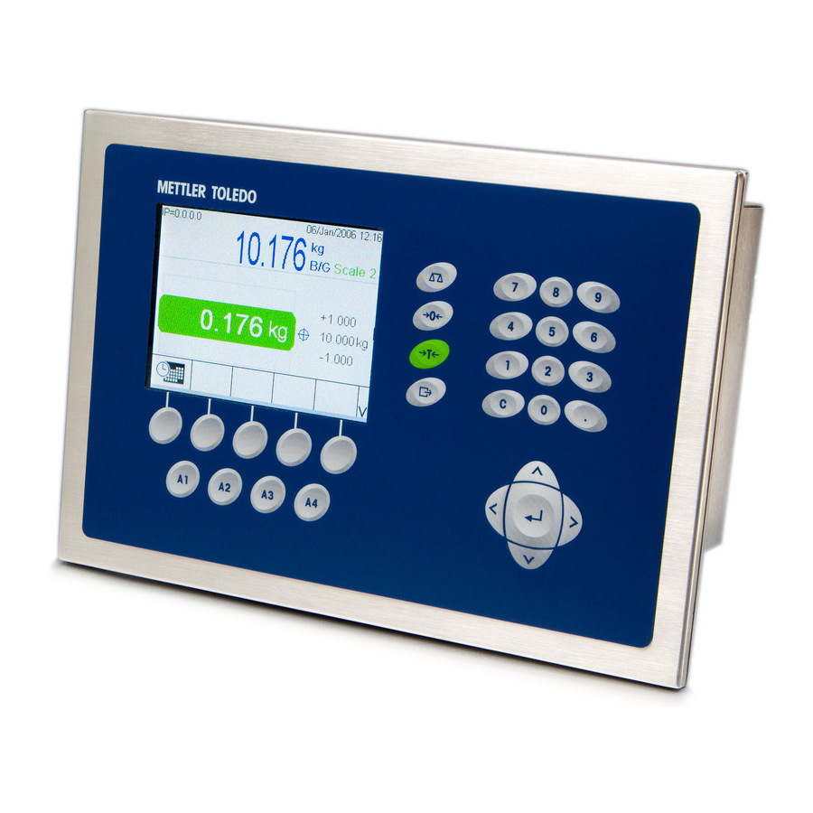
Seite 26: Display And Keyboard
IND780 Installation Manual • Printing documentation of configuration for users’ records • Performing firmware upgrade services for the IND780 In order to support the latest features of the IND780, ensure that the appropriate InSite version is used. Display and Keyboard The IND780 is available with a backlit, active TFT, graphic color LCD. - Seite 27 IND780 Instlallation Manual Figure 1-5 shows the IND780’s display and keyboard layout. Scale function keys Navigation keys Softkeys Application keys Enter key Figure 1-5: The IND780 Front Panel Layout 1-15...
-
Seite 28: Precautions
Installation DIV 2 AND ZONE 2/22 INSTALLATION IF YOU WISH TO INSTALL THE IND780 IN A DIVISION 2 OR ZONE 2/22 AREA, REFER TO THE DIVISION 2 AND ZONE 2/22 INSTALLATION INSTRUCTIONS INCLUDED ON THE RESOURCE CD PROVIDED WITH THE TERMINAL. FAILURE TO COMPLY WITH THE INSTRUCTIONS PROVIDED THERE COULD RESULT IN BODILY HARM AND/OR PROPERTY DAMAGE. -
Seite 29: Opening The Enclosure
On some occasions, the rear cover must be removed to add option cards or to set internal switches. The Panel Mount version of the IND780 is opened by removing the four Phillips head screws on the back panel, circled in... -
Seite 30: Harsh Enclosure
Figure 2-1: Opening the Panel Mount Enclosure Harsh Enclosure The front panel of the harsh enclosure IND780 terminal is locked in place by four spring clips attached to the enclosure body. To gain access to the terminal’s PCB for internal wiring and setting switches, separate the front panel from the enclosure as follows: Place the terminal on a stable, flat surface, with its front panel facing up. -
Seite 31: Mounting The Terminal
IND780 Installation Manual Repeat Step 2 for the other slot, freeing the bottom of the cover from the spring retaining clips. Once the panel is released, lift the bottom of the panel firmly up and out until it clears the edge of the enclosure. -
Seite 32: Harsh Enclosure
IND780 Installation Manual Loosen and remove the eight, 8 mm shoulder nuts holding the backing plate to the enclosure. The gasket should remain in position on the terminal. Figure 2-4 shows two images of the enclosure, one with the backing plate removed to show the gasket, the other with the backing plate installed. -
Seite 33: Desktop Mounting
Desktop Mounting If the IND780 terminal is to be placed on a flat surface, the four rubber feet included with the terminal should be adhered to the bottom of the enclosure to prevent sliding. Peel each foot from the protective paper and press it onto one corner of the bottom of the enclosure, as shown in Figure 2-6. -
Seite 34: Attaching The Enclosure To The Brackets
IND780 Installation Manual Setting Front Panel Orientation Establish whether the terminal will be mounted above or below eye level. If it will be mounted at or below eye level, the orientation of the front panel must be reversed. Follow these steps: 1. - Seite 35 IND780 Installation Manual Figure 2-10 shows the brackets attached to an enclosure. Note the orientation of the enclosure relative to the brackets. Brackets Figure 2-10: Attaching the Wall-Mounting Brackets Marking Mounting Hole Position Mark the position of the mounting holes on the vertical surface per the dimensions shown in Figure 2-11 in inches and [mm], or by holding the terminal up to the surface and marking through the bracket holes.
- Seite 36 IND780 Installation Manual Wall Mounting, Wallboard or Drywall When mounting the IND780 on wallboard, drywall or a similar surface, the anchor should be sized according to the recommended bolt size of 1/4” (6 mm). The recommended mounting hardware is: • Four Toggle Bolts, 1/4” (6 mm), minimum length 2-1/2” to 3” depending on wall thickness, with a pullout force of 900 lb (450 kg) •...
- Seite 37 Figure 2-11). Wall Mounting, Wood Surface When mounting the IND780 to a wooden wall or similar surface, use four #12 screws of at least 1 1/4” (30 mm) length, each with a flat washer of minimum 1/2” (12 mm) diameter.
-
Seite 38: Ferrites And Option Board Cabling
Ferrites and Option Board Cabling Ferrites In order to meet certain electrical noise emission limits and to protect the IND780 from external influences, it is necessary to install a ferrite core on each cable connected to the terminal. Two types of ferrites are supplied with the basic terminal, and additional ferrites may be supplied with each of the options. -
Seite 39: Option Board Cabling
Figure 2-18, before attaching the green connector to the board. Figure 2-18: Option Board Wires Twisted On the IND780 panel mount enclosure, cable shield terminations can be made using the strain relief cable clamp provided on the back cover. Fold the shield braid back evenly over the cable’s insulation sheath and then fasten down the... - Seite 40 Figure 2-19: Shield Wire Termination, Panel Enclosure Analog load cell, POWERCELL MTX and POWERCELL PDX cable shield termination on the IND780 harsh enclosure can be made using the metal cable gland and grommet as shown in Figure 2-24. Other cables’ shield termination can be made on the ground stud inside the enclosure (Figure 2-20).
-
Seite 41: Harsh Enclosure Cable Glands And Cable Assignments
Harsh Enclosure Cable Glands and Cable Assignments On the IND780 panel mount enclosure, cable shield terminations can be made using the strain relief cable clamp provided on the back cover. Fold the shield braid back evenly over the cable’s insulation sheath and then fasten down the cable and shield with the clamp and screw onto the back cover (Figure 2-19). -
Seite 42: Installing Cables
Fourth scale connector or, with insert, COM2 0.16–0.32 [4–8] Installing Cables The IND780 harsh environment terminal is designed to withstand severe washdown environments. However, care must be taken when installing cables and/or connectors that enter the terminal enclosure. To ensure a watertight seal: •... - Seite 43 • A metal cable gland is provided with the Analog Load Cell and POWERCELL MTX and PDX options. To further protect the IND780 from external influences, the cable’s shield wire can be spread out and pressed into cable gland by the grommet, as shown in Figure 2-24.
-
Seite 44: Main Pcb
Ensure that this seal is watertight. Main PCB Main Board Wiring Connections The following connections are made to the IND780 main board: • Ethernet • Optional scale interface boards •... -
Seite 45: Power Connection
A permanently attached line cord supplies AC power to the harsh enclosure version of the IND780 terminal. The panel mount enclosure does not provide an AC power cord – it is designed to have AC wiring connected to the AC power connector, which is plugged into the mating connector on the rear of the chassis. - Seite 46 The terminal requires 100 to 240 VAC (at 400 mA maximum) with a line frequency of 49 to 61 Hz of power. Ethernet and USB Connections The IND780’s Ethernet connection provides a 10/100 base T connection (10/100 Mb) via a standard RJ45 connector. The standard ST30 USB connector allows USB-supported peripherals, such as keyboards, to be attached to the IND780.
- Seite 47 IND780 Installation Manual connections as necessary. Table 2-2 describes the functions for each signal in the COM1 port connector. Figure 2-31: COM1 Port Connector Table 2-2: COM1 Port Connections Signal Function RS-232 Transmit data RS-232 Receive data RS-232 Signal ground...
- Seite 48 IND780 Installation Manual Table 2-3: COM2 Port Connections Signal Function Notes RS-232 Transmit data RS-232 Receive data RS-232 Signal ground TxD+ RS-422/485 Transmit + Jumper to RxD+ for RS-485 TxD- RS-422/485 Transmit - Jumper to RxD- for RS-485 RxD+ RS-422/485 Receive +...
-
Seite 49: Switch Settings
Figure 2-36 indicates the location of this button. This process is described in the IND780 Technical Manual, Chapter 4.0, Service and Maintenance. -
Seite 50: Led Interpretation
IND780 Installation Manual Master reset button Figure 2-36: Main PCB Master Reset Button Location LED Interpretation D30: USB functional ETX Board LED (hidden by lower D73: Ethernet card guide) link D74: Ethernet D13: 5V link active supply D75: 100MB D12: 12V... -
Seite 51: Option Boards
LED is lit steadily, indicating that the core power supply is on. This in turn indicates that both on-board regulators are functioning correctly. Option Boards Wiring Connections for Options Options available for the IND780 terminal include the following: • • Analog Load Cell DeviceNet ®... - Seite 52 IND780 Installation Manual Figure 2-38 shows each of these options, together with its location in the terminal. The connections and board settings for each option are described in the following sections. Figure 2-38: IND780 Options Locations 2-25...
-
Seite 53: Analog Load Cell
Figure 2-39: Analog Load Cell Option Board Jumper Settings One jumper (W1) on the IND780 analog scale option board permits the gain of the analog section to be set to either 2 mV/V or 3 mV/V. The factory default is 3 mV/V, which normally will work well for both 2 mV/V and 3 mV/V load cells. - Seite 54 TSR = Number of Load Cells Ensure that the TSR of the load cell network to be connected to the IND780 has a resistance greater than 43 ohms before connecting the load cells. If the resistance is less than 43 ohms, the IND780 will not operate properly.
- Seite 55 The output is a current-sinking component which can handle from 5 to 30 volt DC signals at a maximum of 35 mA current. A solid-state relay or OPTO 22 is typically connected to buffer the IND780 terminal outputs to a 120 or 220 volt AC signal. LED Interpretation Figure 2-43 indicates the location of LED on the Analog Load Cell board.
-
Seite 56: Powercell Mtx
IND780 Installation Manual Figure 2-43: Analog Load Cell LED Table 2-8: Analog Load Cell LED Color Function Slow blink (~1 Hz) indicates no USB communication with Main PCB Amber Fast blink (~4 Hz) indicates USB communication with Main PCB is... - Seite 57 2 and 3. Connections WARNING! TO AVOID DAMAGE TO THE PCB OR LOAD CELL, REMOVE POWER FROM THE IND780 TERMINAL AND WAIT AT LEAST 30 SECONDS BEFORE CONNECTING OR DISCONNECTING ANY HARNESS. The POWERCELL MTX option board should be placed in slot 1 on the main board, and its ground wire attached to the screw indicated in Figure 2-27 and Figure ®...
- Seite 58 – Black / GND The total maximum cable length from the last junction box to the IND780 terminal depends on the power supply level, number of cells and cable gauge sizes. Refer to Table 2-11 for the recommended maximum cable lengths supported by the IND780 POWERCELL MTX option board using its internal 12VDC supply.
- Seite 59 IND780 Installation Manual Number of 20 Gauge Number of RAAD 20 Gauge CMOS/MTX Cells (meters/feet) Boxes (350Ω cells) (meters/feet) 91/300 If an external 24VDC power supply is used, up to 24 load cells per terminal with the maximum cable length of 900 feet is possible.
-
Seite 60: Powercell Pdx
Jumper Settings The POWERCELL PDX board has several jumpers. The W6 jumper is used to set in the PDX network’s terminating resistor on the IND780. Figure 2-48 shows the jumpers’ locations and settings. Table 2-13 describes the purpose of each setting. - Seite 61 IND780 Installation Manual Connections WARNING! TO AVOID DAMAGE TO THE PCB OR LOAD CELL, REMOVE POWER FROM THE IND780 TERMINAL AND WAIT AT LEAST 30 SECONDS BEFORE CONNECTING OR DISCONNECTING ANY HARNESS. WARNING! THE POWERCELL PDX SCALE INTERFACE BOARD #64064718 (KIT NUMBER 64067252) MUST NOT BE USED IN AN IND780 TERMINAL INSTALLED IN AN AREA CLASSIFIED AS DIVISION 2 OR ZONE 2/22.
- Seite 62 35 mA current. A solid-state relay or OPTO 22 is typically connected to buffer the IND780 terminal outputs to a 120 or 220 volt AC signal. Depending on the number of load cells and the cabling configuration, the IND780 terminal uses either its internal 12 VDC supply (via pins 6 and 7) or an external 24 VDC supply (via pins 7 and 8) to power the load cells.
- Seite 63 2. Trim the inner braid shield and the foil, leaving about 20 mm (0.8 inches) exposed. 3. When installing an IND780 harsh enclosure terminal: 2-36...
- Seite 64 IND780 Installation Manual a. Install the cable gland assembly, metal clamp and the brass sleeve onto the home run cable while sliding back the outer braid shield (Figure 2-51). The inner drain wire should go into the enclosure through the cable gland, while the outer drain wire remains on the outside.
- Seite 65 Figure 2-52: POWERCELL PDX Home Run Outer Braid Termination, Harsh Enclosure 4. To terminate the home run cable’s outer and inner braid shield for an IND780 panel mount terminal, when using a cable gland with the external panel housing, follow the procedure described in step 3, above. Alternatively, when using a conduit hub entry: a.
- Seite 66 Figure 2-54: POWERCELL PDX Home Run Outer Braid Termination, Panel 5. For an IND780 harsh enclosure, to make the power ground connection on pin 7 of the option board terminal strip: a. First, a separate short length of the power ground wire with a ring terminal on one end must be prepared in advance.
- Seite 67 IND780 Installation Manual 6. For an IND780 panel mount enclosure, make the terminations described in step 5 to the external ground stud indicated in Figure 2-56. Inner drain wire and ground wires Panel enclosure grounding stud Ground wire connected to pin...
-
Seite 68: Discrete I/O (Input/Output)
IND780 Installation Manual LED Interpretation Figure 2-57 indicates the locations of LEDs on the POWERCELL PDX board. Table 2-16 describes the function of the LEDs. Figure 2-57: POWERCELL PDX Board LEDs Table 2-16: POWERCELL PDX Board LEDs Function Color Function ON –... - Seite 69 IND780 Installation Manual Figure 2-58: Discrete I/O Board Mode Selector Switch Location Connections The relay output version of the Discrete I/O option provides four isolated inputs and four dry-contact, normally open relay outputs. The inputs can be selected as either active or passive based on the position of the slide switch on the board.
- Seite 70 IND780 Installation Manual Pin 1 Figure 2-60: Discrete I/O Board, Relay Mode Selector Switch Figure 2-61: Discrete I/O Mode Selector Switch, Active Position Active Input Selecting the inputs as active enables connection of switches or other simple devices to trigger an input. No voltage is supplied by the external simple device. An example of how to wire to the active inputs is shown in Figure 2-62.
- Seite 71 Selecting the inputs as passive enables other devices such as PLCs to provide the trigger voltage (typically 24 VDC, 5-30 VDC) to turn the IND780 inputs “on”. An example of wiring to the passive inputs is shown in Figure 2-63. The voltage polarity may be reversed.
-
Seite 72: Idnet
TERMINAL AND WAIT AT LEAST 30 SECONDS BEFORE CONNECTING OR DISCONNECTING ANY HARNESS. For IDNet base load cells, the IND780 terminal supplies 12 VDC for the new T- Brick type, and 30 VDC for the legacy PIK-Brick type. When using an IDNet card in the IND780 terminal, the cable connection from the base is made to a connector on the rear of the housing. -
Seite 73: Serial Option Board
IND780 Installation Manual The IDNet cable is required to connect between the option board and the enclosure case. The cable is configured as shown in Figure 2-67. IDNet Cable 64062067 Color Remarks P1-A P2-8 Green TxD+/RxD+ P1-B P2-9 Blue +30V... - Seite 74 IND780 Installation Manual Pin 1 Figure 2-68: Serial Option Board Figure 2-69: Serial Option Board Connector Port connector assignments for this board are shown in Figure 2-70, and termination for RS232, RS422 and RS485 in Table 2-17. Table 2-17: Serial Option Board Pin Connections...
-
Seite 75: Plc Interface Modules
IND780 Installation Manual Figure 2-70: Connector Terminations for Serial Option Board RS-485 Transmission Line Termination The RS-485 network should include a terminating resistor, installed between the two lines at or on the last node. The terminating resistor should match the characteristic impedance of the transmission line, approximately 120 ohms. -
Seite 76: Profibus Connections (Harsh Enclosure)
(Harsh Enclosure) The PROFIBUS connection to the harsh enclosure is made using a straight nine pin connector inside the IND780 enclosure. Follow the instructions included with the connector to terminate the wires. Figure 2-74 shows the PROFIBUS module for use in the Harsh Enclosure, with its connector at upper right. -
Seite 77: Profibus Connections (Panel Mount Enclosure)
The connector will extend through the cutout in the back panel of the terminal. This connector (or an equivalent) is a standard METTLER TOLEDO part # 64054361. The connector is not supplied by METTLER TOLEDO as part of the option. -
Seite 78: Controlnet Interface
Figure 2-78: ControlNet PLC Module Connections and Components Do not plug an Ethernet cable into the RJ-45 connector shown at left in Figure 2-78. Damage to the IND780 may result. Figure 2-79 shows the array of status indicator LEDs on the ControlNet card (see also Figure 2-78). -
Seite 79: Ethernet / Ip And Modbus Tcp Interface
Figure 2-80 shows an example of a ControlNet cable, and a close-up view of the connector. Note that the connector may be straight or right-angled, as seen here. This cable is not supplied by METTLER TOLEDO. Figure 2-80: ControlNet Cable and Connector... -
Seite 80: Rockwell (Allen Bradley) Rio Connections
IND780 Installation Manual Rockwell (Allen Bradley) RIO Connections Connections to the Remote IO option are made using a three-pin terminal connector on the RIO option. The connection should be wired as shown in Figure 2-83. Figure 2-83: RIO Connection Wiring The part number for the Remote IO cable is Belden 9463. -
Seite 81: Analog Output Connections
(300 meters). The recommended cable for use with the analog output is shielded two-conductor stranded 20-gauge cable (Belden #8762 or equivalent), which is available from METTLER TOLEDO using part number 510220190. Refer to Figure 2-86 for connection and termination information. -
Seite 82: Sealing The Enclosure
Fast blink: board communicating and functioning Sealing the Enclosure When the IND780 terminal is used in a metrologically “approved” application, it must be protected from tampering by use of seals. An optional sealing kit is available from METTLER TOLEDO that contains all the required hardware (Part number 64056538). -
Seite 83: Panel Enclosure Sealing
IND780 Installation Manual Figure 2-89: Use of the Sealing Kit: Wire Through Screw (left), Wire Through Seal (center), Seal Closed (right) Panel Enclosure Sealing The Panel Mount enclosure must be sealed internally and externally. Follow these steps: 1. Ensure that the appropriate approval region has been selected in setup under Scale >... -
Seite 84: Harsh Enclosure Sealing
2. With the front panel installed on the enclosure and snapped into place, thread the free end of the wire seal through either the left or right hole in the IND780 front panel, and through the hole in the retaining clip. - Seite 85 IND780 Installation Manual Thread the end of the wire cable through the hole in the plastic seal and snap the seal shut. Note that, to show the relationship between the components, Figure 2-94 shows the seal not yet shut. Figure 2-94: External Sealing of the Harsh Enclosure...
- Seite 86 IND780 Terminal Manual de instalación...
- Seite 87 METTLER TOLEDO. Esta información no puede copiarse total o parcialmente sin el consentimiento expreso por escrito de METTLER TOLEDO. METTLER TOLEDO se reserva el derecho de refinar o cambiar el producto o el manual sin previo aviso. DERECHOS DE AUTOR METTLER TOLEDO®...
- Seite 88 OTA ACERCA DE LAS EVISIONES DE ICROINSTRUCCIONES DEL ABRICANTE Este manual describe características y funciones de la terminal IND780 con la versión 6.4.xx de instrucciones del fabricante . Las terminales con la versión de instrucciones del fabricante 6.3.xx o anteriores diferirán en algunas áreas. La siguiente lista indica las diferencias esenciales entre las versiones: Nuevo en la versión 5.1: Salida extendida continua;...
- Seite 89 Declaración de conformidad con RoHS La mayoría de nuestros productos entran en las categorías 8 y 9. Estas categorías actualmente no están dentro del ámbito de aplicación de la Directiva 2002/95/EG (RoHS) del 27 de enero de 2003. Si nuestros productos van a usarse en otros productos que a su vez están dentro del ámbito de aplicación de la Directiva RoHS, los requisitos de conformidad deben negociarse en forma separada.
- Seite 90 Cumplió con todos mis requisitos Cumplió con la mayoría de mis requisitos Cumplió con algunos de mis requisitos No cumplió con mis requisitos Comentarios/Preguntas: NO ESCRIBA NADA ABAJO - PARA USO EXCLUSIVO DE METTLER TOLEDO Al detalle Industria ligera Industria pesada Personalizado...
- Seite 91 DOBLE ESTA PARTE PRIMERO NO POSTAGE NECESSARY IF MAILED IN THE UNITED STATES BUSINESS REPLY MAIL FIRST CLASS PERMIT NO. 414 COLUMBUS, OH POSTAGE WILL BE PAID BY ADDRESSEE Mettler-Toledo, Inc. Quality Manager - MTWT P.O. Box 1705 Columbus, OH 43216 Estados Unidos de América Sírvase sellarlo con cinta adhesiva.
- Seite 92 SÓLO EN UNA TOMA CON CONEXIÓN A TIERRA APROPIADA. NO RETIRE EL POLO DE CONEXIÓN A TIERRA ¡ADVERTENCIA! NO TODAS LAS VERSIONES DE LA IND780 ESTÁN DISEÑADAS PARA USARSE EN ÁREAS PELIGROSAS (EXPLOSIVAS). CONSULTE LA PLACA DE IDENTIFICACIÓN DE LA IND780 PARA DETERMINAR SI UNA TERMINAL ESPECÍFICA ESTÁ...
- Seite 93 ¡ADVERTENCIA! CUANDO ESTE EQUIPO ES INCLUIDO COMO PARTE DE UN SISTEMA, EL DISEÑO RESULTANTE DEBE SER REVISADO POR PERSONAL CALIFICADO QUE ESTÉ FAMILIARIZADO CON LA CONSTRUCCIÓN Y OPERACIÓN DE TODOS LOS COMPONENTES EN EL SISTEMA Y LOS PELIGROS POTENCIALES INVOLUCRADOS. EL NO TENER EN CUENTA ESTA PRECAUCIÓN PODRÍA RESULTAR EN LESIONES PERSONALES Y/O DAÑOS A LA PROPIEDAD.
- Seite 94 IND780 Servicios esenciales para el desempeño confiable Enhorabuena por elegir la calidad y precisión de METTLER TOLEDO. El uso adecuado de su nuevo equipo siguiendo este manual, y la calibración y mantenimiento regulares por parte del equipo de servicio formado en fábrica garantizan un funcionamiento fiable y preciso, protegiendo su inversión.
- Seite 95 Contenido Chapter 1.0 Introducción ........1-1 Versiones de la terminal IND780..........1-1 Advertencias y precauciones............1-3 Ambiente operativo..............1-3 Requerimiento de desecho seguro ..........1-4 Inspección y lista de verificación de controles ........ 1-4 Identificación del modelo ............1-6 Especificaciones ................ 1-8 PCB principal................
- Seite 96 IND780 Terminal Manual de instalación Tarjeta principal ............... 2-17 Conexiones para cables ..............2-17 Conexión de energía ...............2-19 Conexiones USB y Ethernet ..............2-20 Conexiones de puertos seriales COM1 y COM2 ........2-21 Interruptores ...................2-23 Botón principal de reinicialización ............2-24 Interpretación de LED ..............2-25 Tarjetas opcionales ..............
-
Seite 97: Versiones De La Terminal Ind780
Introducción INSTALACIÓN DIV 2 Y ZONA 2/22 SI DESEA INSTALAR LA IND780 EN UN ÁREA CLASIFICADA COMO DIVISIÓN 2 O ZONA 2/22, CONSULTE LAS INSTRUCCIONES DE INSTALACIÓN PARA DIVISIÓN 2 Y ZONA 2/22 INCLUIDAS EN EL CD PROPORCIONADO CON LA TERMINAL. LA FALTA DE CUMPLIMIENTO DE ESTAS INSTRUCCIONES PODRÍA RESULTAR EN LESIONES PERSONALES Y/O DAÑOS A LA... - Seite 98 IND780 Terminal Manual de instalación • Pantalla LCD a color, TFT activo de 320 x 240 píxeles y luz de fondo, con capacidad de mostrar el peso con caracteres de hasta 34 mm de alto; presentación de canales múltiples alternos •...
-
Seite 99: Advertencias Y Precauciones
Si no es así, no conecte la terminal bajo ninguna circunstancia. La IND780 tiene una construcción resistente, pero es un instrumento de precisión. Tenga cuidado con la terminal al manejarla e instalarla. -
Seite 100: Áreas Peligrosas
NO LA USE EN ÁREAS CLASIFICADAS COMO PELIGROSAS DEBIDO A LAS ATMÓSFERAS COMBUSTIBLES O EXPLOSIVAS. No todas las versiones de la IND780 pueden operarse en áreas clasificadas como peligrosas según el National Electrical Code (NEC) debido a las atmósferas combustibles o explosivas en esas áreas. Comuníquese con un representante autorizado METTLER TOLEDO para pedir información acerca de las aplicaciones... - Seite 101 IND780 Terminal Manual de instalación Si es necesario enviar la terminal, es mejor usar el contenedor original. Se debe empacar correctamente la terminal IND780 para asegurar su transporte correcto. El paquete debe incluir: Terminal IND780 Bolsa de partes que incluyen •...
-
Seite 102: Identificación Del Modelo
IND780 Terminal Manual de instalación Identificación del modelo El número de modelo de la IND780 se encuentra en la placa de identificación en la parte posterior de la terminal junto con el número de serie. Consulte la Figura 1-1 para verificar la IND780 que pidió. - Seite 103 IND780 Terminal Manual de instalación Dimensiones física físicas de la terminal IND780 para la caja de montaje en panel se muestran en Figura 1-2 en pulgadas y [mm]. Figura 1-2: Dimensiones de la caja de montaje en panel de la IND780 Las dimensiones físicas de la terminal IND780 para la caja de montaje en...
-
Seite 104: Especificaciones
IND780 Terminal Manual de instalación Especificaciones La terminal IND780 concuerda con las especificaciones mostradas en la Tabla 1-1. Tabla 1-1: Especificaciones de la IND780 Especificaciones de la IND780 Tipo de caja Panel frontal de acero inoxidable para montaje en panel... - Seite 105 IND780 Terminal Manual de instalación Especificaciones de la IND780 Pantalla de pesos Resolución mostrada de 1,000,000 números para básculas de celdas de carga analógicas La resolución de pantalla para bases IDNet de alta precisión está determinada por la base específica usada Tipos de básculas...
-
Seite 106: Pcb Principal
Base de báscula de celdas de carga analógicas La IND780 funciona con este tipo de báscula mediante una interfase de celdas de carga analógicas. La terminal puede manejar hasta dieciséis celdas de carga analógicas de 350 ohmios, hasta con ocho celdas de carga de 350 ohmios en un canal. -
Seite 107: Base De Báscula Idnet
™ Base de báscula IDNet La IND780 funciona con la base nueva tipo T-brick de alta precisión y con los transductores anteriores “PIK-brick” a través de la interfase de la báscula IDNet. Este puerto proporciona los +12 V y comunicación necesarios para hacer operar esta base de nuevo estilo. -
Seite 108: E/S Discontinuas
Las opciones de E/S seriales y discontinuas del canal de medición de la báscula están conectadas con la IND780 a través de seis ranuras internas de opciones. Se pueden ordenar varias combinaciones que coincidan con los requisitos de la aplicación en particular. -
Seite 109: Modbus Tcp
La interfase A-B RIO de la IND780 también funciona en el modo de transferencia en bloque para transmitir grandes cantidades de datos. Se pueden encontrar más detalles de esta interfase en el Manual de Interfase PLC de la IND780, en el CD de documentación. -
Seite 110: Software De Aplicaciones
La drive-780 es una solución de software de aplicaciones que puede integrarse a la terminal IND780 para proporcionar pesaje adicional de vehículos de entrada y salida y control de las luces de tráfico o portones asociados con la báscula para camiones. -
Seite 111: Taskexpert
InSite. Pantalla y teclado La IND780 está disponible ya sea con una pantalla LCD gráfica a color con TFT activo. La información de pesaje puede mostrarse en diferentes formatos, incluyendo presentaciones de canales sencillos o múltiples y con o sin una ventana de tara o velocidad. - Seite 112 Tres grupos de cinco teclas programables pueden configurarse para activar una amplia variedad de funciones integradas de la IND780 que van desde ajustar la hora y fecha hasta ingresar a tablas específicas en la memoria para controlar la operación de la IND780.
-
Seite 113: Precauciones
Instalación INSTALACIÓN DIV 2 Y ZONA 2/22 SI DESEA INSTALAR LA IND780 EN UN ÁREA CLASIFICADA COMO DIVISIÓN 2 O ZONA 2/22, CONSULTE LAS INSTRUCCIONES DE INSTALACIÓN PARA DIVISIÓN 2 Y ZONA 2/22 INCLUIDAS EN EL CD PROPORCIONADO CON LA TERMINAL. LA FALTA DE CUMPLIMIENTO DE ESTAS INSTRUCCIONES PODRÍA RESULTAR EN LESIONES PERSONALES Y/O DAÑOS A LA... -
Seite 114: Apertura De Las Cajas
En algunas ocasiones, la tapa posterior debe removerse para instalar tarjetas opcionales o para configurar interruptores internos. La versión de montaje en panel de la IND780 se abre quitando los cuatro tornillos Phillips del... -
Seite 115: Caja Para Ambientes Adversos
Figura 2-1: Apertura de la caja para montaje en panel Caja para ambientes adversos El panel frontal de la caja para ambientes adversos de la terminal IND780 está colocado en su lugar mediante cuatro sujetadores de resorte fijos en el cuerpo de la caja. -
Seite 116: Montaje De La Terminal
IND780 Terminal Manual de Instalación 3. Repita el paso 2 en la otra ranura para liberar la parte inferior de la tapa de las pinzas de sujeción de resorte. 4. Una vez que se libere el panel, levante la parte inferior de éste firmemente hacia arriba y afuera hasta que salga del borde de la caja. -
Seite 117: Caja Para Ambientes Adversos
IND780 Terminal Manual de instalación Afloje y retire las ocho tuercas de 8 mm que sujetan la placa de soporte de la caja. La empaquetadura debe permanecer en su lugar en la terminal (Figura 2-4). Figura 2-4: Placa de soporte instalada Coloque la terminal en el recorte hecho en la parte frontal y sujétela colocando la... -
Seite 118: Montaje En Escritorio
IND780 Terminal Manual de Instalación Montaje en escritorio Cuando la terminal IND780 se va a colocar en una superficie plana, se deben colocar las cuatro bases de goma incluidas con la terminal en la parte inferior para evitar que se resbale. Encuentre las cuatro bases, quite el papel protector del adhesivo, y presione las bases en las esquinas de la parte inferior de la caja como se muestra en la Figura 2-6. -
Seite 119: Fijación De La Caja En Los Soportes
IND780 Terminal Manual de instalación 2. Afloje y quite las dos tuercas que fijan los dos cables metálicos (Figura 2-7) que funcionan como bisagras para la tapa frontal con la caja posterior. Figura 2-7: Ubicaciones de la fijación de la cinta de conexión a tierra 3. - Seite 120 IND780 Terminal Manual de Instalación La Figura 2-10 muestra los soportes fijos en una caja. Observe la orientación de la caja en relación a los soportes. Soportes para montaje en pared Figura 2-10: Fijación de los soportes para montaje en pared Marcación de la posición de los orificios para...
- Seite 121 Montaje en pared, tablarroca o paneles de yeso (Drywall) Cuando se monta la IND780 en tablarroca, panel de yeso o en superficies similares, el anclaje debe ajustarse en tamaño de acuerdo con el tamaño recomendado del perno de 1/4” (6 mm). Los accesorios metálicos de montaje recomendados son: •...
- Seite 122 (vea Figura 2-9, Figura 2-11). Montaje en pared, superficie de madera Cuando monte la IND780 en una pared de madera o superficie similar, use cuatro tornillos #12 de una longitud mínima de 1 1/4” (30 mm), cada uno con una arandela plana de por lo menos 1/2”...
-
Seite 123: Ferritas Y Cableado De Tarjetas Opcionales
Para cumplir con ciertos límites de emisiones de ruido eléctrico y para proteger la IND780 de interferencia externas, es necesario instalar un núcleo de ferrita en cada cable conectado a la terminal. Se suministran dos tipos de ferritas con la terminal básica, y se pueden suministrar adicionales con cada una de las... -
Seite 124: Cableado De Tarjetas Opcionales
IND780 Terminal Manual de Instalación los cables individuales alrededor del núcleo de ferrita dos veces para reducir los efectos del ruido e interferencia eléctrica. Figura 2-15: Núcleo de ferrita sobre el cable eléctrico de montaje en panel Figura 2-16: Núcleo de ferrita sobre el cable de celda de carga analógica Cuando se usa una ferrita tipo abrazadera, puede formarse un bucle en el cable y la ferrita fijarse sobre el punto donde el cable se empalma sobre sí... - Seite 125 IND780 Terminal Manual de instalación Figura 2-18: Cables de la tarjeta opcional torcidos En la caja de montaje en panel del IND780, las terminaciones del blindaje del cable pueden hacerse con la abrazadera para cable de alivio de tensión incluida, sobre la cubierta posterior.
-
Seite 126: Casquillos Para Cables En Cajas Para Ambientes Adversos Y Asignaciones De Cables
IND780 Terminal Manual de Instalación Casquillos para cables en cajas para ambientes adversos y asignaciones de cables Aberturas para cables en cajas para ambiente adverso La Figura 2-21 y la Tabla 2-1 muestran los usos y los límites de los tamaños de cables de las diferentes aberturas en la parte posterior de la caja para ambientes adversos. -
Seite 127: Instalación De Los Cables
COM2 Instalación de los cables La terminal para ambientes adversos de la IND780 está diseñada para resistir ambientes severos de lavado a presión. No obstante, se debe tener cuidado cuando se instalen cables o conectores que ingresen a la caja de la terminal. Para asegurar un sellado hermético:... - Seite 128 • Se proporciona un casquillo para cable con las opciones de celda de carga analógica y de POWERCELL MTX y PDX. Para proteger aún más a la IND780 de influencias externas, el alambre de blindaje del cable puede extenderse y fijarse en este casquillo como se muestra en la Figura 2-24.
-
Seite 129: Tarjeta Principal
Asegúrese de que este sello sea hermético. Tarjeta principal Conexiones para cables Las siguientes conexiones se hacen en la tarjeta principal de la IND780: • Ethernet • Tarjetas de interfase opcionales para báscula • USB •... - Seite 130 IND780 Terminal Manual de Instalación • COM1 • Tarjetas para entrada / salida discontinua • COM2 • Tarjetas opcionales para comunicaciones seriales La tapa posterior de la caja de montaje en panel (Figura 2-28) necesita retirarse para hacer estas conexiones. La caja para ambientes adversos debe abrirse para hacer las conexiones, como muestra la Figura 2-27.
-
Seite 131: Conexión De Energía
Conexión de energía Un cable de línea permanente fijo alimenta corriente alterna a la caja para ambientes adversos de la terminal IND780. La caja para montaje en panel no viene con un cordón eléctrico; está diseñada para tener su cableado de corriente alterna conectado en la energía de corriente alterna, cuyo conector está... -
Seite 132: Conexiones Usb Y Ethernet
49 a 61 Hz de potencia. Conexiones USB y Ethernet La conexión de Ethernet de la IND780 proporciona una conexión 10/100 base T (10/100 Mb) a través de un conector estándar RJ45. El conector USB estándar ST30 permite conectar periféricos que funcionan con USB tales como teclados, a la IND780. -
Seite 133: Conexiones De Puertos Seriales Com1 Y Com2
IND780 Terminal Manual de instalación Conexiones de puertos seriales COM1 y COM2 El puerto COM1 incluye conexiones para RS-232, mientras que el COM2 las incluye para RS-232, RS-422 y RS-485. El parámetro de interfase (en Configuración en Comunicación > Serial) debe establecerse para que coincida con la conexión de hardware que se use. - Seite 134 IND780 Terminal Manual de Instalación Figura 2-32: Cableado de COM1 para RS232 Puerto COM2 Los detalles para el COM2 se encuentran en la Figura 2-33 y en la Figura 2-34. La Tabla 2-7 describe las funciones para cada señal junto con notas para el conector del puerto COM2.
-
Seite 135: Interruptores
IND780 Terminal Manual de instalación Figura 2-34: Cableado de COM2 para equipo externo Conexión terminal de la línea de transmisión RS- La resistencia de la red RS-485 incluye una resistencia de terminación instalada entre las dos líneas en el último nodo. La resistencia de terminación debe cumplir con la impedancia característica de la línea de transmisión, aproximadamente... -
Seite 136: Botón Principal De Reinicialización
La Figura 2-36 marca la ubicación de este botón. Este proceso se describe en el Manual técnico de la IND780, Capítulo 4.0, Servicio y mantenimiento. -
Seite 137: Interpretación De Led
IND780 Terminal Manual de instalación Interpretación de LED D30: USB LED de tarjeta funcional ETX (oculta D73: Conexión debido a la guía Ethernet de la tarjeta inferior) D74: Ethernet activa D13: Alimentación de 5V D75: Red de D12: Alimentación 100 MB... -
Seite 138: Tarjetas Opcionales
IND780 Terminal Manual de Instalación Tarjetas opcionales Las opciones disponibles para la terminal IND780 incluyen las siguientes: • Celda de carga analógica • DeviceNet ® ® ® • PROFIBUS • POWERCELL (caja para ambientes adversos) ® ® ® • PROFIBUS (caja para montaje en panel) •... - Seite 139 Las secciones siguientes describen las conexiones y configuración de la tarjeta para cada una de estas opciones. Celda de carga E/S Discretas analógica (estado sólido) E/S Discretas (relé) Medidor de flujo Salida analógica ® Profibus (ambientes adversos) Figura 2-38: Ubicación de las opciones de la IND780 2-27...
-
Seite 140: Celdas De Carga Analógicas
Una conexión en puente (W1) en la tarjeta opcional de la báscula analógica de la IND780 permite establecer la ganancia de la sección analógica ya sea en 2 mV/V ó 3 mV/V. El valor por defecto es 3 mV/V, el cual normalmente funcionará bien para las celdas de carga de 2 y 3 mV/V. - Seite 141 Las tarjetas para celdas de carga analógicas pueden colocarse en cualquier ranura de la 1 a la 4, para un total de cuatro básculas. La IND780 puede funcionar hasta con 16 celdas de carga. La terminal IND780 está diseñada para energizar hasta ocho celdas de carga de 350 ohmios (o una resistencia mínima de aproximadamente 43 ohmios) por...
- Seite 142 No es necesario configurarla. Un relé de estado sólido u OPTO 22 está comúnmente conectado para efectuar un registro intermedio de las salidas de la terminal IND780 para una señal de 120 ó 220 voltios de corriente alterna. 2-30...
-
Seite 143: Powercell Mtx
IND780 Terminal Manual de instalación Interpretación del LED La Figura 2-43 indica la ubicación de la LED en las tarjetas de celda de carga analógica. La Tabla 2-8 describe las funciones de las LED. Figura 2-43: Ubicacion de la LED de la tarjeta celdas de carga analógica Tabla 2-8: Función de la LED de la tarjeta celdas de carga analógica... - Seite 144 2 y 3. Conexiónes ¡ADVERTENCIA! PARA EVITAR DAÑOS AL PCB O A LA CELDA DE CARGA, INTERRUMPA LA ENERGÍA DE LA TERMINAL IND780 Y ESPERE POR LO MENOS 30 SEGUNDOS ANTES DE CONECTAR O DESCONECTAR CUALQUIER ARNÉS. 2-32...
- Seite 145 – Negro / Tierra La longitud máxima del cable de la última caja de conexiones al terminal IND780 depende del nivel de la fuente de alimentación, número de celdas y diámetros del extensímetro del cable. Consulte la Tabla 2-11 para ver las longitudes de cables máximas recomendadas compatibles con la placa opcional POWERCELL del...
- Seite 146 IND780 Terminal Manual de Instalación Tabla 2-11: Longitudes de cables máximas recomendadas Calibre 20 Número de celdas Calibre 20 Número de cajas (metros / CMOS/MTX (metros / pies) RAAD pies) 274/900 274/900 213/700 137/450 152/500 91/300 121/400 106/350 91/300 Si se utiliza una fuente de alimentación externa de 24 VCC, son posibles hasta 24 celdas de carga por terminal con una longitud de cable máxima de 275 metros.
-
Seite 147: Powercell Pdx
La tarjeta PDX tiene varias conexiones en puente. La conexión en puente W6 se usa para activar la resistencia de terminación de la red PDX en el IND780. La Figura 2-48 muestra las ubicaciones de las conexiones en puente y las configuraciones. - Seite 148 Conexiónes ¡ADVERTENCIA! PARA EVITAR DAÑOS AL PCB O A LA CELDA DE CARGA, INTERRUMPA LA ENERGÍA DEL TERMINAL IND780 Y ESPERE POR LO MENOS 30 SEGUNDOS ANTES DE CONECTAR O DESCONECTAR CUALQUIER ARNÉS. ¡ADVERTENCIA! LA TARJETA DE INTERFASE DE LA BÁSCULA POWERCELL PDX #64064718 (NÚMERO DE PAQUETE 64067252) NO DEBE USARSE EN...
- Seite 149 IND780 para una señal de 120 ó 220 voltios de corriente alterna. Dependiendo del número de celdas de carga y configuración del cableado, el terminal IND780 usa ya sea su alimentación interna 12 VCD (a través de las 2-37...
- Seite 150 8) para energizar las celdas de carga. Consulte la Tabla 2-15 para ver las longitudes máximas de cable recomendadas y el número de celdas de carga que soporta la tarjeta opcional del IND780. Tabla 2-15: Máximas longitudes de cable recomendadas ®...
- Seite 151 2. Recorte el blindaje trenzado interno y el forro metálico, y deje cerca de 20 mm (0.8 pulgadas) expuestos. 3. Cuando instale un terminal de la caja para ambientes adversos IND780: a. Instale el conjunto del casquillo para cable, abrazadera metálica y mango de latón sobre el cable de conexión mientras desliza hacia atrás el...
- Seite 152 4. Para terminar el blindaje de la trenza interno y externo del cable de conexión para un terminal de montaje en panel IND780, cuando se usa un casquillo para cable con una caja para panel externo, siga el procedimiento descrito en el paso 3 más atrás.
- Seite 153 Coloque el cable de tierra trenzado plano alrededor del cable de conexión y el cable de fuga de energía antes de asegurar finalmente todo en la cubierta posterior del IND780 con la abrazadera grande para cable de alivio de tensión incluida con la unidad (Figura 2-54). El otro extremo del cable trenzado plano se termina en la barra de conexión a tierra.
- Seite 154 IND780 Terminal Manual de Instalación 6. Para una caja para montaje en panel del IND780, haga las terminaciones descritas en el paso 5 en el perno de conexión a tierra externo que se indica en la Figura 2-56. Cable de fuga interno y cables de conexión a...
-
Seite 155: E/S Discontinuas (Entradas/Salidas)
IND780 Terminal Manual de instalación Interpretación de LED La Figura 2-57indica la ubicación de los LED en la tarjeta de POWERCELL PDX. La Tabla 2-16 describe las funciones de las LED. Figura 2-57: Ubicaciones de los LED de la tarjeta POWERCELL PDX... - Seite 156 IND780 Terminal Manual de Instalación Figura 2-58: Interruptor selector de modo de E/S discontinuas Conexiónes La versión de salida de relé de la opción de E/S discontinuas proporciona cuatro entradas aisladas y cuatro salidas de relé de contacto en seco normalmente abiertas.
- Seite 157 IND780 Terminal Manual de instalación Figura 2-60: Tarjeta de E/S discontinuas, relé Interruptor selector de modo Figura 2-61: Interruptor selector de modo de E/S discontinuas, posición activa Entrada activa Al seleccionar las entradas como activas se habilita la conexión de interruptores u otros dispositivos simples para activar una entrada.
-
Seite 158: Salidas De Relé
La selección de las entradas como pasivas habilita otros dispositivos como son los PLC para proporcionar el voltaje de accionamiento (comúnmente 24 VDC, 5- 30 VDC) para “encender” las entradas de la IND780. La Figura 2-63 muestra un ejemplo de cableado hacia las entradas pasivas. La polaridad del voltaje puede invertirse. -
Seite 159: Idnet
Nuevo tipo T-Brick, y 30 VDC para el tipo existente PIK-Brick. Cuando use una tarjeta IDNet en la terminal IND780, la conexión del cable de la base se hace a un conector en la parte posterior de la caja. Las tarjetas IDNet vienen con un cable largo y un conector que se adapta al conector en la terminal IND780. - Seite 160 IND780 Terminal Manual de Instalación El cable IDNet se requiere para conectar entre la tarjeta opcional y la estructura de la caja. El cable está configurado como se muestra en Figura 2-67. CABLE IDNET 64062067 COLOR COMENTARIOS P1-A P2-8 VERDE...
-
Seite 161: Tarjeta Opcional Serial
IND780 Terminal Manual de instalación Tarjeta opcional serial Conexiónes La tarjeta opcional serial proporciona un puerto COM extra. La tarjeta puede colocarse ya sea en las ranuras 2 a 6 en el PCB principal. La tarjeta se muestra en la Figura 2-68, y las asignaciones de las clavijas del conector en la Figura 2-69. - Seite 162 IND780 Terminal Manual de Instalación Perno Señal Función Notas RxD- RS-422/485 Recibe - Puente hacia TXD- para RS-485 +5V de salida, 0.5 A máx. +12V +12V de salida, 0.5 A máx. Tierra Figura 2-70: Terminaciones del conector para la tarjeta de opciones seriales Conexión terminal de la línea de transmisión RS-...
-
Seite 163: Módulos De Interfase Del Plc
IND780 Terminal Manual de instalación Módulos de interfase del PLC Conexiónes DeviceNet La tarjeta opcional DeviceNet (Figura 2-71) está conectada a la red mediante un cable de par trenzado específico para DeviceNet. Figura 2-71: Tarjeta opcional DeviceNet La Figura 2-72 indica la numeración de las patillas del conector de la tarjeta opcional DeviceNet. -
Seite 164: Conexiónes Profibus (Caja Para Ambientes Adversos)
La conexión PROFIBUS hacia la caja para ambientes adversos está hecha con un conector de nueve clavijas en ángulo recto en el interior de la caja de la IND780. Siga las instrucciones que se incluyen con el conector para terminar los cables. La Figura 2-74 muestra el módulo PROFIBUS para cajas para ambientes adversos,... - Seite 165 IND780 Terminal Manual de instalación Conecte el enchufe adaptable de nueve clavijas en el conector. La Figura 2-75 muestra las asignaciones de las clavijas. Consulte las instrucciones de cableado incluidas con el conector para terminar los cables. CONECTOR DE INTERFASE PROFIBUS CLAVIJA SEÑAL...
-
Seite 166: Interfase Controlnet
Figura 2-78: Conexiones y componentes del módulo PLC de ControlNet No enchufe un cable Ethernet en el conector RJ-45 mostrado a la izquierda en la Figura 2-78. Puede ocurrir daño a la IND780. La Figura 2-79 muestra una matriz de LED indicadoras de estado en la tarjeta ControlNet (vea también la Figura 2-78). -
Seite 167: Interfase Ethernet / Ip Y Modbus Tcp
IND780 Terminal Manual de instalación Figura 2-80: Cable y conector de ControlNet Interfase Ethernet / IP y Modbus TCP El módulo Ethernet / IP (Figura 2-81) se conecta con la red a través de un cable de conexión Ethernet estándar. Observe que la dirección del módulo está... -
Seite 168: Conexiónes Rockwell (Allen-Bradley) Rio
IND780 Terminal Manual de Instalación Conexiónes Rockwell (Allen-Bradley) RIO Las conexiones para la opción remota de E/S (RIO) se hacen con un conector de terminal de tres clavijas en la opción RIO. La conexión debe cablearse como se muestra en la Figura 2-83. -
Seite 169: Conexiónes De Salida Analógicas
1000 pies (300 metros). El cable recomendado para la salida analógica es calibre 20 trenzado de dos conductores blindado (Belden 8762 o equivalente), el cual está disponible en METTLER TOLEDO con el número de parte 510220190. Consulte la Figura 2-85 para información de conexión y terminación. - Seite 170 IND780 Terminal Manual de Instalación NOTAS 1. LAS SALIDAS DE ERROR DEBEN MONITOREARSE PARA DETERMINAR CUÁNDO ES VÁLIDA LA SEÑAL DE PESO. LAS SEÑALES DE ERROR SON SALIDAS DE SUMIDERO DE CORRIENTE DE COLECTOR ABIERTO. VOLTAJE: CORRIENTE MÁXIMA DE 5-30 VCD, 200 MA.
-
Seite 171: Sellado De La Caja
IND780 Terminal Manual de instalación Sellado de la caja Cuando la terminal IND780 se usa en una aplicación “aprobada” por metrología, debe estar protegida contra alteraciones mediante el uso de sellos. Existe un paquete de sello opcional con METTLER TOLEDO que contiene todos los accesorios necesarios (Parte número 64056538). - Seite 172 IND780 Terminal Manual de Instalación 2. Instale la tapa de seguridad para impedir el acceso a S-1, el interruptor de seguridad de metrología indicado en la Figura 2-91, y los interruptores del PCB principal. Figura 2-90: Interruptor de seguridad de metrología (izquierdo) y tapa instalada (derecha) 3.
-
Seite 173: Sellado De La Caja Para Ambientes Adversos
780. Se recomienda no usar el orificio redondo pequeño que está en el borde inferior del panel frontal del IND780 ya que esto no puede hacerse cuando la unidad está cerrada. 4. Inserte el extremo del cable de alambre a través del orificio del sello de plástico (como se muestra en la Figura 2-94), elimine cualquier holgura en el... - Seite 174 IND780 Terminal Manual de Instalación Figura 2-94: Sellado externo de la caja para ambientes adversos 2-62...
- Seite 175 IND780 Terminal Installationshandbuch...
- Seite 176 © METTLER TOLEDO 2011 Dieses Handbuch darf ohne die ausdrückliche schriftliche Genehmigung von METTLER TOLEDO weder ganz noch teilweise in irgendeiner Form oder durch irgendwelche Mittel, seien es elektronische oder mechanische Methoden, einschließlich Fotokopieren und Aufzeichnen, für irgendwelche Zwecke reproduziert oder übertragen werden.
- Seite 177 ANMERKUNG ZU FIRMWARE-REVISIONEN Dieses Handbuch enthält eine Beschreibung der Funktionen und Funktionalitäten des IND780 Terminals mit Firmware der Version 6.4.xx. Die Funktionsweise von Terminals, die mit Firmware der Version 6.3.xx und älteren Versionen ausgestattet sind, unterscheidet sich in manchen Bereichen. Die folgende Aufstellung gibt die wichtigsten Unterschiede zwischen beiden Versionen an: Neu in Version 5.1 –...
- Seite 178 RoHS Erklärung zur Vorschrifteneinhaltung Die Mehrheit unserer Produkte gehört den Kategorien 8 und 9 an. Diese Kategorien fallen derzeit nicht in den Geltungsrahmen der Direktive 2002/95/EG (RoHS) vom 27. Januar 2003. Wenn unsere Produkte planungsweise in anderen Produkten zur Anwendung kommen sollen, die in den Geltungsrahmen der RoHS-Direktive fallen, müssen die Pflichten zur Einhaltung dieser Vorschriften separat vertraglich festgelegt werden.
-
Seite 179: Kunden-Feedback
Hat meine Anforderungen erfüllt und übertroffen Hat alle Anforderungen erfüllt Hat die meisten Anforderungen erfüllt Hat einige Anforderungen erfüllt Hat meine Anforderungen nicht erfüllt Kommentare/Fragen: DIESES FELD BITTE FREI HALTEN; NUR ZUR VERWENDUNG DURCH METTLER TOLEDO Einzelhandel Leichtindustrie Schwerindustrie Benutzer- definiert... - Seite 180 DIESE KLAPPE ZUERST FALTEN NO POSTAGE NECESSARY IF MAILED IN THE UNITED STATES BUSINESS REPLY MAIL FIRST CLASS PERMIT NO. 414 COLUMBUS, OH POSTAGE WILL BE PAID BY ADDRESSEE Mettler-Toledo, Inc. Quality Manager - MTWT P.O. Box 1705 Columbus, OH 43216 Bitte mit Klebeband versiegeln.
- Seite 181 EINE ORDNUNGSGEMÄSS GEERDETE STECKDOSE ANSCHLIESSEN. DEN ERDUNGSSTIFT NICHT ENTFERNEN. ACHTUNG! NICHT ALLE VERSIONEN DES IND780 SIND ZUR VERWENDUNG IN EXPLOSIONSGEFÄHRDETEN BEREICHEN GEEIGNET. BEZIEHEN SIE SICH AUF DAS DATENSCHILD DES IND780, UM FESTZUSTELLEN, OB EIN BESTIMMTES TERMINAL FÜR DIE VERWENDUNG IN EINEM ALS BRAND- ODER EXPLOSIONSGEFÄHRDET KLASSIFIZIERTEN BEREICH ZUGELASSEN IST.
- Seite 182 ACHTUNG! WENN DIESES GERÄT ALS KOMPONENTE IN EIN SYSTEM INTEGRIERT WIRD, MUSS DIE DARAUS ENTSTEHENDE KONSTRUKTION VON QUALIFIZIERTEM PERSONAL ÜBERPRÜFT WERDEN, DAS MIT DEM BAU UND BETRIEB ALLER KOMPONENTEN IM SYSTEM UND DEN POTENZIELLEN GEFAHREN VERTRAUT IST. DIE NICHTBEACHTUNG DIESER VORSICHTSMASSNAHMEN KÖNNTE ZU VERLETZUNGEN UND/ODER SACHSCHÄDEN FÜHREN.
- Seite 183 Sie über Verbesserungen, Updates und wichtige Mitteilungen bezüglich Ihres Produkts informieren können. 2. Kontaktaufnahme mit METTLER TOLEDO zwecks Service: Der Wert einer Messung steht im direkten Verhältnis zu ihrer Genauigkeit – eine nicht den Spezifikationen entsprechende Waage kann zu Qualitätsminderungen, geringeren Gewinnen und einem höheren Haftbarkeitsrisiko führen.
- Seite 184 Inhaltsverzeichnis Einleitung .........1-1 Kapitel 1.0 IND780-Terminalversionen............1-1 Warn- und Vorsichtshinweise............1-3 Betriebsumgebung ..............1-3 Anforderungen der sicheren Entsorgung ........1-4 Inspektion und Prüfliste für Inhalt..........1-4 Modell-Identifikation ..............1-6 Abmessungen................1-7 Spezifikationen................1-8 Hauptplatine ................1-10 Wägebrücken ................1-10 Wägebrücke mit Analog-Wägezellen ..........1-10 IDNet™-Wägebrücke ...............1-10...
- Seite 185 IND780 Installationshandbuch Hauptrücksetztaste................2-25 Interpretation der LED-Anzeige ............2-26 Optionen ................. 2-27 Verdrahtungsanschlüsse für Optionen..........2-27 Analog-Wägezellenplatine..............2-29 POWERCELL MTX ................2-32 POWERCELL PDX ................2-36 Diskrete I/O- (Eingang/Ausgang) ............2-44 IDNet.....................2-48 Serielle Optionsplatinenanschlüsse ...........2-50 PLC-Schnittstellenmodule ............2-51 DeviceNet-Anschlüsse ..............2-51 PROFIBUS-Anschlüsse (Gehäuse für raue Umgebungen) .....2-53 PROFIBUS-Anschlüsse (Gehäuse für den Schalttafeleinbau)....2-53 ControlNet-Schnittstelle ..............2-55...
-
Seite 186: Kapitel 1.0 Einleitung
Einleitung INSTALLATION DIV 2 UND ZONE 2/22 SOLL DAS IND780 IN EINEM BEREICH DER DIVISION 2 ODER ZONE 2/22 INSTALLIERT WERDEN, SIEHE DIE ANWEISUNGEN ZUR INSTALLATION IN BEREICHEN DER DIVISION 2 UND ZONE 2/22, DIE AUF DER IM LIEFERUMFANG DES TERMINALS ENTHALTENEN RESSOURCEN- CD ZU FINDEN SIND. - Seite 187 Installationshandbuch zum IND780 • Unterstützung für bis zu (16) 350 Ω-Analog-Wägezellen pro Terminal mit bis zu (8) 350 Ω-Analog-Wägezellen pro Waagenkanal • Aktive TFT-Farb-LCD mit Hintergrundbeleuchtung und Gewichtsanzeige mit Zeichen bis zu einer Höhe von 34 mm, 320 x 240 Pixel; alternative Mehrkanalanzeige •...
-
Seite 188: Warn- Und Vorsichtshinweise
übereinstimmt. Wenn dies nicht der Fall ist, darf das Terminal unter keinen Umständen angeschlossen werden. Das IND780-Terminal ist zwar robust gefertigt, es ist aber auch ein Präzisions- instrument. Beim Umgang mit dem Terminal und dessen Installation muss daher umsichtig vorgegangen werden. -
Seite 189: Explosionsgefährdete Bereiche
National Electrical Code (NEC; US-Elektrovorschrift) aufgrund brennbarer oder explosiver Umgebungen als explosionsgefährdet eingestuft wurden. Wenden Sie sich an Ihren befugten Vertreter von METTLER TOLEDO, wenn Sie Informationen über Anwendungen in explosionsgefährdeten Bereichen benötigen. Wenn ein zugelassenes IND780-Terminal in einem Bereich installiert wird, der als Division 2 oder Zone 2/22 klassifiziert ist, müssen besondere... - Seite 190 Installationshandbuch zum IND780 Wenn das Terminal wieder verschickt werden muss, sollte am besten der Originalversandbehälter verwendet werden. Das IND780-Terminal muss richtig verpackt werden, um einen sicheren Transport zu gewährleisten. Im Lieferumfang sollten folgende Teile enthalten sein: IND780-Terminal Dokumentations-CD (enthält alle •...
-
Seite 191: Modell-Identifikation
Installationshandbuch zum IND780 Modell-Identifikation Die IND780-Modellnummer befindet sich zusammen mit der Seriennummer auf dem Datenschild auf der Rückseite des Terminals. Beziehen Sie sich auf Abbildung 1-1, um sicherzustellen, dass das IND780 bestellt wurde. Abbildung 1-1: IND780-Modellidentifikationsnummern... -
Seite 192: Abmessungen
Schalttafeleinbau sind in Abbildung 1-2 in Zoll und [mm] angegeben. Abbildung 1-2: Abmessungen des IND780-Gehäuses für den Schalttafeleinbau Die Abmessungen des IND780-Terminals des Gehäuses für raue Umgebungen für die Tisch-/Wandmontage sind in AAbbildung 1-3 und Abbildung 1-4 in Zoll und [mm] angegeben. -
Seite 193: Spezifikationen
Installationshandbuch zum IND780 Spezifikationen Das IND780-Terminal entspricht den in Tabelle 1-1 aufgeführten Spezifikationen. Tabelle 1-1: IND780-Spezifikationen IND780-Spezifikationen Gehäusetyp Edelstahlvorderplatte für den Schalttafeleinbau Tisch-/Wand-/Säulenmontage in rauen Umgebungen, Edelstahlgehäuse 304 L Abmessungen (L × B × T) Schalttafeleinbau: 320 mm × 220 mm × 110 mm Raue Umgebung: 299 mm ×... - Seite 194 Installationshandbuch zum IND780 IND780-Spezifikationen Gewichtsanzeige Anzeigeauflösung 1.000.000 Zählungen für Analog- Wägezellen Anzeigeauflösung für Hochpräzisions-IDNet-Wägebrücken richtet sich nach der verwendeten Wägebrücke Waagentypen Analog-Wägezellen oder IDNet, High-Precision K Line (T- Brick-Typ ist Standard), POWERCELL MTX, POWERCELL PDX, SICS Anzahl der Zellen Acht 350-Ohm-Wägezellen (2 oder 3 mV/V) pro Analogkanal;...
-
Seite 195: Hauptplatine
Hostkommunikation, kontinuierliche Ausgabe, ASCII-Befehlseingabe (C, T, P, Z), ASCII-Zeicheneingabe, Berichtsausdruck, Drucken von Gesamtsummen oder Anschluss an ein Remote-ARM100-Modul. Wägebrücken Das IND780 unterstützt Analog-, IDNet-, SICS- POWERCELL MTX- und POWERCELL PDX-Wägebrücken. Wägebrücke mit Analog-Wägezellen Das IND780 unterstützt diesen Waagentyp mit einer Analog-Wägezellenschnitt- stelle. -
Seite 196: Sics-Wägebrücke
Regel bei Fahrzeugwaagen- und Tankwäge- anwendungen zum Einsatz kommt, in denen die PDX-Wägezelle verwendet wird. Bei der Verwendung mit einem externen Netzteil kann die IND780 PDX-Schnittstelle bis zu 24 Zellen unterstützen. Bis zu vier unabhängig Wägebrücken können vom Terminal logisch adressiert werden. -
Seite 197: Diskrete I/O
Ausgänge) sowie weitere 32 Eingänge und 48 Ausgänge über maximal acht Remote-I/O-Module unterstützt. Serielle Ports Zusätzliche Kommunikationskarten bieten eine RS-232-, RS-422- oder RS-485- Kommunikation bei Geschwindigkeiten von 300 bis 115.2k Baud. Im IND780 können maximal zwei serielle Kommunikationskarten installiert werden. 1-12... -
Seite 198: Plc-Schnittstellen
Übertragung größerer Datenmengen. Weitere Einzelheiten zu dieser Schnittstelle finden Sie im IND780 PLC-Schnittstellenhandbuch auf der Dokumentations-CD. PROFIBUS DP Das IND780-Terminal kommuniziert gemäß DIN 19 245 mit einem PROFIBUS DP Master. Die PROFIBUS-Option besteht aus einem Modul und Firmware, die im IND780-Terminal resident ist und den Datenaustausch ausführt. -
Seite 199: Analogausgang
Ausdrucken von Kontrolltickets für Signalisierung von Fahranweisungen überladene LKWs Drive-780 Die drive-780-Software ist eine Anwendungslösung, die in das IND780-Terminal integriert werden kann, um zusätzliche Fahrzeugwägevorgänge für Ankommend/Abfahrend sowie die Steuerung von Ampeln oder Toren bei einer LKW-Waage zu ermöglichen. Enthalten sind wie folgt: •... -
Seite 200: Taskexpert
Ausgangspunkt verwendet werden. ® InSite -Konfigurationstool Das IND780-Terminal kann über Ethernet an einem PC mit InSite (Version 2.01 oder höher) angeschlossen werden, sodass Folgendes möglich ist: • Ansicht und/oder Änderung der Konfiguration • Durchführung von gerätefreien Konfigurationsarbeiten vor der Hardware- Installation •... - Seite 201 Symbole von bis zu fünf Softkeys zur Verfügung. Es können drei Sätze mit fünf Softkeys konfiguriert werden, um eine Vielfalt von integrierten Funktionen des IND780 zu aktivieren, die von der Einstellung von Zeit und Datum über den Zugriff auf spezifische Speichertabellen bis zur Steuerung des Betriebs IND780 reichen.
-
Seite 202: Kapitel 2.0 Installation
Installation INSTALLATION DIV 2 UND ZONE 2/22 SOLL DAS IND780 IN EINEM BEREICH DER DIVISION 2 ODER ZONE 2/22 INSTALLIERT WERDEN, SIEHE DIE ANWEISUNGEN ZUR INSTALLATION IN BEREICHEN DER DIVISION 2 UND ZONE 2/22, DIE AUF DER IM LIEFERUMFANG DES TERMINALS ENTHALTENEN RESSOURCEN- CD ZU FINDEN SIND. -
Seite 203: Öffnen Des Gehäuses
DIESER VORSICHTSMASSNAHMEN KÖNNTE ZU EINER BESCHÄDIGUNG ODER DER ZERSTÖRUNG DES GERÄTES UND/ODER ZU VERLETZUNGEN FÜHREN. Öffnen des Gehäuses Die Verfahren für das Öffnen des IND780-Terminals sind für das Gehäuse für den Schalttafeleinbau und das Gehäuse für raue Umgebungen jeweils anders und werden in den folgenden Abschnitten beschrieben. -
Seite 204: Gehäuse Für Raue Umgebungen
Installationshandbuch zum IND780 entfernt werden, um Optionskarten einzubauen oder interne Schalter einzustellen. Die IND780-Version für den Schalttafeleinbau wird geöffnet, indem die vier Kreuzschlitzschrauben auf der Rückplatte ausgebaut werden (in Abbildung 2-1 eingekreist). Die Rückplatte kann dann entfernt werden. Abbildung 2-1: Öffnen des Gehäuses für den Schalttafeleinbau Gehäuse für raue Umgebungen... -
Seite 205: Montage Des Terminals
Installationshandbuch zum IND780 2. Die Spitze eines Flachkopfschraubendrehers in einen der beiden Schlitze an der Kante der Vorderplattenbaugruppe einführen (siehe Abbildung 2-2). Die Oberseite der Vorderplatte fest nach unten gegen das Gehäuse drücken, um den Druck auf die Halteklammer zu entlasten; den Schraubendreher dann gegen das Gehäuse drücken, bis ein Knacken zu hören ist. - Seite 206 Installationshandbuch zum IND780 Abbildung 2-3: Plattenausschnittabmessungen Die acht 8-mm-Ansatzmuttern, mit denen der Aufspannkörper am Gehäuse befestigt ist, lösen und entfernen. Die Dichtung sollte am Terminal in Position bleiben. Abbildung 2-4 zeigt das Gehäuse mit installiertem Aufspannkörper. In Abbildung 2-5 ist der Aufspannkörper ausgebaut und die Dichtung ist auf der Rückseite der Stirnplatte sichtbar.
-
Seite 207: Gehäuse Für Raue Umgebungen
Installationshandbuch zum IND780 DICHTUNG GEHÄUSE AUFSPANNKÖRPER ANSATZMUTTERN, 5 mm Abbildung 2-5: Schalttafelmontage, Seitenansicht Gehäuse für raue Umgebungen Das Gehäuse für raue Umgebungen besteht aus Edelstahl und wurde so konzipiert, dass es auf einer flachen Oberfläche, z. B. einem Tisch oder Schreibtisch aufge- stellt werden kann. -
Seite 208: Vorbereitung Zur Wandmontage
Installationshandbuch zum IND780 Tischmontage Wenn das IND780-Terminal auf einer flachen Fläche aufgestellt wird, sollten die im Lieferumfang des Terminals enthaltenen vier Gummifüße auf die Unterseite des Gehäuses geklebt werden, um ein Rutschen zu vermeiden. Die vier Gummifüße lokalisieren, das Schutzpapier vom Klebstoff abziehen und die Füße auf die Ecken an der Unterseite des Gehäuses drücken (siehe Abbildung 2-6). -
Seite 209: Einstellung Der Vorderplattenausrichtung
Installationshandbuch zum IND780 Einstellung der Vorderplattenausrichtung Es muss festgelegt werden, ob das Terminal über oder unter Augenhöhe montiert wird. Wenn es auf oder unter Augenhöhe montiert wird, muss die Ausrichtung der Vorderplatte umgekehrt werden. Diese Schritte befolgen: 1. Das Gehäuse wie im Abschnitt „Öffnen der Gehäuse“ beschrieben öffnen. -
Seite 210: Anbringen Des Gehäuses An Den Halterungen
Installationshandbuch zum IND780 Anbringen des Gehäuses an den Halterungen Nach Befestigung der Halterungen an der Wandoberfläche kann das Gehäuse mit den vier M5-Schrauben, die im Lieferumfang des Terminals enthalten sind, montiert werden. Eine Halterung ist in Abbildung 2-9 mit den Schlitzlöchern dargestellt. -
Seite 211: Markieren Der Montagelochposition
Sicherheitsbrille, Ohrenschutz und Handschuhe getragen werden. Wandmontage, Gipskarton- oder Gipsplatte Bei der Montage des IND780 an einer Gipskarton- oder Gipsplatte oder einer ähnlichen Oberfläche sollte die Ankergröße entsprechend der empfohlenen Bolzengröße von 1/4” (6 mm) ausgelegt sein. Empfohlene Befestigungsmittel sind: •... -
Seite 212: Wandmontage, Beton Und Zementblöcke
9. Die Schrauben per Hand so weit drehen, bis sie fest an der Montageplatte sitzen. Abbildung 2-13 zeigt Mutter, Unterlegscheibe und Bolzen installiert. Wandmontage, Beton und Zementblöcke Bei der Montage des IND780 an einer Zementblock-, Beton- oder ähnlichen Wand ist der empfohlene Bolzen: • Beton-Hülsenanker nach UL-Listing, Größe 1/4” (6 mm), Mindestversenkung 1/2”... -
Seite 213: Wandmontage, Holzoberfläche
Montagehalterungen einzugreifen (siehe Abbildung 2-9 und Abbildung 2-11). Wandmontage, Holzoberfläche Bei der Montage eines IND780-Terminals an einer Holzwand oder ähnlichen Oberfläche vier Schrauben Nr. 12 mit einer Mindestlänge von 1 1/4” (30 mm) und jeweils einer Flachscheibe mit einem Mindestdurchmesser von 1/2” (12 mm) verwenden. -
Seite 214: Ferrite Und Optionsplatinenverkabelung
Ferrite Um gewisse Grenzwerte in Bezug auf Rauschimpulse einzuhalten und das IND780-Terminal vor externen Einflüssen zu schützen, muss auf jedem Kabel, das am Terminal angeschlossen ist ein Ferritkern installiert werden. Mit dem Grund- terminal werden zwei Ferritkerne mitgeliefert, und weitere Ferrite können mit jeder der Optionen bereitgestellt werden. -
Seite 215: Optionsplatinenverkabelung
(siehe Abbildung 2-18), bevor der grüne Steckverbinder an der Platine angeschlossen wird. Abbildung 2-18: Zusammengedrehte Optionsplatinendrähte Auf dem Gehäuse des IND780 für den Schalttafeleinbau können Kabelabschirmungsabschlüsse mithilfe der Zugentlastungskabelklemme auf der hinteren Abdeckung vorgenommen werden. Biegen Sie den Abschirmungsdraht gleichmäßig über die Kabelummantelung zurück, befestigen Sie das Kabel und die... - Seite 216 Abbildung 2-19: Abschluss des Abschirmungsdrahts, Gehäuse für den Schalttafeleinbau Abschirmungsabschlüsse für Analog-Wägezellen-, POWERCELL MTX- und POWERCELL PDX-Kabel am IND780-Gehäuse für raue Umgebungen können mithilfe des Kabelstutzens aus Metall und der Gummitülle vorgenommen werden (siehe Abbildung 2-24). Abschirmungsanschlüsse anderer Kabel können am Erdungsstift im Gehäuse vorgenommen werden (Abbildung 2-20).
-
Seite 217: Kabelöffnungen Für Das Gehäuse Für Raue Umgebungen
Installationshandbuch zum IND780 Kabelöffnungen für das Gehäuse für raue Umgebungen Abbildung 2-21 und Tabelle 2-1 zeigt die Verwendung und Kabelgrößengrenzen der verschiedenen Öffnungen auf der Rückseite des Gehäuses für raue Umgebungen. Zur leichteren Bezugnahme ist der Mustercode aufgeführt. Ethernet Waage 1... -
Seite 218: Kabelstutzen Und Kabel Für Das Gehäuse Für Raue Umgebungen
Abbildung 2-23: Kabelführung durch Gummitülle, Mutter und Kabelschuh • Im Lieferumfang der Analog-Wägezelle und der POWERCELL MTX- und PDX- Optionen ist ein Kabelstutzen aus Metall enthalten. Um das IND780 noch besser von externen Einflüssen zu schützen, kann der Abschirmungsdraht des Kabel gespreizt und an diesem Kabelstutzen befestigt werden (siehe Abbildung 2-24). - Seite 219 Installationshandbuch zum IND780 Abbildung 2-24: Installation des Kabelstutzens aus Metall mit angeschlossenem Abschirmungsdraht • Die Gummitülle in den Rumpf des Kabelschuhs drücken (siehe Abbildung 2-25). Gummitülle in Kabelschuh Abbildung 2-25: Gummitülle in Körper des Kabelschuhs • Das Kabel durch die Gummitülle bewegen, um die Länge im Gehäuse anzupassen.
-
Seite 220: Hauptplatine
Installationshandbuch zum IND780 festgezogen wird, damit das Kabel abgedichtet ist. Darauf achten, dass diese Abdichtung wasserdicht ist. Hauptplatine Verdrahtungsanschlüsse Die folgenden Anschlüsse werden an der Hauptplatine des IND780 hergestellt: • Ethernet • Optionale Waagenschnittstellenplatinen • USB • Optionale PLC-Schnittstellenplatine • COM1 •... -
Seite 221: Stromanschluss
Abbildung 2-28: Verdrahtungsanschlüsse, Draufsicht, Gehäuse für raue Umgebungen Stromanschluss Die Netzstromversorgung der IND780-Version für raue Umgebungen erfolgt über ein permanent angeschlossenes Netzkabel. Das Gehäuse für den Schalttafeleinbau wird nicht mit einem Netzkabel geliefert – es ist so konstruiert, dass die Wechsel- stromverdrahtung mit dem Wechselstromanschluss verbunden wird, der in den passenden Steckanschluss auf der Rückseite des Chassis eingesteckt wird. -
Seite 222: Ethernet- Und Usb-Anschlüsse
Gefahrenzustand führen, wenn im Gerät ein Kurzschluss entsteht. Ein guter Erdungsanschluss hilft, externe Rauschimpulse so weit wie möglich auszuschalten. Das IND780-Terminal sollte keine Stromleitungen mit Geräten mitbenutzen, die Störimpulse erzeugen. Zur Sicherstellung einer zuverlässigen Erdung sollte ein im Handel erhältlicher Abzweigschaltkreisanalysator verwendet werden. - Seite 223 Installationshandbuch zum IND780 verwendeten Hardwareanschluss übereinstimmt. Dieser Parameter steuert die Sende- und Empfangsleitungen. COM1 Serielle Port Abbildung 2-31 gibt an, welche Klemme welches Signal auf dem COM1-Port darstellt, und Abbildung 2-32 zeigt, wie der Port für eine RS232-Verbindung verdrahtet wird. Die Anschlüsse nach Bedarf herstellen. Tabelle 2-2 beschreibt die Funktionen für jedes Signal im COM1-Portanschluss.
- Seite 224 Installationshandbuch zum IND780 Abbildung 2-32: COM1-Verdrahtung für RS232 COM2 Serielle Port Details für COM2 sind in Abbildung 2-33 und Tabelle 2-3 enthalten. Abbildung 2-33: COM2-Portverbindungen Tabelle 2-3: COM2-Portverbindungen Steck Signal Funktion Anmerkungen RS-232 Daten senden RS2TX RS2RX RS-232 Daten empfangen...
-
Seite 225: Hauptplatinenschalter
Installationshandbuch zum IND780 Abbildung 2-34 zeigt einige Beispiele von Anschlüssen von externen Geräten. Abbildung 2-34: COM2-Verdrahtung für externe Geräte RS-485 Übertragungsleitungsterminierung Das RS-485 Netzwerk sollte einen Abschlusswiderstand enthalten, der an oder auf dem letzten Knoten zwischen den beiden Leitungen installiert ist. Der Abschluss- widerstand sollte auf die charakteristische Impedanz der Übertragungsleitung, etwa... -
Seite 226: Hauptrücksetztaste
Werkstandardwerte zurückzusetzen wird die Hauptrücksetztaste neben der Batterie gedrückt. In Abbildung 2-36 ist die Position dieser Taste umkreist. Dieses Verfahren wird im IND780 Technischen Handbuch, Kapitel 4.0, Service und Wartung, beschrieben. Um auch Waagendaten zurückzusetzen, muss S2 (in Abbildung 2-36 in der AUS-Position dargestellt) in die AN-Position gebracht werden, bevor die Hauptrücksetzung stattfindet. -
Seite 227: Interpretation Der Led-Anzeige
Installationshandbuch zum IND780 Interpretation der LED-Anzeige D30: USB- funktional ETX-Board-LED (von der unteren D73: Kartenführung Ethernet-Link verdeckt) D74: Ethernet- D13: 5V aktiv Versorgung D75: 100- D12: 12V MB-netzwerk Versorgung D72: Software-Flag Abbildung 2-37: Positionen des Hauptplatines LED Tabelle 2-5: Funktionen des Hauptplatines LED... -
Seite 228: Optionen
Installationshandbuch zum IND780 Optionen Verdrahtungsanschlüsse für Optionen Für das IND780-Terminal sind folgende Optionen erhältlich: Analog-Wägezelle DeviceNet™ • • ® ® ® POWERCELL PROFIBUS (Schalttafeleinbau) • • ® ® POWERCELL • ® PROFIBUS (Gehäuse für raue • Umgebungen) IDNet-Waagenschnittstelle • SICS High Precision-Waagenschnittstelle ControlNET™... - Seite 229 Abbildung 2-38 zeigt, wo sich diese Optionen im Terminal befinden. Die Anschlüsse und Einstellungen für jede dieser Optionen werden in den folgenden Abschnitten beschrieben. Analog- Wägezelle DI/O (Festkörperrelais) Serielle DI/O (Relais) Durchflussmesser Analogausgang ® PROFIBUS (Raue Umgebungen) ® PROFIBUS (Schalttafeleinbau) Abbildung 2-38: Positionen der IND780-Optionen 2-28...
-
Seite 230: Analog-Wägezellenplatine
Verstärkungs-Drahtbrücke Abbildung 2-39: Analog-Wägezellen-Optionsplatine Drahtbrücke Eine Drahtbrücke (W1) auf der IND780-Analogwaagen-Optionsplatine ermöglicht die Einstellung der Verstärkung entweder auf 2 mV/V oder 3 mV/V. Die Werks- einstellung ist 3 mV/V, die für 2 mV/V- und 3 mV/V-Wägezellen sehr gut funktioniert. Wenn 2 mV/V-Wägezellen verwendet werden, kann die Drahtbrücke auf die 2 mV/V-Position verstellt werden. -
Seite 231: Anschlüsse
Störungen zu vermeiden, die losen Drähte des Verbinders vom dem Anschließen an die Platine zusammendrehen. Analog-Wägezellenplatinen können in einen der Steckplätze 1 bis 4 eingesteckt werden (bis insgesamt vier Waagen). Das IND780 kann ingesamt 16 Wägezellen speisen. Das IND780-Terminal wurde so konzipiert, dass es bis zu acht 350-Ohm- Wägezellen (oder einen Mindestwiderstand von ca. - Seite 232 Er liefert das Signal für den Zuführungsausgang, der mit dem aktiven Ziel für jene Waage assoziiert ist. Ein Festkörper-Relais oder OPTO 22 wird in der Regel angeschlossen, um die Ausgänge des IND780-Terminals auf ein Wechselstromsignal mit 120 oder 220 Volt zu puffern.
-
Seite 233: Powercell Mtx
Installationshandbuch zum IND780 Abbildung 2-43: Position der LED Tabelle 2-8: Funktion der LED Farbe Funktion Langsames Blinken (~1 Hz) zeigt an, dass keine USB-Verbindung mit der Hauptplatine vorliegt Dunkelgelb Schnelles Blinken (~4 Hz) zeigt an, dass die USB-Kommunikation mit der Hauptplatine richtig funktioniert... - Seite 234 Anschlüsse ACHTUNG! UM EINE BESCHÄDIGUNG DER LEITERPLATTE ODER WÄGEZELLE ZU VERMEIDEN, DIE STROMZUFUHR ZUM IND780-TERMINAL UNTERBRECHEN UND VOR DEM ANSCHLIEßEN ODER ABTRENNEN VON KABELBÄUMEN MINDESTENS 30 SEKUNDEN LANG WARTEN. Die POWERCELL MTX-Optionsplatine sollte in Steckplatz 1 auf der Hauptplatine eingebaut werden, und der entsprechende Erdungsdraht sollte an der in Abbildung 2-24 und Abbildung 2-25 dargestellten Schraube angeschlossen werden.
- Seite 235 Installationshandbuch zum IND780 Wägezellen von Mettler Toledo in großen Tank- und Fahrzeugwägungs- anwendungen eingesetzt. Abbildung 2-44 zeigt eine POWERCELL MTX- Optionsplatine. Abbildung 2-46 zeigt die Anschlüsse für diese Platine. Abbildung 2-46: POWERCELL-Optionsplatinenanschlüsse Tabelle 2-10: POWERCELL MTX Kabel Farbcode Farbe des Drahtes Stift # ≤14 POWERCELLS...
- Seite 236 Installationshandbuch zum IND780 angeschlossen, um die Ausgänge des IND780-Terminals auf ein Wechselstromsignal mit 120 oder 220 Volt zu puffern. Die maximale Gesamtkabellänge vom letzten Abzweigkasten zum IND780 Terminal ist von der Stufe der Stromzufuhr, der Zellenanzahl und Größe der Kabelstärke abhängig. Beziehen Sie sich auf die Tabelle 2-11, um die empfohlenen Kabellängen einzusehen, die von der IND780 POWERCELL-...
-
Seite 237: Powercell Pdx
Abbildung 2-48: PDX-Optionsplatine Platinendrahtbrücke Die PDX-Platine ist mit mehreren Drahtbrücken ausgestattet. Die Drahtbrücke W6 wird dazu verwendet, den Abschlusswiderstand im PDX-Netzwerk am IND780 einzustellen. In Abbildung 2-88 sind die Positionen und Einstellungen der Drahtbrücken dargestellt. Tabelle 2-13 beschreibt den Zweck jeder Einstellung. - Seite 238 (vorbehalten) Anschlüsse ACHTUNG! UM EINE BESCHÄDIGUNG DER LEITERPLATTE ODER WÄGEZELLE ZU VERMEIDEN, DIE STROMZUFUHR ZUM IND780-TERMINAL UNTERBRECHEN UND VOR DEM ANSCHLIESSEN ODER ABTRENNEN VON KABELBÄUMEN MINDESTENS 30 SEKUNDEN LANG WARTEN. ACHTUNG! DIE POWERCELL PDX-WAAGENSCHNITTSTELLENPLATINE NR. 64064718 (SATZNUMMER 64067252) DARF NICHT IN EINEM IND780-TERMINAL VERWENDET WERDEN, DAS IN EINEM ALS DIVISION 2 ODER ZONE 2/22 KLASSIFIZIERTEN BEREICH INSTALLIERT IST.
- Seite 239 Signale von 5 bis 30 Volt Gleichstrom bei maximal 35 mA Strom verarbeiten kann. Ein Festkörper-Relais oder OPTO 22 wird in der Regel angeschlossen, um die Ausgänge des IND780-Terminals auf ein Wechselstromsignal mit 120 oder 220 Volt zu puffern. Je nach Anzahl der Wägezellen und der Verdrahtungskonfiguration verwendet das IND780-Terminal zum Speisen der Wägezellen entweder die interne...
- Seite 240 Installationshandbuch zum IND780 Stromversorgung mit 24 V DC (über Stift 7 und 8). Die empfohlenen maximalen Kabellängen und die Anzahl der Wägezellen, die von der IND780 PDX- Optionsplatine unterstützt wird entnehmen sie Tabelle 2-15. Tabelle 2-15: Empfohlene maximale Kabellängen ®...
- Seite 241 Drähte an die Optionsplatine zu gewährleisten. 2. Das innere Schirmgeflecht und die Folie abschneiden, dabei ca. 20 mm (0,8 in.) frei lassen. 3. Installation eines IND780-Gehäuses für raue Umgebungen: a. Die Kabelstutzenbaugruppe, Metallklemme und Messinghülse am Kommunikationskabel installieren und dabei das äußere Schirmgeflecht zurückschieben (Abbildung 2-51).
- Seite 242 Kommunikationskabels, Gehäuse für raue Umgebungen 4. Um bei Verwendung eines Kabelstutzens mit dem externen Schalttafelgehäuse das äußere und innere Schirmgeflecht des Kommunikationskabels für ein IND780-Terminal für den Schalttafeleinbau abzuschließen, muss das oben in Schritt 3 beschriebene Verfahren verwendet werden. Bei Verwendung eines Kabelrohranschlusses: a.
- Seite 243 Erdungsflachkabel um das Kommunikationskabel und den Erdungsdraht wickeln, bevor alles mit der großen im Lieferumfang des Terminals enthaltenen Zugentlastungskabelklemme an der hinteren Abdeckung des IND780 befestigt wird (Abbildung 2-54). Das andere Ende des geflochtenen Flachkabels wird an der Erdungsstange abgeschlossen. Geflocht...
-
Seite 244: Open-Collector-Ausgang
Stift 7 der PDX- Platinen- Klemmenleiste Abbildung 2-55: Stromerdungsanschluss des POWERCELL PDX-Kommunikationskabels, Gehäuse für raue Umgebungen 6. Für ein IND780-Gehäuse für den Schalttafeleinbau werden die in Schritt 6 beschriebenen Anschlüsse am externen Erdungsstift vorgenommen (siehe Abbildung 2-56). Inn. Erdungsdraht um Erdungsdraht gewickelt Erdungsstift Geh. -
Seite 245: Diskrete I/O- (Eingang/Ausgang)
Installationshandbuch zum IND780 Festkörper-Relais oder OPTO 22 wird in der Regel angeschlossen, um den Ausgang zu einem Signal mit 120 oder 220 V AC zu puffern. Dieser Ausgang ist der Verwendung mit der Materialtransfer-Zielwertfunktion der Waage vorbehalten. Er liefert das Zuführungsausgangssignal, das mit dem aktiven Zielwert für eine POWERCELL PDX-Waage verknüpft ist, die als Waage 1... - Seite 246 Installationshandbuch zum IND780 der Schalter richtig eingestellt ist, bevor die Eingänge verdrahtet werden. Die Position des Schalters ist in der Zeichnung in Abbildung 2-58. In beiden Fällen ist der Schalter in der Abbildung auf aktiv gestellt. Abbildung 2-58: Auswahlschalter diskreter I/O-Modus Anschlüsse...
- Seite 247 Installationshandbuch zum IND780 Stift 1 Abbildung 2-60: Diskrete I/O-Platine, Relais Modusauswahlschalter Abbildung 2-61: Diskreter I/O-Modus-Auswahlschalter, aktive Position Aktiver Eingang Wenn die Eingänge als aktiv gewählt werden, können Schalter oder andere Geräte zum Auslösen eines Eingangs angeschlossen werden. Das externe, einfache Gerät liefert keine Spannung.
- Seite 248 Wenn die Eingänge als passiv gewählt werden, werden andere Geräte wie PLCs zur Bereitstellung der Triggerspannung (in der Regel 24 V DC, 5-30 V DC) aktiviert, um die IND780-Eingänge einzuschalten. Ein Beispiel einer Verdrahtung zu den passiven Eingängen ist in Abbildung 2-63 dargestellt. Die Spannungs- polarität kann umgekehrt sein.
-
Seite 249: Idnet
Für IDNet-Wägebrücken-Wägezellen liefert das IND780-Terminal 12 VDC für die neue T-Brick-Zelle und 30 VDC für den Legacy-PIK-Brick-Typ. Bei Verwendung einer IDNet-Karte im IND780-Terminal erfolgt der Kabelanschluss von der Wägebrücke an einen Steckanschluss auf der Rückseite des Gehäuses. IDNet-Karten werden mit einem Kabel und einem Steckanschluss geliefert, die auf den Steckanschluss auf dem IND780-Terminal passen. - Seite 250 Installationshandbuch zum IND780 Das IDNet-Kabel ist für die Verbindung von Optionsplatine und Gehäusekasten erforderlich. Das Kabel ist wie in Abbildung 2-67 dargestellt konfiguriert. IDNet KABEL 64062067 Farbe Anmerkung P1-A P2-8 GRUN TxD+/RxD+ P1-B P2-9 BLAU +30V P1-C P2-8 GRAU +12V...
-
Seite 251: Serielle Optionsplatinenanschlüsse
Installationshandbuch zum IND780 Serielle Optionsplatinenanschlüsse Anschlüsse Die serielle Optionsplatine bietet einen zusätzlichen COM-Port. Die Karte kann entweder in Steckplatz 2 bis 6 auf der Hauptplatine installiert werden. Die Karte ist in Abbildung 2-68 dargestellt, die Verbindungssteckerzuweisungen in Abbildung 2-69. Stift 1... -
Seite 252: Übertragungsleitungsterminierung
Installationshandbuch zum IND780 Steck Signal Funktion Anmerkungen +5V Ausgang, max. 0,5 A +12V +12V Ausgang, max. 0,5 A Erde Abbildung 2-70: Abschlüsse für serielle Optionsplatine RS-485 Übertragungsleitungsterminierung Das RS-485 Netzwerk sollte einen Abschlusswiderstand enthalten, der an oder auf dem letzten Knoten zwischen den beiden Leitungen installiert ist. Der Abschluss- widerstand sollte auf die charakteristische Impedanz der Übertragungsleitung, etwa... - Seite 253 Installationshandbuch zum IND780 Abbildung 2-72 zeigt die Pin-Nummerierung des DeviceNet-Optionsplatinen- steckers; Drahtfarben und Funktionen werden in Abbildung 2-73 im Einzelnen erläutert. 1 2 3 4 5 Abbildung 2-72: DeviceNet Optionsplatinensteckkers Pin-Nummerierung HINWEIS: 1. VERBINDUNG MIT 2 STP-KABEL BELDEN 3082A ODER 2083A ODER GLEICHWERTIG.
-
Seite 254: Profibus-Anschlüsse (Gehäuse Für Raue Umgebungen)
Ausschnitt in der Rückplatte des Terminals hinaus. Dieser Steckanschluss (oder ein gleichwertiger) ist ein Standardteil von METTLER TOLEDO mit der Teilenr. 64054361. Der Steckanschluss wird nicht von METTLER TOLEDO als Teil der Option geliefert. Den neunpoligen passenden Stecker am Steckanschluss befestigen. Die Stiftbe- legungen sind in Abbildung 2-75 dargestellt. - Seite 255 Installationshandbuch zum IND780 PROFIBUS SCHNITTSTELLEN- ANSCHLUSS STIFT SIGNAL NICHT NICHT RxD/TxD + Erde BUS +5V BUS NICHT RxD/TxD - NICHT Abbildung 2-75: PROFIBUS neunpolige Steckanschlussbelegungen Abbildung 2-76 zeigt die PROFIBUS-Platine, die in Installationen für den Schalt- tafeleinbau verwendet wird. Der entsprechende Steckanschluss ist umkreist.
-
Seite 256: Controlnet-Schnittstelle
Kanal A Abbildung 2-78: ControlNet PLC-Modulanschlüsse und Komponenten Es darf kein Ethernet-Kabel in den RJ-45-Steckanschluss eingesteckt werden (siehe Abbildung 2-78 links). Das IND780 kann ansonsten beschädigt werden. Abbildung 2-79 zeigt die Anordnung der Statusanzeige-LEDs auf der ControlNet- Karte (siehe auch Abbildung 2-78). Tabelle 2-15 erläutert die Bedeutung der Anzeigen. -
Seite 257: Ethernet/Ip Und Modbus Tcp-Schnittstelle
Installationshandbuch zum IND780 Abbildung 2-80 zeigt ein Beispiel eines ControlNet-Kabels und eine Nahaufnahme des Steckanschlusses. Beachten Sie, dass der Steckanschluss gerade oder wie hier rechtwinklig sein kann. Abbildung 2-80: ControlNet-Kabel und Steckanschluss Ethernet/IP und Modbus TCP-Schnittstelle Das Ethernet- / IP-Modul (Abbildung 2-81) wird über ein Standard-Ethernet- Patchkabel mit dem Netzwerk verbunden. -
Seite 258: Rockwell (Allen Bradley) Rio-Anschlüsse
Installationshandbuch zum IND780 Abbildung 2-82 zeigt eine Reihe von Status-LEDs auf der Ethernet/IP-Karte (siehe auch Abbildung 2-81). Link Aktivität Modul-Status Aktivität Netzwerk- Status Abbildung 2-82: Ethernet/IP Status-LEDs Rockwell (Allen Bradley) RIO-Anschlüsse Die Anschlüsse an die Remote IO-Option erfolgen über einen dreipoligen Klemmensteckanschluss auf der RIO-Option. -
Seite 259: Analogausganganschlüsse
(1000 ft). Das empfohlene Kabel zur Benutzung mit dem Analogausgang ist ein geschirmtes doppeladriges Litzenkabel mit 20 Gauge (Belden #8762 oder gleichwertig), das von METTLER TOLEDO unter der Teilenummer 510220190 bezogen werden kann. Informationen über Anschlüsse und Abschlüsse können Sie Abbildung 2-86 entnehmen. - Seite 260 LED 4 LED 1 Abbildung 2-87: Analogausgang-LEDs Tabelle 2-18: Status-LED-Anzeigen für den Analogausgang LEDs Farbe Funktion Stetig EIN: USB steht in Verbindung mit der IND780- LED 1: USB Grün Hauptplatine LED 2: Kanal 1 Grün Stetig EIN: Kanal 1 funktioniert LED 3: Kanal 2 Grün...
-
Seite 261: Versiegeln Des Gehäuses
Wenn das IND780-Terminal in metrologisch „zugelassenen“ Anwendungen eingesetzt wird, muss es durch Siegel vor Manipulationen geschützt werden. METTLER TOLEDO bietet einen optionalen Versiegelungssatz an, der alle erforderlichen Kleinteile enthält (Teilenummer 64056538). Beachten Sie, dass wenn das Terminal versiegelt wird, nicht metrologische Komponenten ohne Brechen des Siegels nicht gewartet werden können. -
Seite 262: Versiegeln Des Schalttafelgehäuses
Installationshandbuch zum IND780 Versiegeln des Schalttafelgehäuses Das Gehäuse für den Schalttafeleinbau muss intern und extern versiegelt werden. Diese Schritte befolgen: 1. Es muss sichergestellt werden, dass in Setup unter Waage > Typ > Zulassung die entsprechende Zulassungsregion gewählt wurde und dass der Metrologie- Sicherheitsschalter SW1-1 in der Position „Ein“... -
Seite 263: Versiegeln Des Gehäuses Für Raue Umgebungen
Sicherheitsschalter S-1 in der Position „Ein“ steht. 2. Fädeln Sie das Ende der Drahtplombe durch eines der ovalen Löcher und durch den entsprechenden Clip auf der Unterkante der IND780-Vorderplatte. Es wird empfohlen, nicht das kleine runde Loch an der unteren Kante der IND780-Vorderplatte zu verwenden, da das Siegel bei geschlossenem Gerät dort nicht installiert werden kann. - Seite 264 Installationshandbuch zum IND780 Abbildung 2-94: Externe Versiegelung des Gehäuses für raue Umgebungen 2-63...
- Seite 265 Terminal IND780 Manuel d’installation...
- Seite 266 à METTLER TOLEDO. Elle ne peut être recopiée ni intégralement ni partiellement sans le consentement exprès préalable écrit de METTLER TOLEDO. METTLER TOLEDO se réserve le droit d'apporter des changements au produit ou au manuel sans préavis. COPYRIGHT ®...
- Seite 267 Avis de la FCC Cet équipement est conforme à la section 15 de la réglementation de la FCC et aux règlements sur les brouillages radioélectriques édictés par le Ministère des Communications du Canada. Son utilisation est sujette aux conditions suivantes : (1) cet appareil ne doit pas provoquer d’interférences néfastes, et (2) cet appareil doit accepter toutes les interférences reçues, y compris celles pouvant provoquer un fonctionnement non désiré.
- Seite 268 Déclaration de conformité RoHS La plupart de nos produits appartiennent aux catégories 8 et 9 qui ne s'inscrivent pas dans le cadre de la Directive 2002/95/EG (RoHS) du 27 janvier 2003. Si nos produits sont destinés à être utilisés dans d'autres produits qui eux-mêmes dépendent de la directive RoHS, les conditions de conformité...
- Seite 269 Satisfait tous mes besoins Satisfait la plupart de mes besoins Satisfait certains de mes besoins Ne satisfait pas mes besoins Commentaires/Questions: L’ESPACE CI-DESSOUS EST RÉSERVÉ À METTLER TOLEDO – PRIÈRE DE NE PAS ÉCRIRE Vente au détail Industrie légère Industrie lourde Personnalisé...
- Seite 270 PLIEZ CETTE PARTIE EN PREMIER NO POSTAGE NECESSARY IF MAILED IN THE UNITED STATES BUSINESS REPLY MAIL FIRST CLASS PERMIT NO. 414 COLUMBUS, OH POSTAGE WILL BE PAID BY ADDRESSEE Mettler-Toledo, Inc. Quality Manager - MTWT P.O. Box 1705 Columbus, OH 43216 Prière d’utilizer un ruban adhésif...
- Seite 271 UTILISATION DANS UNE ZONE CLASSÉE DANGEREUSE EN RAISON DES ATMOSPHÈRES COMBUSTIBLES OU EXPLOSIVES. AVERTISSEMENT! POUR INSTALLER LE TERMINAL IND780 HOMOLOGUÉ POUR LA DIVISION 2 SELON L’HOMOLOGATION AMÉRICAINE, LE PLAN DE CONTRÔLE 174020R METTLER TOLEDO DOIT ÊTRE SUIVI DANS SON INTÉGRALITÉ. POUR INSTALLER LE TERMINAL IND780 MARQUÉ...
- Seite 272 ATTENTION AVANT DE BRANCHER ET DE DÉBRANCHER LES COMPOSANTS ÉLECTRONIQUES INTERNES OU D’EFFECTUER DES CONNEXIONS ENTRE LES APPAREILS ÉLECTRONIQUES, TOUJOURS METTRE HORS TENSION ET ATTENDRE AU MOINS TRENTE (30) SECONDES AVANT DE CONNECTER/DÉCONNECTER LES APPAREILS. NE PAS RESPECTER CES CONSIGNES POURRAIT ENTRAÎNER DES BLESSURES OU ENDOMMAGER, VOIRE DÉTRUIRE L’APPAREIL.
- Seite 273 Terminal Services essentiels à une performance fiable Nous vous remercions d’avoir sélectionné la qualité et la précision de METTLER TOLEDO. Si vous respectez les instructions stipulées dans ce manuel pour votre nouvel équipement et confiez régulièrement l'étalonnage et la maintenance à notre équipe de service formée à l’usine, vous obtiendrez non seulement une exploitation fiable et précise, mais vous protégerez votre investissement.
- Seite 274 Table des matières Chapitre 1.0 Introduction ........1-1 Versions du terminal IND780............1-1 Avertissements et mises en garde..........1-3 Environnement d’exploitation ............1-3 Condition relative à une mise au rebut sécuritaire ......1-4 Liste de contrôle d’inspection et du contenu ........1-4 Identification du modèle ..............
- Seite 275 IND780 Manuel d’installation Bouton de réinitialisation globale ............2-23 Interprétation des DEL..............2-24 Cartes en option............... 2-25 Connexions de câblage pour les options ...........2-25 Capteur analogique.................2-27 POWERCELL MTX ................2-30 POWERCELL PDX ................2-34 E/S (Entrée/Sortie) discrètes .............2-43 IDNet.....................2-46 Carte d’option série .................2-47 Modules d’interface PLC............2-49 Connexions DeviceNet..............2-49...
-
Seite 276: Versions Du Terminal Ind780
Introduction INSTALLATION DIV 2 ET ZONE 2/22 POUR INSTALLER L'IND780 DANS UNE DIVISION 2 OU ZONES 2/22, VOIR LES INSTRUCTIONS D'INSTALLATION SUR LA DIVISION 2 ET LES ZONES 2/22 QUI SE TROUVENT SUR LE CD LIVRÉ AVEC LE TERMINAL. UN NON RESPECT DES INSTRUCTIONS PEUT ENTRAÎNER DES BLESSURES ET/OU DES DOMMAGES MATÉRIELS. - Seite 277 IND780 Manuel d’installation • Prise en charge de (16) capteurs analogiques de 350Ù par terminal avec (8)°capteurs analogiques de°350Ù par canal de balance • LCD TFT actif en couleurs, rétroéclairage de 320 x 240 pixels, avec affichage du poids en caractères d’une taille de 34 mm de haut, affichage alternatif de plusieurs canaux •...
-
Seite 278: Avertissements Et Mises En Garde
à la tension locale. Dans le cas contraire, ne branchez pas le terminal (quelle que soit la situation). Bien que l’IND780 soit solidement construit, il s'agit d'un instrument de précision. Installez et manipulez le terminal avec soin. -
Seite 279: Zones Dangereuses
CLASSÉES COMME DANGEREUSES PAR LE NATIONAL ELECTRICAL CODE (NEC) À CAUSE DE L'ATMOSPHÈRE COMBUSTIBLE OU EXPLOSIVE. Toutes les versions de l’IND780 ne sont pas obligatoirement destinées à être utilisées dans des zones classées dangereuses par le Code national d’électricité (NEC) en raison de l'atmosphère combustible ou explosive de ces zones. Pour de plus amples informations sur les applications en zones dangereuses, contacter un représentant METTLER TOLEDO agréé. - Seite 280 Si l'expédition du terminal est requise, il est recommandé d'utiliser le conteneur initial qui a servi à l'expédition. Le terminal IND780 doit être emballé correctement afin d'en garantir un transport sécuritaire. L'emballage doit inclure les éléments suivants :...
-
Seite 281: Identification Du Modèle
Identification du modèle Le numéro du modèle de l’ IND780 figure sur la plaque signalétique à l'arrière du terminal avec le numéro de série. Voir la Figure 1-1 et vérifier l’IND780 qui a été commandé. Figure 1-1 : Numéros d’identification du modèle IND780... -
Seite 282: Dimensions Physiques
Les dimensions physiques du terminal IND780 pour l’enceinte de montage sur tableau sont indiquées sur la Figure 1-2 en pouce et en [mm]. Figure 1-2 : Dimensions pour l’enceinte de montage sur tableau de l’IND780 Les dimensions physiques du terminal IND780 pour l’enceinte de montage comptoir/mur d’environnement difficile sont indiquées sur les Figures 1-3 et 1-4 en... -
Seite 283: Spécifications
IND780 Manuel d’installation Spécifications Le terminal IND780 est conforme aux spécifications stipulées dans le tableau 1-1. Tableau 1-1 : Spécifications IND780 Spécifications IND780 Type d’enceinte Panneau avant en acier inoxydable avec montage sur tableau Enceinte en acier inoxydable de type 304 L avec montage... - Seite 284 IND780 Manuel d’installation Spécifications IND780 Affichage du poids Résolution de 1 000 000 comptes pour les balances à cellule de pesage Résolution pour les bases IDNet haute précision déterminée par la base utilisée Types de balance Cellules de pesage analogiques ou IDNet, K Line haute précision (standard de type T-Brick),...
-
Seite 285: Carte Principale
POWERCELL PDX. Base de balance pour capteur analogique L’IND780 prend en charge ce type de balance par le biais d’une interface de cellule de pesage analogique. Le terminal peut prendre en charge jusqu’à seize capteurs analogiques de 350 ohms et huit capteurs de 350 ohms sur un canal. -
Seite 286: Base De Balance Powercell Pdx
® Base de balance POWERCELL L'IND780 prend en charge les balances qui utilisent le réseau de communication POWERCELL PDX, que l'on trouve généralement sur les ponts-bascules et sur les applications de pesée de réservoirs qui utilisent le capteur PDX. Lorsqu'elle est utilisée avec une alimentation extérieure, l'interface IND780 PDX peut prendre en... -
Seite 287: E/S Discrètes
(PLC) environ 20 fois par seconde à l’aide du protocole de transfert discret de données Allen-Bradley. Cette communication est une interface transmettant les messages en temps réel à vitesse élevée entre le terminal IND780 et l’automate programmable pour garantir le contrôle du processus. La division, les nombres entiers et les valeurs à... -
Seite 288: Devicenet
Logiciels d’application Les modules de logiciel d'application suivants peuvent être ajoutés au terminal IND780 pour fournir une fonctionnalité supplémentaire à des industries et des lieux de travail spécifiques. 1-13... -
Seite 289: Taskexpert
Drive-780 Le drive-780 est une solution logicielle pouvant être ajoutée au terminal IND780 pour offrir un pesage additionnel des véhicules entrants/sortants ainsi qu'un contrôle des feux de circulation ou des portails associés à une balance de camion. -
Seite 290: Outil De Configuration Insite
IND780 Manuel d’installation ® Outil de configuration InSite Le terminal IND780 peut être connecté à un ordinateur doté du logiciel InSite (version 2.01 ou ultérieure) via Ethernet pour permettre ce qui suit : • Visualisation et/ou changement de configuration • Exécution du travail de configuration sans appareil avant l’installation matérielle... - Seite 291 Les cinq touches de navigation sont situées sous le pavé numérique. Ces touches permettent à l'opérateur de naviguer parmi les options de paramétrage du menu arborescent et parmi les écrans de paramétrage et d'application. La Figure 1-5 illustre l’affichage de l’IND780 et l’agencement du clavier. Touches fonction de la balance Pavé...
-
Seite 292: Mises En Garde
Installation INSTALLATION DIV 2 ET ZONE 2/22 POUR INSTALLER L'IND780 DANS UNE DIVISION 2 OU ZONES 2/22, VOIR LES INSTRUCTIONS D'INSTALLATION SUR LA DIVISION 2 ET LES ZONES 2/22 QUI SE TROUVENT SUR LE CD LIVRÉ AVEC LE TERMINAL. UN NON RESPECT DES INSTRUCTIONS PEUT ENTRAÎNER DES BLESSURES ET/OU DES DOMMAGES MATÉRIELS. -
Seite 293: Ouverture Des Enceintes
Pour de plus amples informations, contactez votre représentant local agréé METTLER TOLEDO. En principe, une fois que le terminal IND780 est installé, programmé et calibré pour une application donnée, seul le service de calibrage de routine est requis. -
Seite 294: Enceinte Pour Environnement Difficile
Vous ouvrez la version montage sur panneau de l’IND780 en enlevant les quatre vis à tête Philips situées sur le panneau arrière (voir la Figure 2-1). Le panneau arrière peut ensuite être retiré. -
Seite 295: Installation Du Terminal
IND780 Manuel d’installation 2. Introduisez l'extrémité d'un tournevis plat dans l'une des deux fentes situées sur le bord du panneau avant (voir Figure 2-2). Appuyez fermement sur la partie supérieure du panneau avant pour le placer contre l’enceinte afin d'alléger la pression exercée sur le clip de retenue et poussez le tournevis en direction de l’enceinte jusqu’à... - Seite 296 IND780 Manuel d’installation Figure 2-3 : Dimensions de découpe du panneau Desserrez et enlevez les huit écrous à épaulement de 8 mm reliant la plaque d'appui à l'enceinte. Le joint doit rester en place sur le terminal. La Figure 2-4 montre l’enceinte avec la plaque arrière d’appui installée, et un système sans...
-
Seite 297: Enceinte Pour Environnement Difficile
(à angle vers le haut ou vers le bas). Montage sur bureau Lorsque le terminal IND780 est placé sur une surface plane, les quatre pieds caoutchoutés inclus avec le terminal doivent adhérer à la partie inférieure de l’enceinte pour éviter tout glissement. - Seite 298 Préparation pour montage mural Un kit pour montage mural est disponible en option pour une installation murale de l’enceinte pour environnement difficile de l’IND780 sur une surface verticale. Pour préparer l’enceinte en vue de l’installation murale, procédez comme suit : 1.
-
Seite 299: Fixation De L'enceinte Sur Les Supports
IND780 Manuel d’installation 3. Faites tourner soigneusement le couvercle avant sur 180 degrés et fixez à nouveau les deux bandes de mise à la terre aux deux montants près des bagues à l’aide des deux écrous enlevés au cours de l’étape précédente. La Figure 2-8 illustre l’un des... - Seite 300 IND780 Manuel d’installation Supports pour montage mural Figure 2-10 : Fixation des supports pour montage mural Marquage de repère indiquant l’emplacement des trous de montage Marquez un repère pour la position des trous de montage sur la surface verticale selon les dimensions indiquées sur la Figure 2-11 en pouces et [mm], ou en maintenant le terminal contre la surface et en marquant par les trous des supports.
- Seite 301 Montage mural: panneau de revêtement ou placoplâtre Lors de l’installation de l’IND780 sur un panneau de revêtement, un placoplâtre ou une surface de ce style, la taille de l'ancrage doit correspondre à celle du boulon recommandée de 1/4 po (6 mm). La boulonnerie de montage recommandée est la suivante: •...
- Seite 302 IND780 Manuel d’installation Montage mural: béton et blocs en ciment Lors de l’installation de l’IND780 sur un bloc en béton, béton coulé ou un mur de ce type, le boulon de montage recommandé est : • Ancrage manchon pour béton agréé UL, taille de ¼ po (6 mm), encastré à un minimum de ½...
-
Seite 303: Ferrites Et Câblage De Carte D'option
Ferrites Pour satisfaire certaines limites d’émission de bruits électriques et protéger l’IND780 des influences externes, il est nécessaire d’installer un tore de ferrite sur tous les câbles connectés au terminal. Deux types de ferrite sont inclus avec le terminal de base et des ferrites additionnelles peuvent être fournies avec chacune des options. - Seite 304 IND780 Manuel d’installation analogiques, enroulez individuellement deux fois les câbles autour de la ferrite afin de réduire les effets du bruit et les interférences électriques. Figure 2-15 : Tore de ferrite sur le câble d’alimentation du montage sur panneau Figure 2-16: Tore de ferrite sur le câble d'un capteur analogique Lors de l’utilisation d’une ferrite de type collier, vous pouvez former une boucle...
- Seite 305 IND780 Manuel d’installation Figure 2-18 : Fils de carte d’option entortillés Sur l'enceinte pour montage sur panneau de l'IND780, les terminaisons du blindage du câble peuvent être réalisées en utilisant le collier de serrage fourni sur le couvercle arrière Repliez le blindage régulièrement par-dessus la gaine du câble et serrez-les avec le collier de serrage et la vis sur le couvercle arrière (Figure...
-
Seite 306: Presse-Étoupe De Câble D'enceinte Pour Environnement Difficile Et Affectation Des Câbles
IND780 Manuel d’installation Presse-étoupe de câble d’enceinte pour environnement difficile et affectation des câbles Ouvertures de câble d’enceinte pour environnement difficile La Figure 2-21 et le Tableau 2-1 illustrent les usages et limites de taille de câble des diverses ouvertures au dos de l'enceinte pour environnement difficile. Le code de modèle est inclus pour faciliter la référence. -
Seite 307: Installation Des Câbles
4–8 COM2 Installation des câbles Le terminal IND780 pour environnement difficile a été conçu pour résister aux conditions de lavage environnementales extrêmes. Vous devez toutefois prendre des précautions lors de l'installation de câbles et/ou de connecteurs à introduire dans l'enceinte du terminal. Pour garantir une bonne étanchéité à l'eau: •... - Seite 308 IND780 Manuel d’installation protection de l’IND780 des influences externes, le fil de blindage du câble peut être étendu et fixé à ce presse-étoupe de câble (voir la Figure 2-24). Figure 2-24 : Installation du presse-étoupe de câble métallique avec fil de blindage connecté...
-
Seite 309: Carte Principale
à offrir une bonne étanchéité. Vérifiez que l’étanchéité est appropriée. Carte principale Connexions Les connexions suivantes sont effectuées sur la carte principale de l’IND780. • Ethernet • Cartes d’interface de balance optionnelles • USB •... -
Seite 310: Connexion D'alimentation
Connexion d'alimentation Un cordon d'alimentation installé en permanence approvisionne le courant CA à l’enceinte version pour environnement difficile du terminal IND780. L’enceinte pour montage sur panneau n’est pas munie d’un cordon d’alimentation CA. Elle a été conçue pour un câblage CA raccordé au connecteur CA qui est branché dans le connecteur homologue situé... - Seite 311 49 et 61 Hz. Connexions Ethernet et USB La connexion Ethernet de l’IND780 fournit une connexion T de 10/100 (10/100 Mb) via un connecteur RJ45 standard. Le connecteur standard ST30 USB permet aux périphériques pris en charge par USB, tels que les claviers, d’être attachés à...
- Seite 312 IND780 Manuel d’installation (dans Configuration via Communication > Série) doit être défini pour faire correspondre la connexion matérielle utilisée. Ce paramètre contrôle les lignes de transmission et de réception. Port Série COM1 La Figure 2-31 indique le terminal représentant le signal sur le port COM1 et la Figure 2-32 illustre la méthode de câblage du port pour une connexion RS232.
-
Seite 313: Port Série Com2
IND780 Manuel d’installation Port Série COM2 Des détails pour COM2 sont fournis dans la Figure 2-33 et la Tableau 2-3. Figure 2-33 : Connexions du port COM2 Tableau 2-3 : Connexions du port COM2 Borne Signal Fonction Remarques RS2TX Données de transmission RS-232 RS2RX Données de réception RS-232... -
Seite 314: Commutateurs De La Carte Pcb Principale
IND780 Manuel d’installation RS-485 Terminaison de ligne de transmission Le réseau RS-485 doit inclure une résistance de terminaison installée entre les deux lignes à ou sur le dernier nœud. La résistance de terminaison doit correspondre à l'impédance de la ligne de transmission, environ 120 ohms. Cette résistance de terminaison est requise lors de la connexion des modules ARM100... -
Seite 315: Interprétation Des Del
(adjacent à la batterie). La Figure 2-36 encercle l’emplacement de ce bouton. Pour de plus amples informations sur cette procédure, reportez-vous au manuel technique de l’IND780, Chapitre 4.0, Service et Maintenance. Pour réinitialiser également des données de balance, S2 (affiché en position OFF sur la Figure 2-36) doit être placé... -
Seite 316: Cartes En Option
DEL est allumée, indiquant que l'alimentation principale est en fonctionnement. Ceci indique aussi que les deux régulateurs incorporés fonctionnent correctement. Cartes en option Connexions de câblage pour les options Les options disponibles au terminal IND780 sont les suivantes: Capteur analogique DeviceNet • •... - Seite 317 Capteur E/S discrètes à semi- analogique conducteurs Série E/S discrètes, relais Débitmètre Sortie analogique ® PROFIBUS (environnement difficile) (Panneau) Figure 2-38 : Emplacements des options sur l’IND780 2-26...
-
Seite 318: Capteur Analogique
Figure 2-39 : Carte d’option du capteur analogique Position du cavalier Un cavalier (W1) sur la carte d’options de la balance analogique de l'IND780 permet de régler le gain de la section analogique soit sur 2 mV/V soit sur 3 mV/V. - Seite 319 4 pour un total de quatre balances. L’IND789 peut alimenter jusqu’à 16 capteurs. Le terminal IND780 a été conçu pour alimenter jusqu'à huit capteurs de 350 ohms (ou une résistance minimum d’environ 43 ohms) par carte. Pour confirmer que la charge du capteur se trouve dans les limites, la résistance totale de la balance...
- Seite 320 IND780 Manuel d’installation La Figure 2-41 illustre les définitions du câblage sur le connecteur du capteur analogique. En outre, lorsque vous utilisez des capteurs à quatre fils, les cavaliers doivent être placés entre les bornes +Excitation et +Sens et entre les bornes Excitation et Sens.
-
Seite 321: Powercell Mtx
IND780 Manuel d’installation Un relais à semi-conducteurs ou OPTO 22 est généralement connecté pour tamponner les sorties du terminal IND780 à un signal de 120 ou 220 VCA. Interprétation de la DEL La Figure 2-43 indique l’emplacement de la DEL sur la carte de capteur analogique. - Seite 322 AVERTISSEMENT ! POUR ÉVITER D'ENDOMMAGER LA CARTE OU LE CAPTEUR, DÉCONNECTER L'ALIMENTATION DU TERMINAL IND780 ET ATTENDRE AU MOINS 30 SECONDES AVANT DE BRANCHER OU DE DÉBRANCHER TOUT FAISCEAU ÉLECTRIQUE. La carte d’options POWERCELL MTX doit être placée dans le logement 1 sur la carte principale et sa mise à...
- Seite 323 Noir / Terre La longueur du câble maximum totale de la dernière boîte de jonction au terminal IND780 dépend du niveau d'alimentation, du nombre de capteurs et du calibre des câbles. Voir les longueurs du câble maximum recommandées dans le tableau Tableau 2-11, prises en charge par la carte d'options IND780 POWERCELL MTX se servant de son alimentation 12VCC interne.
- Seite 324 IND780 Manuel d’installation Tableau 2-11 : Longueurs maximum de câble recommandées Nombre de capteurs Calibre 20 Nombre de boîtes RAAD Calibre CMOS/MTX (m/pi) (350Ω capteurs) 20 (m/pi) 274/900 274/900 213/700 137/450 152/500 91/300 121/400 106/350 91/300 Avec une alimentation externe de 24VCC, il est possible d'utiliser jusqu'à 24 capteurs avec la longueur de câble maximum de 275 m/900 pieds.
-
Seite 325: Powercell Pdx
La carte PDX est équipée de plusieurs cavaliers. Le cavalier W6 est utilisé pour définir la résistance de charge du réseau PDX sur le IND780. La Figure 2-48 présente les emplacements des cavaliers et des réglages. Le Tableau 2-13 décrit le rôle de chaque réglage. - Seite 326 À L'ORIGINE D'UN ACCIDENT ET/OU DE DÉGRADATION DES BIENS. La carte en option POWERCELL PDX doit être placée dans les logements 1 ou 2 sur la carte mère. L'option PDX est utilisée avec les capteurs METTLER TOLEDO POWERCELL PDX employés dans les applications de pesage de réservoirs et véhicules importants.
- Seite 327 En fonction du nombre de capteurs et de la configuration du câblage, le terminal IND780 utilise soit son alimentation interne de 12 V CC (par les broches 6 et 7), soit une alimentation externe de 24 V CC (par les broches 7 et 8) pour alimenter les capteurs.
- Seite 328 IND780 Manuel d’installation recommandées des câbles et pour le nombre de capteurs pris en charge par la carte en option IND780 PDX. Tableau 2-15 : Longueurs maximum recommandées pour les câbles ® ® Nombre de capteurs POWERCELL 300m 290m 280m...
- Seite 329 IND780 Manuel d’installation 2. Ajustez la longueur de la feuille métallique et du blindage tressé internes, en dénudant sur une longueur de 20 mm (0,8 pouce). 3. Lors de l'installation dans un terminal avec une enceinte pour environnement difficile IND780 : a.
- Seite 330 4. Pour terminer les blindages tressés intérieur et extérieur du câble du circuit autonome pour le terminal monté sur panneau IND780, lors de l'utilisation d'un presse-étoupe avec le boîtier du panneau externe, appliquez la procédure décrite à l'étape 3, ci-dessus. À titre d'alternative, lors de l'utilisation de l'entrée d'une conduite : a.
- Seite 331 à environ 25 mm (1 po). Placez le câble de masse à tresse plate autour du câble du circuit autonome et du câble de masse avant de fixer l'ensemble sur le couvercle arrière de l'IND780 en utilisant le collier de serrage fourni avec l'unité (Figure 2-54). L'autre extrémité...
- Seite 332 Figure 2-55: Connexion de la masse de l’alimentation du circuit autonome POWERCELL PDX, environnement difficile 6. Pour une enceinte IND780 à montage sur panneau, réalisez les terminaisons décrites à l'étape 5 sur le goujon de masse externe comme indiqué à la Figure 2-56.
- Seite 333 IND780 Manuel d’installation Interprétation des DEL La Figure 2-57 indique l’emplacement des DEL sur la carte POWERCELL PDX. La Tableau 2-16 décrit les fonctions des DEL. Figure 2-57: Emplacement des DEL de la carte POWERCELL PDX Tableau 2-16: DEL de la carte POWERCELL PDX...
-
Seite 334: E/S (Entrée/Sortie) Discrètes
IND780 Manuel d’installation E/S (Entrée/Sortie) discrètes Sélecteur de mode E/S discrètes Un commutateur sur la carte E/S discrètes détermine si les entrées sont actives ou passives. Reportez-vous au début de ce chapitre pour de plus amples informations sur les deux modes et les diagrammes de câblage exemplaires. Assurez-vous que le commutateur est correctement réglé... - Seite 335 IND780 Manuel d’installation Broche 1 Figure 2-60 : Carte E/S discrètes, relais Sélecteur de mode Figure 2-61 : Sélecteur de mode E/S discrètes, position active Entrée active Les sélections des entrées comme actives permet la connexion des commutateurs ou autres appareils simples pour déclencher une entrée. Aucune tension n’est fournie par l’appareil simple externe.
- Seite 336 PLC de fournir la tension du déclenchement (généralement 24 VCC, maximum 5- 30 VCC) pour activer les entrées de l’IND780. Un exemple de câblage vers les entrées passives est illustré sur la Figure 2-63. La polarité de la tension peut être inversée.
-
Seite 337: Idnet
T-Brick et 30 VCC pour le type PIK-Brick existant. Lorsqu’une version de carte IDNet du terminal IND780 est utilisée, la connexion du câble de la base est effectuée via un connecteur situé à l’arrière de l’enceinte. Les cartes IDNet sont munies d’un câble et d’un connecteur qui correspond au connecteur situé... -
Seite 338: Carte D'option Série
IND780 Manuel d’installation Le câble IDNet est requis pour effectuer une connexion entre la carte d’options et le boîtier de l’enceinte. Voir la configuration du câble sur la Figure 2-67. Câble IDNet 64062067 Couleur Remarque P1-A P2-8 Vert TxD+/RxD+ P1-B... - Seite 339 IND780 Manuel d’installation Broche 1 Figure 2-68 : Carte d’options série Figure 2-69 : Connecteur de la carte d’options série Les affectations du connecteur du port de cette carte sont illustrées sur la Figure 2-70, et les terminaisons pour RS232, RS422 et RS485 le sont sur le Tableau 2-17.
-
Seite 340: Modules D'interface Plc
IND780 Manuel d’installation Figure 2-70 : Terminaisons du connecteur de la carte d’options série RS-485 Terminaison de ligne de transmission Le réseau RS-485 doit inclure une résistance de terminaison installée entre les deux lignes à ou sur le dernier nœud. La résistance de terminaison doit correspondre à... -
Seite 341: Connexions Profibus (Enceinte Pour Environnement Difficile)
La connexion PROFIBUS à l’enceinte pour environnement difficile est effectuée à l’aide d’un connecteur à neuf broches droites à l’intérieur de l’enceinte de l’IND780. Respectez les instructions de câblage incluses avec le connecteur pour raccorder les fils. La Figure 2-74 illustre le module PROFIBUS à utiliser dans l’enceinte pour environnement difficile avec son connecteur en haut à... -
Seite 342: Connexions Profibus (Enceinte Pour Montage Sur Panneau)
à neuf broches droites. Le connecteur sort de la découpe sur le panneau arrière du terminal. Ce connecteur (ou un connecteur équivalent) est une pièce METTLER TOLEDO standard (réf 64054361) qui n’est pas fournie par METTLER TOLEDO en tant qu’option. -
Seite 343: Interface Controlnet
Figure 2-78 : Composants et connexions du module ControlNet PLC Ne pas brancher de câble Ethernet dans le connecteur RJ-45 illustré à gauche sur la Figure 2-78 sous risque d’endommager l’IND780. La Figure 2-79 affiche le groupe des LED d’indication d’état sur la carte ControlNet (voir également la Figure 2-80). -
Seite 344: Interface Ethernet/Ip Et Modbus Tcp
IND780 Manuel d’installation La Figure 2-80 illustre un exemple d’un câble ControlNet et une vue de près du connecteur. Le connecteur peut être droit ou à angle droit (voir ci-dessous). Figure 2-80 : Câble et connecteur ControlNet Interface Ethernet/IP et Modbus TCP Le module Ethernet / IP (Figure 2-81) se connecte au réseau via un câble raccord... -
Seite 345: Connexions Rockwell (Allen-Bradley) Rio
IND780 Manuel d’installation Figure 2-81). Activité lien Statut module Activité Status réseau Figure 2-82: Indicateurs statut LED Connexions Rockwell (Allen-Bradley) RIO Les connexions à l’option E/S à distance sont effectuées à l’aide d’un connecteur de terminal à trois broches sur l’option RIO. Les connexions doivent être câblées telles qu’indiquées sur la Figure 2-83. -
Seite 346: Connexions De La Sortie Analogique
1000 pieds (300 m). Le câble recommandé pour la sortie analogique est un câble de type blindé à deux conducteurs torsadés 20 ga (Belden n° 8762 ou équivalent) ; il est disponible auprès de METTLER TOLEDO sous la référence 510220190. Reportez-vous à la Figure 2-86 pour la connexion et la terminaison. - Seite 347 IND780 Manuel d’installation REMARQUES: LES SORTIES D'ERREUR DOIVENT ÊTRE SURVEILLÉES POUR DÉTERMINER À QUEL MOMENT UN SIGNAL DE PESÉE EST VALIDE. LES SIGNAUX D'ERREUR SONT DES SORTIES À COLLECTEUR OUVERT ET À ABSORPTION DE COURANT. TENSION : 5-30 V CC, COURANT MAXIMUM 200 mA.
-
Seite 348: Apposition Des Sceaux Sur L'enceinte
IND780 Manuel d’installation Apposition des sceaux sur l’enceinte Lorsque le terminal IND780 est utilisé dans une application « approuvée » du point de vue métrologie, il doit être protégé contre toute altération avec des sceaux. Un kit optionnel d’apposition de sceaux est disponible auprès de METTLER TOLEDO. Il contient tous les éléments requis pour cette opération (réf. - Seite 349 IND780 Manuel d’installation 2. Installez le capot de sécurité pour interdire l'accès à S-1, le commutateur de sécurité métrologique indiqué sur la Figure 2-90. Figure 2-90 : Commutateur de sécurité métrologique (gauche) et capot installé (droite) 3. Pour protéger le(s) câble(s) d’interconnexion du capteur (connecté(s) aux cartes d’options), un sceau de sécurité...
-
Seite 350: Apposition Des Sceaux De L'enceinte Pour Environnement Difficile
Il est recommandé de ne pas utiliser le petit trou rond sur le bord inférieur du panneau avant de l'IND780, car le joint ne peut pas être installé lorsque l'unité est fermée. - Seite 351 IND780 Manuel d’installation Figure 2-94 : Apposition externe de sceau sur l’enceinte version environnement difficile 2-60...
- Seite 352 Terminale IND780 Guida all’installazione...
- Seite 353 METTLER TOLEDO. Non può essere copiata interamente o in parte senza il consenso scritto della METTLER TOLEDO. La METTLER TOLEDO si riserva il diritto di apportare miglioramenti o modifiche al prodotto o al manuale senza preavviso. COPYRIGHT ®...
- Seite 354 64057241. Nota sulle revisioni di firmware Questo manuale descrive le funzioni e le caratteristiche del terminale IND780, con firmware versione 6.4.xx. I terminali con firmware versione 6.3.xx o inferiori differiscono in alcuni settori. L’elenco seguente indica le differenze principali tra le versioni: Novità...
- Seite 355 Dichiarazione di conformità RoHS La maggior parte dei nostri prodotti rientrano nelle categorie 8 e 9. Queste categorie non rientrano attualmente nell’ambito della Direttiva 2002/95/EG (RoHS) del 27 gennaio 2003. Se i nostri prodotti sono intesi per essere utilizzati con altri prodotti che rientrano nell’ambito della direttiva RoHS, è necessario negoziare contrattualmente in sede separata i requisiti di conformità.
- Seite 356 Spuntare la casella di controllo appropriata per indicare la rispondenza del prodotto alle proprie aspettative. Pienamente soddisfacente Soddisfacente Abbastanza soddisfacente Parzialmente soddisfacente Per niente soddisfacente Commenti/Domande: NON SCRIVERE NELLO SPAZIO SOTTOSTANTE, RISERVATO A METTLER TOLEDO Dettagliante Industria leggera Industria pesante Dogana RISPOSTA: includere l'analisi del problema principale e l'azione correttiva eseguita.
- Seite 357 PIEGARE PRIMA QUESTA LINGUETTA NO POSTAGE NECESSARY IF MAILED IN THE UNITED STATES BUSINESS REPLY MAIL FIRST CLASS PERMIT NO. 414 COLUMBUS, OH POSTAGE WILL BE PAID BY ADDRESSEE Mettler-Toledo, Inc. Quality Manager - MTWT P.O. Box 1705 Columbus, OH 43216 Sigillare con nastro adesivo...
- Seite 358 ELETTRICHE, COLLEGARE SOLO A UNA PRESA CORRETTAMENTE MESSA A TERRA. NON RIMUOVERE IL POLO DI TERRA. AVVERTENZA NON TUTTE LE VERSIONI DELL'IND780 SONO PROGETTATE PER L'USO IN AREE PERICOLOSE (ESPLOSIVE). PER DETERMINARE SE UNO SPECIFICO TERMINALE SIA APPROVATO PER L'USO IN UN'AREA CLASSIFICATA COME PERICOLOSA A CAUSA DI ATMOSFERE ESPLOSIVE O COMBUSTIBILI, FARE RIFERIMENTO ALLA TABELLA DEI DATI DELL'IND780.
- Seite 359 Guida all’installazione IND780 AVVERTENZA QUANDO QUESTA APPARECCHIATURA VIENE INCLUSA COME PARTE COMPONENTE DI UN SISTEMA, È NECESSARIO FAR ESAMINARE IL PROGETTO RISULTANTE DA PERSONALE QUALIFICATO CHE CONOSCA LA STRUTTURA E IL FUNZIONAMENTO DI TUTTI I COMPONENTI NEL SISTEMA E I POTENZIALI RISCHI RELATIVI.
- Seite 360 Terminal Manutenzione necessario per prestazioni affidabili Grazie per aver scelto la qualità e la precisione di METTLER TOLEDO. Utilizzando questo nuovo dispositivo in modo appropriato, nel rispetto delle istruzioni del manuale e della regolazione e della manutenzione regolare offerti dal nostro team di assistenza addestrato in fabbrica, il funzionamento rimarrà...
- Seite 361 Indice Capitolo 1.0 Introduzione ........1-1 Versioni del terminale IND780 ............. 1-1 Avvertenze e precauzioni............. 1-3 Ambiente operativo..............1-3 Requisiti per lo smaltimento sicuro dei rifiuti ........1-4 Ispezione e lista di controllo dei contenuti ........1-4 Identificazione del modello ............1-6 Dimensioni fisiche..............
- Seite 362 Guida all’installazione IND780 Connessioni ...................2-19 Connessione di alimentazione............2-20 Connessioni Ethernet e USB .............2-21 Connessioni delle porte seriali COM1 e COM2........2-21 Interruttori del PCB principale ............2-24 Pulsante di reimpostazione generale ..........2-24 Interpretazione LED .................2-25 Schede opzionale..............2-26 Cella di carico analogica ..............2-28 POWERCELL MTX ................2-31...
-
Seite 363: Versioni Del Terminale Ind780
Introduzione INSTALLAZIONE DIV 2 E ZONA 2/22 SE SI DESIDERA INSTALLARE L’IND780 IN UN'AREA CLASSIFICATA COME DIVISIONE 2 O ZONA 2/22 , FARE RIFERIMENTO ALLE RELATIVE ISTRUZIONI DI INSTALLAZIONE SUL CD DELLE RISORSE FORNITO CON IL TERMINALE. IL MANCATO RISPETTO DELLE ISTRUZIONI POTREBBE COMPORTARE DANNI ALLA PROPRIETÀ... - Seite 364 Guida all’installazione IND780 • Supporto per fino a 16 celle di carico analogiche da 350 Ω per ciascun terminale con fino a otto celle di carico analogiche da 350 Ω per ciascun canale della bilancia • Retroilluminato da 320 x 240 pixel, TFT attivo, LCD a colori in grado di visualizzare il peso con caratteri di un’altezza fino a 34 mm;...
-
Seite 365: Avvertenze E Precauzioni
In caso contrario, non collegare il terminale in nessun caso. Sebbene IND780 sia costruito in materiale resistente, si tratta comunque di uno strumento di precisione. Prestare attenzione nella gestione e installazione del terminale. -
Seite 366: Aree A Rischio
ESPLOSIVE. IL MANCATO RISPETTO DI QUESTA AVVERTENZA POTREBBE COMPORTARE DANNI ALLA PROPRIETÀ E/O LESIONI CORPOREE. Non tutte le versioni dell'IND780 possono essere azionate in aree classificate come pericolose dal National Electrical Code (NEC), a causa delle atmosfere infiammabili o esplosive presenti in queste aree. Per informazioni sulle applicazioni pericolose, contattare un rappresentante METTLER TOLEDO autorizzato. - Seite 367 Guida all’installazione IND780 Se è necessario l’invio del terminale, è meglio utilizzare il contenitore di spedizione originale. Per assicurarsi un trasporto sicuro, è necessario confezionare il terminale IND780 in maniera appropriata. La confezione deve includere: Terminale IND780 CD di documentazione (include tutti i...
-
Seite 368: Identificazione Del Modello
Guida all’installazione IND780 Identificazione del modello Il numero di modello IND780 è posizionato sulla piastra dei dati sul retro del terminale insieme al numero seriale. Per verificare l'IND780 che è stato ordinato, fare riferimento alla Figura 1-1. Figura 1-1: Numeri di identificazione del modello IND780... -
Seite 369: Dimensioni Fisiche
Guida all’installazione IND780 Dimensioni fisiche Le dimensioni fisiche del terminale IND780 per l'armadietto con montaggio a pannello sono illustrate nella Figura 1-2 in pollici e [mm]. Figura 1-2: Dimensioni dell’armadietto con montaggio a pannello dell'IND780 Le dimensioni fisiche del terminale IND780 per l'armadietto con montaggio a parete/banco in ambiente difficile sono illustrate nella Figura 1-3 e Figura 1-4 in pollici e [mm]. -
Seite 370: Specifiche Tecniche
Guida all’installazione IND780 Specifiche tecniche Il terminale IND780 è conforme alle specifiche tecniche che si trovano nell'elenco della Tabella 1-1. Tabella 1-1: IND780 Specifiche IND780 Specifiche Tipo di armadietto Pannello anteriore in acciaio inossidabile con montaggio a pannello Armadietto in acciaio inossidabile 304 L con montaggio banco/parete/colonna per ambienti difficili Dimensioni (lunghezza ×... - Seite 371 Guida all’installazione IND780 IND780 Specifiche Display LCD a colori da 320 x 240 pixel retroilluminato, grafico TFT attivo, in grado di visualizzare il peso con caratteri dell’altezza di fino a 34 mm; display a canale multiplo alternato Visualizzazione peso Risoluzione visualizzata di 1.000.000 conteggi per...
-
Seite 372: Pcb Principale
350 ohm, con fino a otto celle da 350 ohm per canale. ™ Base della bilancia IDNet L'IND780 supporta il nuovissimo stile T-brick di base ad alta precisione e i trasduttori di vecchio tipo "PIK-brick" attraverso la porta IDNet dell’interfaccia della 1-10... -
Seite 373: Base Della Bilancia Sics
PDX, solitamente presenti in dispositivi di pesa a ponte e per la pesatura di serbatoi che utilizzano la cella di carico PDX. Se utilizzata con alimentatore esterno, l'interfaccia PDX dell'IND780 è in grado si supportare fino a 24 celle. Il terminale è in grado di assegnare indirizzi logicamente fino a quattro basi di bilance indipendenti Quando utilizzata con una rete PDX, l'IND780 dispone di ulteriori funzionalità... -
Seite 374: I/O Discreto
RS-422 o RS-485 a velocità che vanno dai 300 ai 115,2 kbaud. È possibile installare un massimo di due schede di comunicazione seriale in IND780. Interfacce PLC Le opzioni di interfaccia di IND780 PLC includono A-B RIO, PROFIBUS DP, ® ControlNet™, Ethernet/IP , DeviceNet™... -
Seite 375: Modbus Tcp
Allen-Bradley. Questa comunicazione rappresenta un'interfaccia di messaggi in tempo reale ad alta velocità tra il terminale IND780 e il PLC per il controllo dei processi. Sono supportati i valori a virgola mobile, intero e divisione. -
Seite 376: Software Applicativo
Il drive-780 è una soluzione di software applicativo che è possibile aggiungere al terminale IND780 per fornire una pesa di veicoli inbound / outbound aggiuntiva e il controllo di semafori o gate associati con una bilancia per pesa dei camion. -
Seite 377: Taskexpert
® Strumento di configurazione InSite Il terminale IND780 può connettersi a un PC che esegue InSite (versione 2.01 o superiore) via Ethernet per consentire di: • Visualizzare e/o modificare la configurazione • Abilitare la configurazione senza dispositivi prima dell'installazione dell'hardware •... - Seite 378 Cinque tasti di navigazione si trovano al di sotto del tastierino numerico. Questi tasti consentono di navigare attraverso le opzioni di configurazione nella struttura del menu e all'interno delle schermate di configurazione e applicative. La Figura 1-5 mostra il display dell’IND780 e il layout della tastiera. Tasti funzione della bilancia Cancella...
-
Seite 379: Precauzioni
Installazione INSTALLAZIONE DIV 2 E ZONA 2/22 SE SI DESIDERA INSTALLARE L’IND780 IN UN'AREA CLASSIFICATA COME DIVISIONE 2 O ZONA 2/22 , FARE RIFERIMENTO ALLE RELATIVE ISTRUZIONI DI INSTALLAZIONE SUL CD DELLE RISORSE FORNITO CON IL TERMINALE. IL MANCATO RISPETTO DELLE ISTRUZIONI POTREBBE COMPORTARE DANNI ALLA PROPRIETÀ... -
Seite 380: Apertura Dell'armadietto
Apertura dell’armadietto Le procedure per aprire gli armadietti per ambienti difficili e con montaggio a pannello del terminale IND780 differiscono e sono descritte nelle seguenti sezioni. L'installazione, la programmazione e l'assistenza devono essere eseguite solo da personale qualificato. Per ricevere assistenza, contattare il rappresentante locale... -
Seite 381: Armadietto Con Montaggio A Pannello
La versione con montaggio a pannello dell’IND780 si apre rimuovendo le quattro viti a testa Phillips sul pannello anteriore cerchiato in la Figura 2-1. Figura 2-1: Apertura dell'armadietto con montaggio a pannello Armadietto per ambienti difficili Il pannello anteriore del terminale IND780 dell'armadietto per ambienti difficili è... -
Seite 382: Montaggio Del Terminale
Guida all’installazione IND780 2. Inserire la punta di un cacciavite a lama piatta in una delle due fessure che si trovano nella parte inferiore del gruppo del pannello anteriore (vedere Figura 2-2). Spingere con decisione la parte superiore del pannello anteriore contro l’armadietto, per scaricare la pressione sul gancio di ritenuta e spingere il... - Seite 383 Guida all’installazione IND780 Eseguire un’apertura e dei fori nel pannello o nell’armadietto industriale, come indicato nelle dimensioni di taglio del pannello illustrate nella Figura 2-3. Figura 2-3: Dimensioni di taglio del pannello Allentare e rimuove gli otto dadi da 8 mm che fissano la piastra di sostegno all’armadietto.
-
Seite 384: Armadietto Per Ambienti Difficili
Guida all’installazione IND780 Posizionare il terminale nel taglio della parte anteriore e fissarlo serrando la piastra di sostegno sulla parte posteriore del terminale, poi installare e serrare gli otto dadi. La Figura 2-5 mostra una vista laterale dell’installazione a pannello. -
Seite 385: Montaggio Per Scrivania
Preparazione per montaggio a parete È disponibile un kit di staffe per il montaggio dell'armadietto per ambienti difficili IND780 su una superficie verticale. Per preparare l'armadietto per il montaggio a parete, seguire questi passaggi: 1. Stabilire l’orientamento dell’armadietto (al di sopra o al di sotto del livello degli occhi) 2. - Seite 386 Guida all’installazione IND780 Regolazione dell’orientamento del pannello anteriore Stabilire se il terminale sarà montato al di sopra o al di sotto del livello degli occhi. Se l'armadietto va montato al livello degli occhi o più in basso, sarà necessario capovolgere il pannello anteriore. Seguire questi passaggi: 1.
-
Seite 387: Applicazione Dell'armadietto Alle Staffe
Guida all’installazione IND780 Applicazione dell’armadietto alle staffe Una volta serrate saldamente le staffe alla parete, è possibile montarvi l’armadietto utilizzando le quattro viti M5 in dotazione. In Figura 2-9 e mostrata una staffa. Le viti vengono serrate avvitando con il cacciavite attraverso le fessure dei fori. - Seite 388 Montaggio a parete: laminati per rivestimenti o cartongesso Quando si monta IND780 su un laminato per rivestimento, su cartongesso o una superficie simile, il dispositivo di ancoraggio deve essere di una dimensione compatibile con la dimensione dei bulloni di 6 mm (1/4”) consigliati. L’hardware di montaggio consigliato è:...
- Seite 389 Montaggio a parete: cemento armato e blocchi di cemento Quando si monta IND780 su una parete a blocchi di cemento, di cemento armato o materiali simili, il bullone di montaggio consigliato è: • Il dispositivo di ancoraggio per la guaina da cemento certificato UL delle dimensioni di 6 mm (1/4”), incastro minimo da 12,7 mm(1/2”), forza di...
-
Seite 390: Montaggio A Parete: Superficie In Legno
(vedere Figura 2-9 e Figura 2-11). Montaggio a parete: superficie in legno Quando si monta il terminale IND780 su una superficie di legno o su superfici simili, utilizzare quattro viti #12 lunghe almeno 30 mm (1 1/4”), ciascuna con una rondella piatta del diametro minimo di 12 mm (1/2”). -
Seite 391: Ferrite E Cablaggio Della Scheda Opzioni
Al fine di ottenere la conformità a determinati limiti di emissione sonora e di proteggere l'IND780 da influenze esterne, è necessario installare un filtro in ferrite su ciascun cavo connesso al terminale. Con il terminale di base sono inclusi due tipi di ferrite e ferrite aggiuntive possono essere fornite con ciascuna delle opzioni. - Seite 392 Figura 2-18: Cavi della scheda di opzione avvolti Nell'armadietto per il montaggio a pannello dell'IND780, è possibile eseguire le terminazioni dei cavi schermati sul morsetto del pressacavi fornito sul coperchio posteriore. Ripiegare il cavo schermato in modo ordinato sulla guaina e serrare cavo e schermo con il morsetto e serrare sul coperchio posteriore (Figura 2-19).
- Seite 393 È possibile eseguire la terminazione dello schermo dei cavi delle celle di carico analogiche, POWERCELL MTX e POWERCELL PDX sull'armadietto per ambienti difficili dell'IND780, utilizzando un pressacavo e un occhiello, come illustrato in Figura 2-24. La terminazione degli schermi degli altri cavi dal canto suo può...
-
Seite 394: Pressacavi E Assegnazioni Dei Cavi Per Ambienti Difficili
Guida all’installazione IND780 Pressacavi e assegnazioni dei cavi per ambienti difficili Aperture per cavo dell'armadietto per ambienti difficili La Figura 2-21 e la Tabella 2-1 mostrano gli usi e i limiti delle dimensioni delle varie aperture del cavo sulla parte posteriore dell’armadietto per ambienti difficili. Il codice del modello viene incluso per comodità... -
Seite 395: Installazione Dei Cavi
4–8 COM2 Installazione dei cavi Il terminale per ambienti difficili IND780 è progettato per resistere in ambienti con presenza abbondante d’acqua. Tuttavia, durante l'installazione di cavi e/o connettori da inserire nell'armadietto del terminale è necessario prestare la dovuta attenzione. Per assicurare la tenuta stagna: •... - Seite 396 Guida all’installazione IND780 l’IND780 da influenze esterne, è possibile distendere la schermatura del cavo e collegarlo al pressacavo, come mostrato in Figura 2-24. Figura 2-24: Installazione del pressacavo in metallo con la schermatura collegata • Premere l’anello di tenuta al centro del corpo del foro di cavi, come mostrato in Figura 2-25.
-
Seite 397: Scheda Principale
Accertarsi che questo sigillo sia a tenuta stagna. Scheda principale Connessioni Le connessioni seguenti vanno effettuate sulla scheda principale dell’IND780: • Ethernet • Schede opzionali dell’interfaccia della bilancia • USB • Scheda opzionale dell’interfaccia PLC •... -
Seite 398: Connessione Di Alimentazione
Connessione di alimentazione Un cavo di linea permanentemente collegato fornisce alimentazione CA alla versione per ambienti difficili dell’armadietto del terminale IND780. L’armadietto per montaggio a pannello non è dotato di cavo di alimentazione CA viene collegato al connettore di alimentazione CA, che va inserito nella presa corrispondente sul retro del telaio. -
Seite 399: Requisiti Di Alimentazione
49 e 61 Hz di alimentazione. Connessioni Ethernet e USB La connessione Ethernet di IND780 garantisce un collegamento 10/100 base T (10/100 Mb) attraverso un connettore RJ45 standard. Il connettore USB ST30 standard consente di collegare periferiche USB, ad esempio tastiere, a IND780. - Seite 400 Guida all’installazione IND780 dell’interfaccia) (nelle impostazioni in Comunicazione > Seriale) per rispettare la connessione hardware utilizzata. Questo parametro regola come controllare le linee di ricezione e trasmissione. Porta seriale COM1 La Figura 2-31 indica il terminale che rappresenta il segnale sulla porta COM1, e la Figura 2-32 mostra la modalità...
-
Seite 401: Porta Seriale Com2
Guida all’installazione IND780 Porta seriale COM2 I dettagli per COM2 sono mostrati in Figura 2-33 e in Tabella . Figura 2-33: Connessioni porta COM2 Tabella 2-3: Connessioni porta COM2 Segnale Funzione Note RS2TX RS-232 Trasmissione dati RS2RX RS-232 Ricezione dati... -
Seite 402: Interruttori Del Pcb Principale
La Figura 2-36 mostra cerchiata la posizione del pulsante. Questo processo è descritto nel manuale tecnico dell’IND780, Capitolo 4.0, Assistenza e manutenzione. 2-24... -
Seite 403: Interpretazione Led
Guida all’installazione IND780 Per reimpostare i dati della bilancia, necessario impostare l’S2 (mostrato nella posizione di OFF in Figura 2-36) su ON, prima di effettuare la reimpostazione generale. Pulsante di reimpostazione generale Figura 2-36: Posizione del pulsante di reimpostazione generale sulla scheda madre... -
Seite 404: Schede Opzionale
è alimentata, questo LED si accende fisso e indica che l’alimentazione è attiva. Questo indica a sua volta che entrambi i regolatori integrati funzionano correttamente. Schede opzionale Tra le opzioni disponibili per il terminale IND780 sono incluse: • Cella di carico analogica • DeviceNet™ ®... - Seite 405 Le connessioni e le impostazioni per ognuna di queste opzioni sono descritte nelle seguenti sezioni. Cella di carico analogica (Stato solido) (relé) Uscita analogica ® PROFIBUS (Armadietto per ambienti difficili) ® PROFIBUS (pannello) Figura 2-38: Posizione delle opzioni in IND780 2-27...
-
Seite 406: Cella Di Carico Analogica
Figura 2-39: Scheda opzionale della cella di carico analogica Ponticello della scheda cella di carico analogica Un ponticello (W1) sulla scheda di pozione della bilancia analogica IND780 consente il guadagno della sezione analogica da impostare a 2 mV/V o 3 mV/V. Il valore predefinito di fabbrica è... - Seite 407 È possibile posizionare le schede delle celle di carico analogiche in ciascuna delle fessure da 1 a 4, per un totale di quattro bilance. IND780 è in grado di alimentare fino a 16 celle di carico.
- Seite 408 Non è necessaria alcuna configurazione. Un relé a stato solido o OPTO 22 è di solito connesso per agire da buffer sulle uscite del terminale IND780 a rispetto a un segnale in CA a 120 o 220 V. Interpretazione LED La Figura 2-43 indica la posizione del LED sulla scheda della cella di carico analogica.
-
Seite 409: Powercell Mtx
Guida all’installazione IND780 Figura 2-43: LED della scheda opzionale della cella di carico analogica Tabella 2-8: Funzioni dell’interruttore della scheda della celle di carico Colore Funzione Quando lampeggia con un'intermittenza lenta (~1 Hz) indica la mancanza di comunicazione USB con una PCB principale... - Seite 410 Guida all’installazione IND780 Ponticello della scheda POWERCELL MTX Sono progettati due ponticelli sulla scheda POWERCELL MTX, W1 e W2. Se l’applicazione contiene più di 14 POWERCELL MTX, occorre collegare una presa di alimentazione esterna (P/N 0917-0240) ai pin 9 e 10. La Figura 2-45 mostra le posizioni e le impostazioni del ponticello.
- Seite 411 AVVERTENZA PER EVITARE DANNI ALLA CELLA DI CARICO O AL PCB, SCOLLEGARE L'ALIMENTAZIONE DAL TERMINALE IND780 E, PRIMA DI CONNETTERE O SCONNETTERE QUALUNQUE APPARECCHIO, ATTENDERE ALMENO 30 SECONDI. La scheda opzionale POWERCELL MTX deve essere posizionata nello slot 1 sulla scheda principale e il filo di terra collegato alla vite indicata in Figura 2-27 e in Figura 2-28.
- Seite 412 Nero / Terra La lunghezza totale massima di cavo dall’ultima scatola di giunzione al terminale IND780 dipende dal livello di alimentazione, numero di celle e misura di diametro del cavo. Fare riferimento alla Tabella 2-11 per la lunghezza massima di cavo supportata dalle schede opzionali POWERCELL IND780 usando il suo supporto interno 12VDC.
-
Seite 413: Powercell Pdx
Ponticello della scheda POWERCELL PDX La scheda POWERCELL PDX è dotata di diversi ponticelli. Il ponticello W6 è utilizzato per impostare la resistenza di terminazione della rete PDX sull'IND780 In Figura 2-48 sono illustrate le posizioni e le impostazioni del ponticello. Nella Tabella 2-13 è... - Seite 414 LA SCHEDA DI INTERFACCIA DELLA BILANCIA POWERCELL PDX N. 64064718 (KIT N. 64067252) NON VA UTILIZZATA SUI TERMINALI IND780 IN UN'AREA CLASSIFICATA COME DIVISIONE 2 O ZONA 2/22. IL MANCATO RISPETTO DI QUESTA AVVERTENZA POTREBBE COMPORTARE DANNI ALLA PROPRIETÀ E/O LESIONI CORPOREE.
- Seite 415 A seconda del numero di celle di carico e della configurazione del cablaggio, il terminale IND780 utilizza l'alimentatore interno da 12 VCC (tramite i pin 6 e 7) un alimentatore esterno da 24 VCC (tramite i pin 7 e 8) per l'alimentazione delle celle di carico.) Fare riferimento alla Tabella 2-15 per la lunghezza massima di cavo e...
- Seite 416 270m 260m 250m 240m 230m L’area ombreggiata indica le 220m configurazioni valide che sono 210m alimentate tramite l’alimentatore interno 200m da 12 V dell’IND780. 190m 180m 170m 160m 150m 140m 130m 120m 110m 100m Lunghezza del cavo home run sottile TA000237 (fili nero e verde collegati al terminale di terra).
- Seite 417 2. Tagliare lo schermo della treccia interna e la lamina, lasciando esposti 20 mm (0,8 pollici). 3. Quando si installa un terminale IND780 per ambienti difficili: a. Installare il pressacavo, il morsetto in metallo e il manicotto in ottone sul cavo home run facendo scorrere all'indietro lo schermo estero della treccia (Figura 2-51).
- Seite 418 4. Per terminare lo schermo della treccia interna ed esterna del cavo home run per un terminale IND780 con montaggio a pannello, quando si utilizza un pressacavo con l'alloggiamento del pannello esterno, seguire la procedura descritta al punto 3. In alternativa quando si utilizza un ingresso al mozzo del condotto.
- Seite 419 Figura 2-54: Terminazione della treccia esterna dell'home run POWERCELL PDX, montaggio a pannello 5. Per l'IND780 con armadietto per ambienti difficli, per eseguire la connessione di terra sul pin 7 della morsettiera della scheda opzionale: a. Preparare in anticipo un piccolo pezo di cavo per la connessione aterra con un morsetto ad anello a una delle estremità.
- Seite 420 Guida all’installazione IND780 6. Per l'IND780 con armadietto per montaggio a pannello, eseguire le terminazioni descritte nel passo 5 alla vite di terra esterna indicata in Figura 2-56. Filo di scarico interno e fili di terra Vite di terra dell’armadietto...
-
Seite 421: Connessioni Di I/O Discreto
Guida all’installazione IND780 Interpretazione LED La Figura 2-57 indica la posizione dei LED sulla scheda della cella di carico POWERCELL PDX. Figura 2-57: LED della scheda opzionale POWERCELL PDX Tabella 2-16: Funzioni LED della scheda opzionale POWERCELL PDX Colore Funzione ACCESO –... - Seite 422 Guida all’installazione IND780 Figura 2-58: Interruttore I/O discreto selettore modalità Connessioni La versione con uscita a relé dell'opzione ad I/O discreti fornisce quattro ingressi isolati e quattro uscite con relé (normalmente aperte) con contatti a secco. Gli ingressi sono selezionabili come attivi o passivi in base alla posizione dell'interruttore a scorrimento sulla scheda.
- Seite 423 Guida all’installazione IND780 Pin 1 Figura 2-60: Scheda I/O discreto, relé Interruttore selettore modalità Figura 2-61: Interruttore I/O discreto selettore modalità, posizione attiva Ingresso attivo Selezionando gli input come attivi si abilita il collegamento degli interruttori o di altri dispositivi semplici per l'avvio di un input. Non viene fornita alcuna tensione da parte del dispositivo semplice esterno.
- Seite 424 PLC, a fornire tensione di trigger (generalmente 24 V cc, da 5 a 30 V cc) per attivare gli ingressi del terminale IND780. Un esempio di cablaggio agli ingressi passivi è illustrato nella Figura 2-63. È possibile invertire la polarità della tensione.
- Seite 425 Guida all’installazione IND780 Uscite con relé Le uscite a relé e PhotoMOS possono raggiungere a tensioni di 30 V ca o 30 Vcc a 1 A max. Le uscite a relé non sono sensibili alla polarità poiché sono uscite a contatto asciutto.
-
Seite 426: Idnet
DAL TERMINALE IND780 E, PRIMA DI CONNETTERE O SCONNETTERE QUALUNQUE APPARECCHIO, ATTENDERE ALMENO 30 SECONDI. Per le celle di carico della base IDNet, il terminale IND780 fornisce 12 V cc per la nuova cella del tipo T-Brick e 30 V cc per il tipo PIK-Brick preesistente. Quando si utilizza una scheda IDNet nel terminale IND780, la connessione del cavo dalla base viene effettuata a un connettore nella parte posteriore dell'alloggiamento. - Seite 427 Guida all’installazione IND780 Figura 2-66: Cablaggio preassemblato IDNet Il cavo IDNet è necessario per collegare la scheda di opzione e la custodia dell’armadietto. Il cavo è configurato come illustrato nella Figura 2-66. IDNet Cable 64062067 Colore Note P1-A P2-8 Verde...
-
Seite 428: Scheda Opzionale Seriale
Guida all’installazione IND780 Scheda opzionale seriale Connessioni La scheda opzionale seriale è dotata di una porta COM aggiuntiva. È possibile posizionare la scheda o nella slot da 2 a 6 sulla PCB principale. La scheda è mostrata in Figura 2-68 , e le assegnazioni dei pin del connettore sono mostrati in Figura 2-69. -
Seite 429: Moduli Interfaccia Plc
Guida all’installazione IND780 Segnale Funzione Note +5V uscita, 0,5 A max. +12V +12 V uscita, 0,5 A max Massa Figura 2-70: Terminazioni del connettore della scheda opzionale seriale Terminazione linea di trasmissione RS-485 La rete RS-485 deve includere un resistore di terminazione, installato tra le due linee o sull’ultimo nodo. -
Seite 430: Connessioni Profibus (Armadietto Per Ambienti Difficili)
La connessione PROFIBUS all'armadietto per ambienti difficili viene effettuata utilizzando un connettore dritto a nove pin ad angolo retto all'interno dell'armadietto IND780. Per terminare i cavi, seguire le istruzioni incluse con il connettore. La Figura 2-74 mostra il modulo PROFIBUS per l’utilizzo nell’armadietto per ambienti difficili, con il connettore in alto a destra. -
Seite 431: Connessioni Profibus (Armadietto Con Montaggio A Pannello)
Il connettore si estende attraverso il taglio del pannello posteriore del terminale. Questo connettore (o uno equivalente) è la parte n. 64054361 standard METTLER TOLEDO. Il connettore non è fornito da METTLER TOLEDO come parte dell’opzione Attaccare la presa combaciante con i nove pin al connettore. -
Seite 432: Interfaccia Controlnet
Figura 2-78: Connessioni e componenti del modulo PLC ControlNet Non collegare un cavo Ethernet al connettore RJ-45nostrato sulla sinistra della Figura 2-78. Si potrebbe danneggiare l’unità IND780. La Figura 2-79 mostra la matrice dell’indicatore di stato dei LED sulla scheda ControlNet (vedere anche la Figura 2-78). -
Seite 433: Interfaccia Ethernet/Ip E Modbus Tcp
Guida all’installazione IND780 La Figura 2-80 mostra un esempio di cavo ControlNet, e una vista ravvicinata del connettore. Notare che il connettore può essere dritto o ad angolo retto,come illustrato qui. Figura 2-80: Cavo e connettore ControlNet Interfaccia Ethernet/IP e Modbus TCP Il modulo Ethernet / IP (Figura 2-81) si collega alla rete attraverso un cavo diretto standard Ethernet. -
Seite 434: Connessioni Rockwell (Allen-Bradley) Rio
Guida all’installazione IND780 Figura 2-82 mostra la matrice dell’indicatore di stato dei LED sulla scheda Ethernet / IP. Stato del modulo Attività di collegamento Attività Stato del rete Figura 2-82: LED degli indicatori di stato Ethernet / IP Connessioni Rockwell (Allen-Bradley) RIO Le connessioni all'opzione IO remoto vengono effettuate utilizzando un connettore di terminale a tre pin sull'opzione RIO. -
Seite 435: Conessioni Dell'uscita Analogica
(1.000 piedi). Il cavo consigliato da utilizzare con l'uscita analogica è di tipo schermato a due conduttori intrecciati 20 gauge (Belden 8762 o equivalente), disponibile presso METTLER TOLEDO con numero parte 510220190. Per informazioni relative a connessione e terminazione consultare la Figura 2-86. - Seite 436 Guida all’installazione IND780 NOTE: LE USCITE DI ERRORE VANNO MONITORARE PER DETERMINARE QUANDO IL SEGNALE È VALIDO. I SEGNALI DI ERRORE SONO UN COLLETTORE APERTO E LE USCITE CON SINK DI CORRENTE. TENSIONE: 5-30 VCC, CORRENTE MASSIMA 200 MA. UTILIZZARE UN CAVO SCHERMATO A DUE CONDUTTORI.
-
Seite 437: Sigillatura Dell'armadietto
Guida all’installazione IND780 Sigillatura dell'armadietto Quando il terminale IND780 viene utilizzato in un'applicazione "approvata" da un punto di vista metrologico, deve essere protetto dalle alterazioni mediante l'uso di sigilli. La METTLER TOLEDO rende disponibile un kit di sigillatura opzionale che contiene tutto l'hardware necessario (numero di Parte 64056538). -
Seite 438: Sigillatura Dell'armadietto Del Pannello
Guida all’installazione IND780 Sigillatura dell’armadietto del pannello Occorre sigillare l’armadietto per montaggio a pannello internamente ed esternamente. Seguire questi passaggi: 1. Accertarsi che sia stata selezionata la regione di approvazione appropriata nell'impostazione sotto Bilancia > Tipo > Approvazione e che l'interruttore di sicurezza metrologia SW1-1 sia in posizione "On"... -
Seite 439: Sigillatura Dell'armadietto Per Ambienti Difficili
È preferibile non utilizzare il foro piccolo tondo nel margine inferiore del pannello anteriore dell'IND780, poiché tale operazione non può essere eseguita quando l'unità è chiusa. 4. Infilare l'estremità del cavo elettrico attraverso il foro nel sigillo di plastica (come mostrato in Figura 2-94), rimuovere il filo rimanente e far scattare il sigillo in posizione di chiusura. - Seite 440 Guida all’installazione IND780 Figura 2-94: Sigillatura esterna dell'armadietto per ambienti difficili 2-62...
-
Seite 441: Mettler Toledo
METTLER TOLEDO 1900 Polaris Parkway Columbus, Ohio 43240 ® METTLER TOLEDO is a registered trademark of Mettler-Toledo, Inc. ©2011 Mettler-Toledo, Inc.