Mettler Toledo IND231 Installationsanleitung
Weighing terminal
Vorschau ausblenden
Andere Handbücher für IND231:
- Benutzerhandbuch (128 Seiten) ,
- Kurzanleitung (199 Seiten)
Inhaltsverzeichnis
Werbung
Verfügbare Sprachen
Verfügbare Sprachen
Quicklinks
Werbung
Kapitel
Inhaltsverzeichnis

Verwandte Anleitungen für Mettler Toledo IND231


Inhaltszusammenfassung für Mettler Toledo IND231
- Seite 1 IND231/IND236 Weighing Terminal...
- Seite 3 Weighing Terminal Essential Services for Dependable Performance of Your IND231/IND236 Weighing Terminal Congratulations on choosing the quality and precision of METTLER TOLEDO. Proper use of your new equipment according to this Manual and regular calibration and maintenance by our factory- trained service team ensures dependable and accurate operation, protecting your investment.
- Seite 5 Restricted Rights. Copyright 2013 METTLER TOLEDO. This documentation contains proprietary information of METTLER TOLEDO. It may not be copied in whole or in part without the express written consent of METTLER TOLEDO. METTLER TOLEDO reserves the right to make refinements or changes to the product or manual without notice.
- Seite 6 RoHS Compliance Statement. The majority of our products fall within categories 8 and 9. Those categories currently do not fall within the scope of the Directive 2002/95/EG (RoHS) of January 27, 2003. If our products are intended for use in other products which themselves fall within the scope of the RoHS Directive, compliance requirements have to be separately negotiated contractually.
-
Seite 7: Warnings And Cautions
FAILING TO OBSERVE THESE PRECAUTIONS CAN RESULT IN BODILY HARM AND/OR PROPERTY DAMAGE. WARNING THE IND231/IND236 IS NOT DESIGNED FOR USE IN AREAS CLASSIFIED AS HAZARDOUS BECAUSE OF COMBUSTIBLE OR EXPLOSIVE ATMOSPHERES. DO NOT INSTALL AN IND231/IND236 INTO AN EXPLOSIVE ENVIRONMENT. -
Seite 8: Disposal Of Electrical And Electronic Equipment
CHARGING IS NOT POSSIBLE AT OR BELOW THIS TEMPERATURE. DO NOT OPERATE THE BATTERY CHARGER OUTSIDE ITS TEMPERATURE RANGE OF 0°C (32°F) TO 40°C (104°F). NOTICE TO AVOID DAMAGE TO THE PCB OR LOAD CELL, REMOVE POWER FROM THE IND231/IND236 TERMINAL AND WAIT AT LEAST 30 SECONDS BEFORE CONNECTING OR DISCONNECTING ANY HARNESS. NOTICE OBSERVE PRECAUTIONS FOR HANDLING ELECTROSTATIC SENSITIVE DEVICES. -
Seite 9: Inhaltsverzeichnis
Wiring Connections for Options ................2-16 2.5. Capacity Label Instructions ............2-21 2.6. Closing the Enclosure ..............2-22 2.6.1. Torque Specifications for Enclosure Fasteners ............2-22 2.7. Sealing the Enclosure ..............2-22 30094803 08/2013 METTLER TOLEDO IND231/IND236 Terminal Installation Manual... - Seite 10 METTLER TOLEDO IND231/IND236 Terminal Installation Manual 30094803 08/2013...
-
Seite 11: Introduction
Display and Keyboard 1.1. IND231/IND236 Overview 1.1.1. Standard Features Easy to handle plastic enclosure design for the IND231, rugged stainless steel enclosure for • the IND236 Supports one analog load cell platform with up to four 350Ω load cells •... -
Seite 12: Ind231/Ind236 Terminal Types
BECAUSE OF COMBUSTIBLE OR EXPLOSIVE ATMOSPHERES. CONTACT AN AUTHORIZED METTLER TOLEDO REPRESENTATIVE FOR INFORMATION ABOUT HAZARDOUS AREA APPLICATIONS. 1.3. Specifications The IND231 and IND236 terminal conforms to the specifications listed in Table 1-1. Table 1-1: Terminal Specifications Specifications IND231 IND236... - Seite 13 Hazardous Areas The terminal cannot be operated in areas classified as Hazardous because of combustible or explosive atmospheres in those areas. Contact an authorized METTLER TOLEDO representative for information about hazardous area applications. Power AC version: Operates at 85–264 VAC, 49–61 Hz and includes a power cord configured for the country of use.
-
Seite 14: Model Identification
Model Identification The IND231/IND236 model number, factory number and serial number are located on the data plate of the terminal. Refer to Figure 1-1 to verify the configuration of the IND231/IND236 terminal when it left the METTLER TOLEDO factory. Figure 1-1: IND231 Configuration Chart... -
Seite 15: Inspection And Contents Checklist
Mounting brackets (1) • Bag of miscellaneous parts 1.6. Physical Dimensions The physical dimensions of the IND231/IND236 enclosure are shown in Figure 1-2 and Figure 1-3 in mm and [inches]. Figure 1-2: IND231 Enclosure Dimensions 30094803 08/2013 METTLER TOLEDO IND231/IND236 Installation Manual... -
Seite 16: Main Pcb
1.7. Main PCB The IND231/IND236 terminal’s main printed circuit board (PCB) provides the analog load cell scale interface, as well as the COM1 RS-232 serial port. The COM1 RS-232 serial port supports bi- directional communications at speeds up to 115200 bps. This port can be used for saving terminal ®... -
Seite 17: Scale Bases
1.8. Scale Bases The IND231/IND236 terminal supports analog scale bases and provides 5 volts of excitation to drive analog load cells. Up to four 350Ω load cells can be powered by the terminal. A four- or six-wire load cell connection is provided, with sense lines to help maintain accuracy as the load cell cable resistance changes due to variations in temperature. -
Seite 18: Display And Keyboard
IND231/IND236 uses a transflective type segment LCD display with a white backlight. The main character height is 40 mm. The front panel, including display and keypad, is shown in Figure 1-4. The only keypad difference between IND231 and IND236 is the name on the upper right corner of the terminal. - Seite 19 The ON/OFF key is located at the bottom left of the display. These keys are used to enter the setup menu, to navigate and select setup elements as described in Chapter 2 of the User’s Guide, Operation. 30094803 08/2013 METTLER TOLEDO IND231/IND236 Installation Manual...
- Seite 20 1-10 METTLER TOLEDO IND231/IND236 Installation Manual 30094803 08/2013...
-
Seite 21: Installation
PRECAUTIONS COULD RESULT IN DAMAGE TO OR DESTRUCTION OF THE EQUIPMENT AND/OR BODILY HARM. The front panel of the IND231/IND236 terminal is locked in place by four screws which attach it to the rear housing of the enclosure. To access the terminal’s PCB in order to install options, connect internal wiring and set switches, separate the front panel from the enclosure as follows: 1. -
Seite 22: Environmental Protection
BECAUSE OF COMBUSTIBLE OR EXPLOSIVE ATMOSPHERES. DO NOT INSTALL AN IND231/IND236 INTO AN EXPLOSIVE ENVIRONMENT. The IND231/IND236 terminal is designed for standard industrial use. IND231 has been tested and found to meet IP54 standards. The IND236 meets the requirements of IP66/IP67. -
Seite 23: Mounting The Terminal
Mount the terminal where viewing is optimal and the terminal keypad is easily accessible. 2.3.1. IND231Mounting 2.3.1.1. Desktop Mounting The IND231 has two self-adhesive rubber feet (Figure 2-4) attached to the bottom of the housing to prevent sliding. Figure 2-4: IND231 – Rubber Feet 2.3.1.2. Wall Mounting& Column Mounting One mounting bracket and two tightening knobs are included with the IND231. -
Seite 24: Ind236 Mounting
IND236 Mounting 2.3.2.1. Desktop Mounting When the IND236 terminal will be mounted on a flat surface, an optional desktop mounting bracket (PN: 22021070) is available for purchase. Figure 2-8: IND236 with desktop mounting Brackets METTLER TOLEDO IND231/IND236 Installation Manual 30094803 08/2013... -
Seite 25: Installing Cables And Connectors
Figure 2-10: IND236 Mounted to Column (left) and Wall (right) Figure 2-11: IND236 Wall and Column Bracket Dimensions 2.4. Installing Cables and Connectors Information for installing cables and connectors for the IND231/IND236 terminal is provided in this section, including the following: • Connectors and Cable Glands •... -
Seite 26: Connectors And Cable Glands
2.4.1. Connectors and Cable Glands The IND231 uses standard (IEC320 C14) power socket and DSUB-9 connectors for RS-232 communication. Cable glands are used for load cell and option connections. The IND236 terminal is designed to withstand severe wet environments. However, care must be taken when installing cables and/or connectors that enter the terminal enclosure. - Seite 27 The seal must be watertight. 2.4.1.1. Enclosure Opening Assignments The Figure 2-13 shows the openings in the IND231 enclosure. Figure 2-13: IND231 Enclosure Openings Figure 2-14 shows the openings in the IND236 enclosure and Table 2-2 indicates the assignment of each opening.
-
Seite 28: Pcb Identification
2.4.2. PCB Identification The IND231/IND236 terminal circuit boards all mount on the PCB support assembly. The AC connection board is only needed for the IND236. The charging board is only used for terminals powered by a rechargeable battery pack. The option boards all mount in the same location. Figure 2-15 shows the location of each type of board. -
Seite 29: Ac Power Connection
AC Lines input Figure 2-17: Power Board An external power cord with a standard power socket (IEC320 C14) is supplied for the IND231. A permanently attached line cord supplies AC power to the AC version of the IND236 terminal. The ground wire has a loop terminal for connection to the ground connection inside the terminal (Figure 2-18). -
Seite 30: Analog Load Cell Connection
Analog Load Cell Connection NOTICE TO AVOID DAMAGE TO THE PCB OR LOAD CELL, REMOVE POWER FROM THE IND231/IND236 TERMINAL AND WAIT AT LEAST 30 SECONDS BEFORE CONNECTING OR DISCONNECTING ANY HARNESS. Load cell connections are made to the load cell connector on the main board, indicated in Figure 2-16. - Seite 31 The two methods are illustrated below. In either method, to meet certain electrical noise emission limits and to protect the IND231/IND236 from external influences, a ferrite core must be installed on the load cell cable connected to the terminal.
- Seite 32 1. The load cell cable is routed into the enclosure as indicated in Figure 2-20. Figure 2-20: Analog Load Cell Pin Grounding and Ferrite Installation, IND231 Note that the shield wire does not pass through the ferrite.
- Seite 33 5. The ferrite supplied with the terminal is placed over the end of the cable, and the wires connected to the load cell connector. Refer to the wire color code of the load cell being connected, and Figure 2-19. Figure 2-23: Analog Load Cell Cable Ferrite Installation and Chassis Grounding, IND231 30094803 08/2013...
- Seite 34 2. Prepare the load cell cable by removing the outer cover and trimming the outer shield wire as shown in Figure 2-25. Figure 2-25: Load Cell Cable with Outer Shield Removed, Shield Wire Trimmed 2-14 METTLER TOLEDO IND231/IND236 Installation Manual 30094803 08/2013...
- Seite 35 6. Place the ferrite over the load cell cable as indicated. 7. Attach the load cell wires to the connector on the motherboard. Refer to the wire color code of the load cell being connected, and Figure 2-19. 30094803 08/2013 METTLER TOLEDO IND231/IND236 Installation Manual 2-15...
-
Seite 36: Com1 Serial Port Connection
COM1 Serial Port Connection The COM1 port (REF) provides an RS-232 connection for external serial devices. Figure 2-29 and Table 2-5 indicate which terminal carries which signal on the COM1 port (DSUB-9) of the IND231. Figure 2-29: IND231 COM1 Port... - Seite 37 Table 2-6: Isolated Serial Port Pin Assignments Terminal Signals Description Pin 1 TX/RX+ RS-485 data A or RS-422 Transmit data A Pin 2 TX/RX- RS-485 data B or RS-422 Transmit data B Pin 3 RS-422 Receive data A 30094803 08/2013 METTLER TOLEDO IND231/IND236 Installation Manual 2-17...
- Seite 38 The port is equipped with a cap which screws on when the port is not in use. Connector to Main board Socket for USB connector (Figure 2-35) Figure 2-34: USB Option Board Figure 2-35: Mini USB Socket and Cap 2-18 METTLER TOLEDO IND231/IND236 Installation Manual 30094803 08/2013...
- Seite 39 A switch on the Discrete I/O board selects if the inputs will be active or passive. Ensure that the switch is set properly before wiring to the inputs. The location of the switch and the active/passive positioning are shown in Figure 2-37. Active Passive Figure 2-37: Discrete I/O Switch 30094803 08/2013 METTLER TOLEDO IND231/IND236 Installation Manual 2-19...
- Seite 40 Selecting the inputs as passive enables other devices such as PLCs to provide the trigger voltage (typically 12 VDC or 24 VDC, maximum 30 VDC) to turn the IND231/236 inputs “on”. An example of wiring to the passive inputs with the +V to the common is shown in Figure 2-39.
-
Seite 41: Capacity Label Instructions
Clean any oil or other contaminants from the area where the capacity label will be added. Peel the backing from the label and adhere it to the overlay or in another location acceptable to the local regulations. 30094803 08/2013 METTLER TOLEDO IND231/IND236 Installation Manual 2-21... -
Seite 42: Closing The Enclosure
2. With the front panel installed on the enclosure and the fastening screws installed, thread the free end of the wire seal through the sealing screw of IND231/IND236, and through the hole in the sealing feature on the enclosure (Figure 2-42). - Seite 43 3. Thread the end of the wire cable through the hole in the plastic seal (Figure 2-43, left), remove any remaining slack in the wire, and snap the seal shut (Figure 2-43, right). Trim off the excess wire. Figure 2-43: Closing the Seal 30094803 08/2013 METTLER TOLEDO IND231/IND236 Installation Manual 2-23...
- Seite 44 2-24 METTLER TOLEDO IND231/IND236 Installation Manual 30094803 08/2013...
- Seite 45 IND231/IND236 Terminal de pesaje...
- Seite 47 Terminal de pesaje Servicios esenciales para el desempeño confiable Enhorabuena por elegir la calidad y precisión de METTLER TOLEDO. El uso adecuado de su nuevo equipo siguiendo este manual, y la calibración y mantenimiento regulares por parte del equipo de servicio formado en fábrica garantizan un funcionamiento fiable y preciso, protegiendo su...
- Seite 49 METTLER TOLEDO. Esta información no puede copiarse total o parcialmente sin el consentimiento expreso por escrito de METTLER TOLEDO. METTLER TOLEDO se reserva el derecho de refinar o cambiar el producto o el manual sin previo aviso. DERECHOS DE AUTOR ®...
- Seite 50 Declaración de conformidad con RoHS La mayoría de nuestros productos entran en las categorías 8 y 9. Estas categorías actualmente no están dentro del ámbito de aplicación de la Directiva 2002/95/EG (RoHS) del 27 de enero de 2003. Si nuestros productos van a usarse en otros productos que a su vez están dentro del ámbito de aplicación de la Directiva RoHS, los requisitos de conformidad deben negociarse en forma separada.
- Seite 51 CONECTADA. NO TENER EN CUENTA ESTAS PRECAUCIONES PODRÍA RESULTAR EN LESIONES PERSONALES Y/O DAÑOS MATERIALES. ADVERTENCIA EL TERMINAL IND231/IND236 NO ESTÁ DISEÑADO PARA USARSE EN ÁREAS CLASIFICADAS COMO PELIGROSAS DEBIDO A LAS ATMÓSFERAS COMBUSTIBLES O EXPLOSIVAS. NO INSTALE EL IND231/IND236 EN UN AMBIENTE EXPLOSIVO.
-
Seite 52: Requerimiento De Desecho Seguro
DE BATERÍA FUERA DE SU RANGO DE TEMPERATURA DE 0 °C (32 °F) A 40 °C (104 °F). AVISO PARA EVITAR DAÑOS A LA PCB O CELDA DE CARGA, INTERRUMPA LA CORRIENTE DEL TERMINAL IND231/IND236 Y ESPERE AL MENOS 30 SEGUNDOS ANTES DE CONECTAR O DESCONECTAR CUALQUIER ARNÉS. AVISO TENGA EN CUENTA ESTAS PRECAUCIONES PARA MANIPULAR LOS DISPOSITIVOS SENSIBLES A LA ELECTROESTÁTICA. - Seite 53 Instrucciones de la etiqueta de capacidad ........2-21 2.6. Cierre de la caja ................. 2-22 2.6.1. Especificaciones de torque para sujetadores de cajas ........... 2-22 2.7. Sellado de la caja ............... 2-22 30094803 08/2013 METTLER TOLEDO Terminal IND231/IND236 Guía de instalación...
- Seite 54 METTLER TOLEDO Terminal IND231/IND236 Guía de instalación 30094803 08/2013...
-
Seite 55: Introducción
Presentación del IND231/IND236 1.1.1. Características estándar Diseño de caja de plástico fácil de manipular para el IND231 y caja de acero inoxidable • resistente para el IND236 Compatible con una plataforma de celdas de carga analógica hasta con cuatro celdas de •... -
Seite 56: Tipos De Terminal Ind231/Ind236
DEBIDO A LAS ATMÓSFERAS COMBUSTIBLES O EXPLOSIVAS. COMUNÍQUESE CON UN REPRESENTANTE AUTORIZADO METTLER TOLEDO PARA PEDIR INFORMACIÓN ACERCA DE LAS APLICACIONES EN ÁREAS PELIGROSAS. 1.3. Especificaciones Los terminales IND231 e IND236 están en conformidad con las especificaciones mostradas en la Tabla 1-1. Tabla 1-1: Especificaciones del terminal Especificaciones IND231... - Seite 57 El terminal no puede operarse en áreas clasificadas como peligrosas debido a la presencia de atmósferas combustibles o explosivas en esas áreas. Comuníquese con un representante autorizado METTLER TOLEDO para pedir información acerca de las aplicaciones en áreas peligrosas. Energía Versión para corriente alterna: Opera a 85–264 VCA, 49–61 Hz e incluye un...
- Seite 58 Clase III, 2 x 3000e y 6000e; TC8351, T5976 OIML: Clase III, 2 x 3000e y 6000e; R76/2006-NL1-13.06 Seguridad del producto UL, cUL, CE Accesorios Soporte para montaje en pared o en columna; soporte para escritorio. METTLER TOLEDO IND231/IND236 Guía de instalación 30094803 08/2013...
-
Seite 59: Identificación Del Modelo
El número de modelo, número de fábrica y número de serie se encuentran en la placa de identificación de los terminales IND231/IND236. Consulte la Figura 1-1 para verificar la configuración del terminal IND231/IND236 al salir de la fábrica de METTLER TOLEDO. -
Seite 60: Dimensiones Físicas
1.6. Dimensiones físicas Las dimensiones físicas de la caja del IND231/IND236 se muestran en la Figura 1-2 y en la Figura 1-3 en mm y [pulgadas]. Figura 1-1: Dimensiones de la caja del IND231 METTLER TOLEDO IND231/IND236 Guía de instalación... -
Seite 61: Pcb Principal
1.7. PCB principal La tarjeta de circuito impreso (PCB) principal de los terminales IND231/IND236 proporciona la interfaz de la báscula para las celdas de carga analógicas, así como el puerto serial COM1 RS- 232. El puerto serial COM1 RS-232 es compatible con comunicaciones bidireccionales a velocidades de hasta 115,200 bps. -
Seite 62: Bases De Báscula
1.8. Bases de báscula El terminal IND231/IND236 es compatible con bases de báscula analógica y proporciona 5 voltios de excitación para activar celdas de carga analógicas. El terminal puede activar hasta cuatro celdas de carga de 350 ohmios. Se proporciona una conexión para celdas de carga de cuatro o seis alambres con líneas sensoras para ayudar a mantener la precisión a medida que cambia la resistencia del cable de la celda de... -
Seite 63: Pantalla Y Teclado
La altura de los caracteres principales es de 40 mm. El panel frontal, que incluye pantalla y teclado numérico, se muestra en la Figura 1-4. La única diferencia del teclado numérico entre el IND231 y el IND236 es el nombre en la esquina superior derecha del terminal. Teclas de función... - Seite 64 Capítulo 2, Operación de la Guía del usuario. 1-10 METTLER TOLEDO IND231/IND236 Guía de instalación 30094803 08/2013...
-
Seite 65: Instalación
1. Para el IND231, use un destornillador Torx T-20 para aflojar tres de los tornillos. Use un destornillador plano para aflojar el tornillo de sellado, indicado en la Figura 2-1. -
Seite 66: Protección Ambiental
COMO PELIGROSAS DEBIDO A LAS ATMÓSFERAS COMBUSTIBLES O EXPLOSIVAS. NO INSTALE EL IND231/IND236 EN UN AMBIENTE EXPLOSIVO. El terminal IND231/IND236 está diseñado para uso industrial estándar. El IND231 se ha probado y se comprobó que cumple con los estándares IP54. El IND236 cumple con los requerimientos de IP66/IP67. -
Seite 67: Montaje Del Terminal
2.3.1. Montaje del IND231 2.3.1.1. Montaje en escritorio El IND231 tiene dos patas de caucho autoadheribles (Figura 2-4) fijas en la parte inferior de la caja para prevenir el deslizamiento. Figura 2-4: Patas de caucho del IND231 2.3.1.2. Montaje en pared y montaje en columna Se incluyen un soporte de montaje y dos perillas de apriete con el terminal IND231. -
Seite 68: Montaje Del Ind236
Cuando se va a montar el terminal IND236 en una superficie plana, existe un soporte de montaje opcional para escritorio a la venta (NP: 22021070). Figura 2-8: IND236 con soportes de montaje para escritorio Figura 2-9: Dimensiones del soporte para escritorio del IND236 METTLER TOLEDO IND231/IND236 Guía de instalación 30094803 08/2013... -
Seite 69: Instalación De Cables Y Conectores
• Conexión de energía de corriente alterna • Conexiones para la tarjeta de carga y paquete de baterías recargables • Conexión para celda de carga analógica • Conexión del puerto serial COM1 30094803 08/2013 METTLER TOLEDO IND231/IND236 Guía de instalación... -
Seite 70: Conectores Y Casquillos De Cables
Conexiones de cables para otras opciones 2.4.1. Conectores y casquillos de cables El IND231 utiliza un casquillo para corriente estándar (IEC320 C14) y conectores DSUB-9 para comunicación del RS-232. Los casquillos para cables se usan para las conexiones de las celdas de carga y opciones. - Seite 71 2.4.1.1. Asignaciones para apertura de la caja La Figura 2-13 muestra las aberturas en la caja del IND231. Figura 2-13: Aberturas de la caja del IND231 La Figura 2-14 muestra las aberturas de la caja del IND236 y la Tabla 2-2 indica la asignación de cada abertura.
-
Seite 72: Identificación De La Pcb
Identificación de la PCB Todas las tarjetas de circuito del terminal IND231/IND236 se montan en la unidad de soporte de la PCB. La tarjeta de conexión de CA solo se necesita para el IND236. La tarjeta de carga solo se usa en terminales que funcionan con un paquete de baterías recargables. -
Seite 73: Conexión De Energía De Corriente Alterna
Una buena conexión a tierra minimiza los impulsos de ruido eléctrico externo. El IND231/IND236 no deberá compartir líneas eléctricas con equipo que genera ruido. Para confirmar la integridad de la conexión a tierra, utilice un analizador de circuitos comercial. -
Seite 74: Conexión De Celda De Carga Analógica
60/200 182/600 304/1000 El terminal IND231/IND236 está diseñado para trabajar con celdas de carga de 2 mV/V y 3 mV/V del mismo circuito. No se requiere una conexión en puente de selección de capacidad de salida de celda de carga. - Seite 75 (abajo) Cuando use un cable estándar de cuatro alambres, si el incremento en la carga resulta en disminución en la pantalla de peso, invierta los alambres de señal (+SIG y −SIG). 30094803 08/2013 METTLER TOLEDO IND231/IND236 Guía de instalación 2-11...
- Seite 76 Con cualquier método, para cumplir con ciertos límites de emisión de ruido eléctrico y para proteger el IND231/IND236 de influencias externas, se debe instalar un núcleo de ferrita en el cable de la celda de carga conectado en el terminal. El núcleo de ferrita se incluye con el terminal básico.
- Seite 77 Figura 2-19. Figura 2-23: Instalación de la ferrita del cable de la celda de carga analógica y conexión a tierra del chasis, IND231 30094803 08/2013 METTLER TOLEDO IND231/IND236 Guía de instalación 2-13...
- Seite 78 Figura 2-27. 2. Prepare el cable de la celda de carga al retirar la cubierta exterior y recortar el alambre del blindaje exterior como se muestra en la Figura 2-25. 2-14 METTLER TOLEDO IND231/IND236 Guía de instalación 30094803 08/2013...
- Seite 79 4. Coloque la pinza de conexión a tierra incluida con el terminal sobre el alambre del blindaje expuesto (consulte la Figura 2-26). Figura 2-27: Cable de la celda de carga entrando en la caja del IND236, con pinza de conexión a tierra del chasis 30094803 08/2013 METTLER TOLEDO IND231/IND236 Guía de instalación 2-15...
- Seite 80 Figura 2-19. 8. Use un amarre para alambre para asegurar los alambres en el alambre de bisagra de la caja. 2-16 METTLER TOLEDO IND231/IND236 Guía de instalación 30094803 08/2013...
-
Seite 81: Conexión Del Puerto Serial Com1
24 AWG (0.205 mm ) MÍNIMO. Figura 2-30: Conexión de ejemplo del COM1 en el IND236 2.4.7. Conexiones de cables para otras opciones Las opciones disponibles para el terminal IND231/IND236 que requieren conexiones externas incluyen las siguientes: • COM2 con RS-232/422/485 aisladas •... - Seite 82 Tabla 2-6: Asignaciones de patillas del puerto serial aislado Terminal Señales Descripción Patilla 1 TX/RX+ Datos RS-485 A o datos de transmisión de RS-422 A Patilla 2 TX/RX- Datos RS-485 B o datos de transmisión de RS-422 B 2-18 METTLER TOLEDO IND231/IND236 Guía de instalación 30094803 08/2013...
- Seite 83 El puerto está equipado con un tapón que se atornilla cuando el puerto no está en uso. Conector para tarjeta principal Conexión para conector USB (Figura 2-35) Figura 2-34: Tarjeta opcional USB Figura 2-35: Conector mini USB y tapón 30094803 08/2013 METTLER TOLEDO IND231/IND236 Guía de instalación 2-19...
- Seite 84 Asegúrese de que el interruptor esté puesto en la posición correcta antes de cablear hacia las entradas. La Figura 2-37 muestra la ubicación del interruptor y las posiciones activa y pasiva. Activa Pasiva Figura 2-37: Interruptor de E/S discretas 2-20 METTLER TOLEDO IND231/IND236 Guía de instalación 30094803 08/2013...
- Seite 85 2. NO FORME HACES DE CABLES DE ENTRADA CON CABLES DE ENERGÍA U OTROS CABLES DE ALTA ENERGÍA. TAMAÑO DEL CABLE: 18 AWG (0.832 mm MÁXIMO 24 AWG (0.205 mm ) MÍNIMO Figura 2-39: Conexiones de entradas pasivas 30094803 08/2013 METTLER TOLEDO IND231/IND236 Guía de instalación 2-21...
-
Seite 86: Instrucciones De La Etiqueta De Capacidad
Limpie cualquier aceite o contaminante del área donde se colocará la etiqueta de capacidad. Desprenda la película protectora de la etiqueta y adhiérala al revestimiento o en un lugar aceptable según las regulaciones locales. 2-22 METTLER TOLEDO IND231/IND236 Guía de instalación 30094803 08/2013... -
Seite 87: Cierre De La Caja
2. Con el panel frontal instalado en la caja y los tornillos de sujeción colocados, inserte el extremo libre del sello de alambre a través del tornillo de sellado del IND231/IND236, y a través del orificio en la estructura de sellado de la caja (Figura 2-42). - Seite 88 Figura 2-42: Instalación del sello, IND231 (izquierda) e IND236 (derecha) 3. Inserte el extremo del cable de alambre a través del orificio del sello de plástico (Figura 2-43, izquierda), elimine cualquier holgura en el cable y cierre bien el sello (Figura 2-43, derecha).
- Seite 89 IND231/IND236 Wägeterminal...
- Seite 91 Wägeterminal Wichtige Services zur Gewährleistung einer zuverlässigen Performance Herzlichen Glückwunsch zu Ihrer Wahl der Qualität und Präzision von METTLER TOLEDO. Der ordnungsgemässe Gebrauch Ihres neuen Geräts gemäss dieses Handbuchs sowie die regelmäβige Kalibrierung und Wartung durch unser im Werk geschultes Serviceteam gewährleisten den zuverlässigen und genauen Betrieb und schützen somit Ihre Investition.
- Seite 93 © METTLER TOLEDO 2013 Dieses Handbuch darf ohne die ausdrückliche schriftliche Genehmigung von METTLER TOLEDO weder ganz noch teilweise in irgendeiner Form oder durch irgendwelche Mittel, seien es elektronische oder mechanische Methoden, einschließlich Fotokopieren und Aufzeichnen, für irgendwelche Zwecke reproduziert oder übertragen werden.
- Seite 94 RoHS Erklärung zur Vorschrifteneinhaltung Die Mehrheit unserer Produkte gehört den Kategorien 8 und 9 an. Diese Kategorien fallen derzeit nicht in den Geltungsrahmen der Direktive 2002/95/EG (RoHS) vom 27. Januar 2003. Wenn unsere Produkte planungsweise in anderen Produkten zur Anwendung kommen sollen, die in den Geltungsrahmen der RoHS-Direktive fallen, müssen die Pflichten zur Einhaltung dieser Vorschriften separat vertraglich festgelegt werden.
-
Seite 95: Vorsichtsmassnahmen
Sie alle Anweisungen. • BEWAHREN Sie dieses Handbuch für zukünftige Nachschlagezwecke auf. ACHTUNG ZUM SCHUTZ VOR STROMSCHLAG DARF DAS NETZBETRIEBSMODELL DES IND231/IND236- TERMINALS NUR MIT EINER FUNKTIONSFÄHIGEN SCHUTZKONTAKTSTECKDOSE VERBUNDEN WERDEN. DEN SCHUTZKONTAKT NICHT ENTFERNEN. ACHTUNG DAS TERMINAL DARF NUR VON FACHPERSONAL GEWARTET UND REPARIERT WERDEN. -
Seite 96: Anforderungen Der Sicheren Entsorgung
AUSSERHALB DES TEMPERATURBEREICHS VON 0 °C (32 °F) BIS 40 °C (104 °F) BETREIBEN. HINWEIS UM EINE BESCHÄDIGUNG DER PLATINE ODER DER WÄGEZELLE ZU VERMEIDEN, DAS IND231/IND236-TERMINAL VOM NETZ TRENNEN UND VOR DEM ANSCHLIESSEN ODER LÖSEN EINES KABELS MINDESTENS 30 SEKUNDEN WARTEN. - Seite 97 2.4.7. Verdrahtungsschema für Optionen ............... 2-17 2.5. Anweisungen zum Kapazitätsschild ..........2-22 2.6. Schließen des Gehäuses .............. 2-23 2.6.1. Anzugsmomente für die Befestigungselemente des Gehäuses......... 2-23 2.7. Plombieren des Gehäuses ............2-23 30094803 08/2013 METTLER TOLEDO Installationshandbuch zum IND231/IND236 Terminal...
- Seite 98 METTLER TOLEDO Installationshandbuch zum IND231/IND236 Terminal 30094803 08/2013...
-
Seite 99: Einleitung
PC-Softwareanwendungen gesendet werden. 1.1. Überblick über IND231/IND236 1.1.1. Standardeigenschaften Praktisches Kunststoffgehäuse für das IND231, robustes Edelstahlgehäuse für das IND236 • Unterstützt eine analoge Wägezellenplattform mit bis zu vier 350-Ω-Wägezellen • Kann als Remote-Display verwendet werden, um Gewicht von einem separaten Haupt- •... -
Seite 100: Ind231/Ind236-Terminalversionen
AUFGRUND VON ENTZÜNDLICHEN ODER EXPLOSIVEN STOFFEN ALS GEFÄHRLICH EINGESTUFT SIND. INFORMATIONEN ZU ANWENDUNGEN IN GEFAHRENBEREICHEN ERHALTEN SIE VON EINEM AUTORISIERTEN METTLER-TOLEDO-VERTRETER. 1.3. Technische Daten Das IND231- und IND236-Terminal entspricht den in Tabelle 1-1 aufgeführten technischen Daten. Tabelle 1-1: Technische Daten des Terminals Technische Daten IND231 IND236 Gehäusetyp... - Seite 101 1.200 bis 115.200 Baud Digitale I/O-Schnittstelle Optionaler digitaler I/O-Anschluss: 2 Eingänge/4 Ausgänge USB-Schnittstelle Optionaler USB-Geräteanschluss Protokoll Serielle Eingänge: ASCII-Befehle für CTPZ (Löschen, Tara, Drucken, Nullstellung), SICS (die meisten Befehle der Stufe 0 und 1) 30094803 08/2013 METTLER TOLEDO IND231/IND236 Installationshandbuch...
-
Seite 102: Modellkennung
Zubehör Halterung für Wand-/Säulenmontage; Tischhalterung 1.4. Modellkennung Modellnummer, Werksnummer und Seriennummer des IND231/IND236-Terminals befinden sich auf dem Typenschild des Terminals. Anhand Abbildung 1-1 können Sie die Konfiguration des IND231/IND236-Terminals nach dem Verlassen des METTLER TOLEDO-Werks überprüfen. Abbildung 1-1: IND231-Konfigurationstabelle METTLER TOLEDO IND231/IND236 Installationshandbuch... -
Seite 103: Lieferumfang Und Prüfung Der Teile
Im Lieferumfang sollten folgende Teile enthalten sein: • IND231- oder IND236-Terminal • Benutzerhandbuch (oder Ressourcen-CD) • Installationshandbuch (oder • Akkupack (nur bei Modell für Batteriebetrieb) Sicherheitsanweisungen) • Netzkabel • Montagehalterungen (1) • Tüte mit verschiedenen Teilen 30094803 08/2013 METTLER TOLEDO IND231/IND236 Installationshandbuch... -
Seite 104: Abmessungen
1.6. Abmessungen Die Abmessungen des IND231-/IND236-Gehäuses werden in Abbildung 1-2 und in Abbildung 1-3 in mm und [in.] angegeben. Abbildung 1-2: Abmessungen des IND231-Gehäuses METTLER TOLEDO IND231/IND236 Installationshandbuch 30094803 08/2013... -
Seite 105: Hauptplatine
Abbildung 1-3: Abmessungen des IND236-Gehäuses 1.7. Hauptplatine Die Hauptplatine (PCB) des IND231-/IND236-Terminals enthält die Waagenschnittstelle der analogen Wägezellen sowie den seriellen RS-232-Anschluss COM1. Der serielle RS-232-Anschluss COM1 unterstützt die bidirektionale Kommunikation mit Geschwindigkeiten von bis zu 115200 bps. Dieser Anschluss kann zum Speichern der Terminalkonfigurationsdaten auf einem PC über das ®... -
Seite 106: Wägebrücken
1.8. Wägebrücken Das IND231/IND236-Terminal unterstützt analoge Wägebrücken und liefert für den Betrieb der analogen Wägezellen eine Erregungsspannung von 5 V. Das Terminal kann bis zu vier 350-Ω- Wägezellen mit Strom versorgen. Ein vier- oder sechsadriger Wägezellenanschluss mit Fühlerleitungen trägt zur Aufrechterhaltung der Genauigkeit bei, wenn sich der Kabelwiderstand der Wägezelle aufgrund von... -
Seite 107: Anzeige Und Tastenfeld
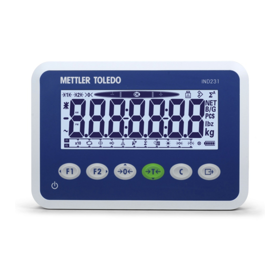
Das IND231/IND236-Terminal verwendet eine transflektive LCD-Segmentanzeige mit weißer Hintergrundbeleuchtung. Die Höhe von Hauptzeichen beträgt 40 mm. Die Frontplatte mit Anzeige und Tastenfeld ist in Abbildung 1-4 dargestellt. Die Tastenfelder des IND231- und des IND236- Terminals unterscheiden sich nur durch den Namen oben rechts im Terminal. -
Seite 108: Tasten Der Frontplatte
1.10.2. Tasten der Frontplatte Die Bedienerschnittstelle des IND231/IND236-Terminals enthält insgesamt sieben Folientasten. Die Taste zum Drucken und die fünf Waagenfunktionstasten (drei mit definierter Funktion, zwei mit konfigurierbarer Funktion) befinden sich unter der Anzeige. Die Pfeile auf den ersten vier Tasten geben die Verwendung bei der Menünavigation an. -
Seite 109: Installation
ODER TRENNEN VON VERBINDUNGEN MINDESTENS DREISSIG (30) SEKUNDEN WARTEN. WERDEN DIESE VORSICHTSMASSNAHMEN NICHT EINGEHALTEN, KANN ES ZU SACH- ODER PERSONENSCHÄDEN KOMMEN. Die Frontplatte des IND231/IND236-Terminals ist mit vier Schrauben am hinteren Teil des Gehäuses befestigt. Wenn Sie auf die Platine des Terminals zugreifen müssen, um Optionen zu installieren, eine Innenverdrahtung vorzunehmen und Schalter einzustellen, müssen Sie die... -
Seite 110: Schutzart
Plombierschraube (siehe Abbildung 2-2) mit einem 5-mm-Inbusschlüssel. Alle Schrauben sind unverlierbar und verbleiben an der hinteren Abdeckung des IND236. Plombierschraube Abbildung 2-2: Öffnen des Gehäuses – IND231 (links) und IND236 (rechts) 3. Trennen Sie den vorderen Teil vom hinteren Teil, siehe Abbildung 2-3. Abbildung 2-3: Entfernen der Abdeckung 2.2. -
Seite 111: Montage Des Terminals
Tastenfeld des Terminals einfach bedienbar ist. 2.3.1. Montage des IND231 2.3.1.1. Tischmontage Das IND231 besitzt zwei selbstklebende Gummifüße auf der Unterseite des Gehäuses (Abbildung 2-4), die ein Verrutschen des Geräts verhindern. Abbildung 2-4: IND231 – Gummifüße 2.3.1.2. Wand- & Säulenmontage Im Lieferumfang des IND231 sind eine Montagehalterung und zwei Rändelschrauben enthalten. -
Seite 112: Montage Des Ind236
Terminalhalterung mit den vor Ort bereitgestellten Elementen an der Fläche. 2.3.2. Montage des IND236 2.3.2.1. Tischmontage Für die Befestigung des IND236-Terminals auf einer ebenen Fläche kann eine optionale Tischmontagehalterung (Bestellnummer: 22021070) käuflich erworben werden. METTLER TOLEDO IND231/IND236 Installationshandbuch 30094803 08/2013... -
Seite 113: Wand- & Säulenmontage
Im Lieferumfang des IND236 ist eine Montagehalterung enthalten. Damit kann das Terminal entweder an einer Säule oder einer vertikalen Fläche befestigt werden. Mit der Halterung sind verschiedene Einstellungen möglich, siehe Abbildung 2-10. Abbildung 2-10: IND236 – Säulenmontage (links) und Wandmontage (rechts) 30094803 08/2013 METTLER TOLEDO IND231/IND236 Installationshandbuch... -
Seite 114: Installation Von Kabeln Und Anschlüssen
Stecker und Kabeldurchführungen • Zuweisung der Gehäuseöffnungen • Platinenkennung • Verdrahtungsschema der Hauptplatine • Netzstromanschluss • Anschlüsse für Ladeplatine und Akkupack • Anschluss für analoge Wägezelle • Serieller Anschluss COM1 • Verdrahtungsschema für Optionen METTLER TOLEDO IND231/IND236 Installationshandbuch 30094803 08/2013... -
Seite 115: Stecker Und Kabeldurchführungen
2.4.1. Stecker und Kabeldurchführungen Das IND231-Terminal verwendet eine Buchse entsprechend Standard IEC320 C14 und DSUB-9- Stecker für RS-232-Kommunikationsverbindungen.Kabeldurchführungen werden für Wägezellen und Optionsanschlüsse verwendet. Das IND236-Terminal ist für nasse Umgebungen geeignet. Bei der Installation von Kabeln und/oder Steckern, die in das Terminalgehäuse reichen, muss jedoch vorsichtig vorgegangen werden. So erreichen Sie einen wasserdichten Abschluss: •... -
Seite 116: Belegung Der Gehäuseöffnungen
2.4.1.1. Belegung der Gehäuseöffnungen Abbildung 2-13 zeigt die Öffnungen im IND231-Gehäuse. Abbildung 2-13: IND231-Gehäuseöffnungen Abbildung 2-14 zeigt die Öffnungen im IND236-Gehäuse und Tabelle 2-2 gibt die Belegung der einzelnen Öffnungen an. Abbildung 2-14: IND236-Gehäuseöffnungen Tabelle 2-2: Belegung von Stecker und Kabeldurchführungen... -
Seite 117: Platinenkennung
2.4.2. Platinenkennung Die Leiterplatten des IND231/IND236-Terminals sind am Platinenhalter befestigt.Die Netzanschlussplatte wird nur für das IND236 benötigt. Die Ladeplatine wird nur für Terminals benötigt, die mit einem Akkupack betrieben werden. Die Optionsplatinen werden alle an der gleichen Stelle montiert.Abbildung 2-15 zeigt die Position der einzelnen Platinen. -
Seite 118: Netzanschluss
Gerät ordnungsgemäß geerdet sein. Eine schlechte Erdung kann bei einem Kurzschluss im Gerät gefährlich sein. Eine ordnungsgemäße Erdung minimiert Störimpulse von außen. Das IND231/IND236 darf nicht die gleichen Netzleitungen wie Geräte mit starken Störimpulsen verwenden. Die richtige Erdung überprüfen Sie mit einem Leitungsmessgerät. Bei störenden Bedingungen ist möglicherweise ein eigener Stromkreis oder ein Inverter erforderlich. -
Seite 119: Anschluss Für Analoge Wägezelle
HINWEIS UM EINE BESCHÄDIGUNG DER PLATINE ODER DER WÄGEZELLE ZU VERMEIDEN, TRENNEN SIE DAS IND231/IND236-TERMINAL VOM NETZ UND WARTEN SIE MINDESTENS 30 SEKUNDEN, BEVOR SIE EIN KABEL ANSCHLIEßEN ODER LÖSEN. Die Wägezelle wird am Wägezellenstecker auf der Hauptplatine angeschlossen, siehe Abbildung 2-16. -
Seite 120: Abschirmung Der Analogen Wägezelle Und Ferritperleninstallation
Schutzkontakt des Steckers verbunden sein. Die beiden Methoden werden im Folgenden dargestellt. Bei beiden Methoden muss zur Einhaltung bestimmter Störemissionsgrenzen und zum Schutz des IND231/IND236-Terminals vor äußeren Einflüssen eine Ferritperle an dem Wägezellenkabel angebracht werden, das mit dem Terminal verbunden ist. Die Ferritperle ist beim Basisterminal enthalten. -
Seite 121: Ind231 - Anschluss Des Wägezellensteckers
Stift des Wägezellensteckers abgeschlossen werden. 1. Das Wägezellenkabel wird entsprechend Abbildung 2-20 in das Gehäuse geführt. Abbildung 2-20: Stifterdung der analogen Wägezelle und Ferritperleninstallation, IND231 Beachten Sie, dass die Abschirmung nicht durch den Ferrit bestehen. 2. Schieben Sie die Ferritperle entsprechend der Darstellung über das Wägezellenkabel. - Seite 122 5. Die Ferritperle des Terminals wird über das Kabelende geschoben, und die Adern werden mit dem Wägezellenstecker verbunden. Achten Sie auf den Farbcode der anzuschließenden Wägezellenader, Abbildung 2-19. Abbildung 2-23: Ferritperleninstallation und Gehäuseerdung des analogen Wägezellenkabels, IND231 2-14 METTLER TOLEDO IND231/IND236 Installationshandbuch...
-
Seite 123: Ind236 - Anschluss Des Wägezellensteckers
1. Das Wägezellenkabel tritt über die Kabeldurchführung entsprechend Abbildung 2-27 in das Gehäuse ein. 2. Bereiten Sie das Wägezellenkabel vor. Entfernen Sie den Außenmantel und kürzen Sie die Ader der Außenabschirmung entsprechend Abbildung 2-25. Abbildung 2-25: Wägezellenkabel mit entferntem Außenmantel, gekürzter Abschirmungsader 30094803 08/2013 METTLER TOLEDO IND231/IND236 Installationshandbuch 2-15... - Seite 124 Abbildung 2-28: Ferritperleninstallation und Gehäuseerdung des analogen Wägezellenkabels, IND236 6. Schieben Sie die Ferritperle entsprechend der Darstellung über das Wägezellenkabel. 7. Verbinden Sie die Wägezellenadern mit dem Stecker der Hauptplatine. Achten Sie auf den Farbcode der anzuschließenden Wägezellenader, Abbildung 2-19. 2-16 METTLER TOLEDO IND231/IND236 Installationshandbuch 30094803 08/2013...
-
Seite 125: Serieller Anschluss Com1
2. ADERQUERSCHNITT: MAX. 18 AWG (0,823 mm MIN. 24 AWG (0,205 mm Abbildung 2-30: IND236 – Beispiel für COM1-Anschluss 2.4.7. Verdrahtungsschema für Optionen Zu den Optionen für IND231/IND236, die einen externen Anschluss benötigen, gehören zum Beispiel: • COM2 mit getrennter Schnittstelle RS-232/422/485 •... -
Seite 126: Com2 Mit Getrennter Schnittstelle
Tabelle 2-6: Pinbelegung des getrennten seriellen Anschlusses Klemme Signale Beschreibung Pin 1 TX/RX+ RS-485 Daten A oder RS-422 Senden Daten A Pin 2 TX/RX- RS-485 Daten B oder RS-422 Senden Daten B Pin 3 RS-422 Empfangen Daten A 2-18 METTLER TOLEDO IND231/IND236 Installationshandbuch 30094803 08/2013... - Seite 127 Anschluss. Für den Anschluss an diesen Ausgang ist ein passendes externes Mini-USB-Kabel des Typs B erforderlich. Der Anschluss ist bei Nichtverwendung mit einer Schraubabdeckung verschlossen. Verbinder zur Hauptplatine Buchse für USB- Stecker (Abbildung 2-35) Abbildung 2-34: USB-Optionsplatine Abbildung 2-35: Mini-USB-Anschluss und Abdeckung 30094803 08/2013 METTLER TOLEDO IND231/IND236 Installationshandbuch 2-19...
- Seite 128 Ein Schalter auf der Platine der diskreten I/O-Schnittstelle bestimmt, ob die Eingänge aktiv oder passiv sind. Der Schalter muss vor der Verdrahtung der Eingänge ordnungsgemäß konfiguriert sein. Die Lage des Schalters und die Einstellung „aktiv/passiv“ sind in Abbildung 2-37 dargestellt. Aktiv Passiv Abbildung 2-37: Diskreter I/O-Schalter 2-20 METTLER TOLEDO IND231/IND236 Installationshandbuch 30094803 08/2013...
-
Seite 129: Aktiver Eingang
Werden die Eingänge als „passiv“ festgelegt, können andere Geräte wie SPS angeschlossen werden, um die Triggerspannung (in der Regel 12 oder 24 V–, maximal 30 V–) zum Einschalten der IND231/236-Eingänge zu liefern. Ein Beispiel für die Verdrahtung der passiven Eingänge mit +V ist in Abbildung 2-39 dargestellt. -
Seite 130: Relaisausgänge
Reinigen Sie die Stelle, an der Sie das Kapazitätsschild aufkleben möchten, von Öl oder sonstigen Verunreinigen. Entfernen Sie die Schutzfolie des Schilds und befestigen Sie es am Terminal oder an einer anderen Stelle, die entsprechend den lokalen Vorschriften zulässig ist. 2-22 METTLER TOLEDO IND231/IND236 Installationshandbuch 30094803 08/2013... -
Seite 131: Schließen Des Gehäuses
Die Plombierung muss den Zugriff auf die Konfiguration von für die Eichung wichtigen Funktionen verhindern. Details zur Plombierung des IND231/IND236-Terminals finden Sie in Abbildung 2-42. Gehen Sie wie folgt vor: 1. Stellen Sie sicher, dass die richtige Zulassungsregion im Setup-Menü unter F1.1.2 Zulassung ausgewählt wurde. - Seite 132 Abbildung 2-42: Anbringen der Plombe, IND231 (links) und IND236 (rechts) 3. Führen Sie das Ende der Drahtplombe durch die Öffnung in der Kunststoffplombe (Abbildung 2-43, links) und ziehen Sie den Draht straff. Schließen Sie dann die Plombe (Abbildung 2-43, rechts). Schneiden Sie den überstehenden Draht ab.
- Seite 133 IND231/IND236 Terminal de pesage...
- Seite 135 Terminal de pesage Services essentiels à une performance fiable Nous vous remercions d’avoir sélectionné la qualité et la précision de METTLER TOLEDO. Si vous respectez les instructions stipulées dans ce manuel pour votre nouvel équipement et confiez régulièrement l'étalonnage et la maintenance à notre équipe de service formée à l’usine, vous obtiendrez non seulement une exploitation fiable et précise, mais vous protégerez votre...
- Seite 137 à METTLER TOLEDO. Elle ne peut être recopiée ni intégralement ni partiellement sans le consentement exprès préalable écrit de METTLER TOLEDO. METTLER TOLEDO se réserve le droit d'apporter des changements au produit ou au manuel sans préavis. COPYRIGHT ®...
- Seite 138 Déclaration de conformité RoHS La plupart de nos produits appartiennent aux catégories 8 et 9 qui ne s'inscrivent pas dans le cadre de la Directive 2002/95/EG (RoHS) du 27 janvier 2003. Si nos produits sont destinés à être utilisés dans d'autres produits qui eux-mêmes dépendent de la directive RoHS, les conditions de conformité...
- Seite 139 CONSERVER ce manuel à titre de référence ultérieure. AVERTISSEMENT POUR ASSURER UNE PROTECTION SANS FAILLE CONTRE LES CHOCS ÉLECTRIQUES, BRANCHEZ LA VERSION CA DU TERMINAL DE L'IND231/IND236 À UNE PRISE CORRECTEMENT MISE À LA TERRE (MASSE). N'ENLEVEZ PAS LA BROCHE DE TERRE (MASSE).
-
Seite 140: Condition Relative À Une Mise Au Rebut Sécuritaire
BATTERIE EN DEHORS DE SA PLAGE DE TEMPÉRATURE DE 0 °C (32 °F) À 40 °C (104 °F). AVIS POUR ÉVITER D'ENDOMMAGER LA CARTE OU LE CAPTEUR, DÉCONNECTEZ L'ALIMENTATION SUR LE TERMINAL IND231/IND236 ET ATTENDEZ AU MOINS 30 SECONDES AVANT DE CONNECTER OU DE DÉCONNECTER UN FAISCEAU DE CÂBLES. AVIS TOUJOURS MANIPULER LES APPAREILS SENSIBLES À... - Seite 141 Table des matières Introduction ................. 1-1 1.1. Présentation générale de l'IND231/IND236 ........1-1 1.1.1. Caractéristiques standard ..................1-1 1.1.2. Types de terminal IND231/IND236 ............... 1-2 1.2. Utilisation dans des zones dangereuses........... 1-2 1.3. Spécifications ................1-2 1.4. Identification du modèle ..............1-4 1.5.
- Seite 142 METTLER TOLEDO IND231/IND236 Guide d'installation 30094803 08/2013...
-
Seite 143: Introduction
1.1. Présentation générale de l'IND231/IND236 1.1.1. Caractéristiques standard Concept de l'enceinte en plastique facile à manipuler pour l'IND231, enceinte robuste en • acier inoxydable pour l'IND236 Prise en charge d'une plate-forme de capteurs analogiques jusqu'à quatre capteurs de 350 •... -
Seite 144: Types De Terminal Ind231/Ind236
Types de terminal IND231/IND236 Le terminal est disponible dans les quatre versions suivantes : • Enceinte en plastique IND231, alimentation secteur (également conçu pour être utilisé avec des piles alcalines de type AA) • Enceinte en plastique IND231, alimentation par batterie Ni-MH rechargeable •... - Seite 145 Le terminal ne peut pas être utilisé dans des zones classées dangereuses en raison de l'atmosphère explosive ou combustible y régnant. Contactez un représentant METTLER TOLEDO agréé pour de plus amples informations sur les applications destinées aux zones dangereuses. Alimentation Version CA : Fonctionne entre 85 et 264 V CA, 49 à...
- Seite 146 Class III, 2 x 3000e et 6000e ; TC78351, T5976 OIML : Class III, 2 x 3000e et 6000e ; Sécurité des produits UL, cUL, CE Accessoires Support de montage mural/sur colonne ; support pour bureau METTLER TOLEDO IND231/IND236 Guide d'installation 30094756|00|08/2013...
-
Seite 147: Identification Du Modèle
1.4. Identification du modèle Le numéro de modèle, le numéro usine et le numéro de série de l'IND231/IND236 se trouvent sur la plaque signalétique du terminal. Reportez-vous à la Figure 1-1 afin de vérifier la configuration du terminal IND231/IND236 lorsqu'il quitte l'usine METTLER TOLEDO. -
Seite 148: Dimensions
1.6. Dimensions Les dimensions de l'enceinte de l'IND231/IND236 sont présentées sur les Figure 1-2 et Figure 1-3 en mm et en [po]. Figure 1-2 : Dimensions de l'enceinte de l'IND231 METTLER TOLEDO IND231/IND236 Guide d'installation 30094756|00|08/2013... -
Seite 149: Circuit Imprimé Principal
1.7. Circuit imprimé principal Le circuit imprimé principal du terminal IND231/IND236 fournit une interface aux capteurs analogiques de la bascule ainsi que le port série COM1 RS-232. Le port série COM1 RS-232 prend en charge des communications bidirectionnelles avec une vitesse maximum de 115 200 bauds. -
Seite 150: Bases De Bascules
1.8. Bases de bascules Le terminal IND231/IND236 prend en charge les bascules analogiques et fournit une tension d'excitation de 5 volts d'alimentation des capteurs analogiques. Quatre capteurs maximum de 350 Ω peuvent être alimentés par le terminal. Une connexion aux capteurs par un câble à quatre ou à six conducteurs est fournie avec des lignes de détection afin de maintenir la précision suite aux variations de résistance du câble du capteur... -
Seite 151: Affichage Et Clavier
La hauteur du caractère principal est de 40 mm. Le panneau avant comprenant l'affichage et le clavier est présenté sur la Figure 1-4. La seule différence entre les claviers de l'IND231 et de l'IND236 concerne le nom dans le coin supérieur droit du terminal. -
Seite 152: Touches Du Panneau Avant
1.10.2. Touches du panneau avant L'interface opérateur du terminal IND231/IND236 fournit un total de sept touches à membrane. La touche d'impression et les cinq touches de fonction de la balance (trois avec une fonction fixe, deux avec des fonctions configurables) sont positionnées sous l'affichage. -
Seite 153: Installation
CONSIGNES PEUT ENTRAÎNER UN ACCIDENT OU ENDOMMAGER, VOIRE DÉTRUIRE, L’ÉQUIPEMENT. Le panneau avant du terminal IND231/IND236 est verrouillé en place par quatre vis qui le fixent sur le boîtier arrière de l'enceinte. Pour accéder à la carte du terminal afin d'installer les options, connectez le câblage interne et réglez les commutateurs, et séparez le panneau avant de l'enceinte... -
Seite 154: Protection De L'environnement
Vis de plombage Figure 2-2 : Ouverture des enceintes – IND231 (à gauche) et IND236 (à droite) 3. Séparez le boîtier avant du boîtier arrière comme sur la Figure 2-3. Figure 2-3 : Démontage du couvercle 2.2. Protection de l'environnement AVERTISSEMENT L'IND231/IND236 N'EST PAS CONÇU POUR ÊTRE UTILISÉ... -
Seite 155: Montage Du Terminal
2.3.1.2. Montage mural et montage sur colonne Un support de montage et deux boutons de serrage sont inclus avec l'IND231. Ceux-ci peuvent être utilisés pour monter le terminal sur une colonne ou sur une surface verticale. 1. Utilisez les deux boutons de support afin de fixer les supports en partie inférieure du terminal comme sur la Figure 2-5. -
Seite 156: Montage De L'ind236
Si le terminal IND236 est monté sur une surface plane, un support de montage de bureau en option (Réf 22021070) est disponible à l'achat. Figure 2-8 : IND236 avec support de montage pour bureau METTLER TOLEDO IND231/IND236 Guide d'installation 30094803|00|08/2013... -
Seite 157: Installation Des Câbles Et Des Connecteurs
Installation des câbles et des connecteurs Cette section fournit des informations sur l’installation des câbles et des connecteurs sur le terminal IND231/IND236, notamment : • Connecteurs et presse-étoupes • Attribution des ouvertures de l'enceinte 30094803|00|08/2013 METTLER TOLEDO IND231/IND236 Guide d'installation... -
Seite 158: Connecteurs Et Presse-Étoupes
Connexions de câblage des options 2.4.1. Connecteurs et presse-étoupes L'IND231 utilise une prise d'alimentation standard (IEC320 C14) et des connecteurs DSUB-9 pour les communications RS-232. Les presse-étoupes sont utilisés pour les connexions des capteurs et des options. Le terminal IND236 est conçu pour supporter des environnements fortement humides. Vous devez néanmoins prendre des précautions lors de l'installation des câbles et/ou des connecteurs qui... - Seite 159 étanchéité. Le joint doit être étanche à l'eau. 2.4.1.1. Attribution des ouvertures de l'enceinte La Figure 2-13 présente les ouvertures de l'enceinte de l'IND231. Figure 2-13 : Ouvertures de l'enceinte IND231 La Figure 2-14 présente les ouvertures de l'enceinte de l'IND236 et le Tableau 2-2 indique l'attribution de chaque ouverture.
-
Seite 160: Identification De La Carte
2.4.2. Identification de la carte Toutes les cartes du terminal IND231/IND236 sont montées sur le support PCB. La carte de connexion CA n'est nécessaire que pour l'IND236. La carte de charge n'est utilisée que pour les terminaux alimentés par un bloc de batteries rechargeables. Toutes les cartes en option se montent sur le même emplacement. -
Seite 161: Connexions De L'alimentation Ca
être à l'origine d'une situation dangereuse en cas de court-circuit dans l'équipement. Une bonne masse est nécessaire afin de minimiser les impulsions électriques parasites inutiles. L'IND231/IND236 ne doit partager aucun câble d'alimentation électrique avec des équipements générant du bruit. Pour vérifier la continuité de la masse, utilisez un analyseur de circuit du commerce. -
Seite 162: Connexion À Un Capteur Analogique
Les connexions aux capteurs sont réalisées grâce aux connecteurs situés sur la carte principale, comme indiqué à la Figure 2-16. Le terminal IND231/236 a été conçu pour alimenter jusqu'à quatre capteurs de 350 ohms (soit une résistance minimum d’environ 87 ohms). Afin de confirmer que la charge du capteur pour cette installation se trouve dans les limites, la résistance totale de la balance (TSR) doit être calculée. - Seite 163 Figure 2-19 : Terminaison du capteur, Masse du châssis (en haut) et Broche de masse (en bas) Lors de l'utilisation d'un câble à quatre conducteurs normalisé, si une augmentation de la charge est accompagnée d’une diminution de l'affichage du poids, inversez les conducteurs de signalisation (+SIG et −SIG). 30094803|00|08/2013 METTLER TOLEDO IND231/IND236 Guide d'installation 2-11...
- Seite 164 1. Le câble du capteur cheminera à l'intérieur de l'enceinte, comme indiqué à la Figure 2-20. Figure 2-20 : Broche de masse du capteur analogique et installation de la ferrite, IND231 Notez que le fil de blindage ne passe pas par la ferrite.
- Seite 165 Reportez-vous au code des couleurs du câble du capteur étant connecté et à la Figure 2-19. Figure 2-23 : Installation de la ferrite du câble d'un capteur analogique avec mise à la masse sur le châssis, IND231 30094803|00|08/2013 METTLER TOLEDO IND231/IND236 Guide d'installation 2-13...
- Seite 166 2. Préparez le câble du capteur en dénudant le revêtement extérieur et en coupant le blindage extérieur comme sur la Figure 2-25. Figure 2-25 : Câble du capteur avec la gaine externe dénudée et le blindage coupé 2-14 METTLER TOLEDO IND231/IND236 Guide d'installation 30094803|00|08/2013...
- Seite 167 Figure 2-28 : Installation de la ferrite du câble d'un capteur analogique avec mise à la masse sur le châssis, IND236 6. Positionnez la ferrite sur le câble du capteur conformément aux indications. 30094803|00|08/2013 METTLER TOLEDO IND231/IND236 Guide d'installation 2-15...
-
Seite 168: Connexion Du Port Série Com1
24 AWG (0,205 mm²) MINI Figure 2-30 : Exemples de connexions COM1 de l'IND236 2.4.7. Connexions de câblage des options Les options de l'IND231/IND236 qui nécessitent une connexion externe sont les suivantes : • COM2 avec RS-232/422/485 isolés 2-16 METTLER TOLEDO IND231/IND236 Guide d'installation... - Seite 169 PIEDS (15 MÈTRES). RS-422/485 : LONGUEUR MAXIMUM DU CÂBLE : 1000 PIEDS (304 MÈTRES) SECTION DU CÂBLE : 18 AWG (0,832 mm²) MAXI 24 AWG (0,205 mm²) MINI Figure 2-33 : Signaux du port COM2 30094803|00|08/2013 METTLER TOLEDO IND231/IND236 Guide d'installation 2-17...
- Seite 170 Le port est équipé d'une protection vissable lorsqu'il n'est pas utilisé. Connecteur vers la carte principale Base pour le connecteur USB (Figure 2-35) Figure 2-34 : Carte USB en option Figure 2-35 : Protection et connecteur mini-USB 2-18 METTLER TOLEDO IND231/IND236 Guide d'installation 30094803|00|08/2013...
- Seite 171 Assurez-vous que le commutateur est correctement réglé avant de procéder au câblage vers les entrées. L'emplacement du commutateur et le positionnement actif/passif sont présentés sur la Figure 2-37. Actif Passif Figure 2-37 : Commutateur E/S discrètes 30094803|00|08/2013 METTLER TOLEDO IND231/IND236 Guide d'installation 2-19...
- Seite 172 (généralement 12 V CC ou 24 V CC, maximum 30 V CC) pour « activer » les entrées de l'IND231/236. Un exemple de câblage vers les entrées passives avec +V sur le commun est présenté sur la Figure 2-39.
-
Seite 173: Instructions De L'étiquette De Capacité
Nettoyez les traces d'huiles ou d'autres contaminants sur la zone où l'étiquette de capacité sera apposée. Détachez la pellicule protectrice de l'étiquette avant de l'apposer sur la réglette près de l'affichage ou sur un autre endroit acceptable par les règlements locaux. 30094803|00|08/2013 METTLER TOLEDO IND231/IND236 Guide d'installation 2-21... -
Seite 174: Fermeture De L'enceinte
2. Le panneau avant étant installé sur l'enceinte et les vis de fixations serrées, introduisez l'extrémité libre du fil du plomb à travers la vis de plombage de l'IND231/IND236 et à travers l'orifice du système de plombage sur l'enceinte (Figure 2-42). - Seite 175 Figure 2-42 : Installation du plomb sur l'IND231 (à gauche) et sur l'IND236 (à droite) 3. Introduisez l'extrémité du fil à travers l'orifice dans la partie en plastique du plomb (Figure 2- 43, à gauche), éliminez le mou sur le fil et refermez le système de plombage (Figure 2-43, à...
- Seite 176 2-24 METTLER TOLEDO IND231/IND236 Guide d'installation 30094803|00|08/2013...
- Seite 177 IND231/IND236 Terminale di pesata...
- Seite 179 Terminale di pesata Manutenzione necessario per prestazioni affidabili Grazie per aver scelto la qualità e la precisione di METTLER TOLEDO. Utilizzando questo nuovo dispositivo in modo appropriato, nel rispetto delle istruzioni del manuale e della regolazione e della manutenzione regolare offerti dal nostro team di assistenza addestrato in fabbrica, il funzionamento rimarrà...
- Seite 181 METTLER TOLEDO. Non può essere copiata interamente o in parte senza il consenso scritto della METTLER TOLEDO. La METTLER TOLEDO si riserva il diritto di apportare miglioramenti o modifiche al prodotto o al manuale senza preavviso. COPYRIGHT ®...
- Seite 182 Dichiarazione di conformità RoHS La maggior parte dei nostri prodotti rientrano nelle categorie 8 e 9. Queste categorie non rientrano attualmente nell’ambito della Direttiva 2002/95/EG (RoHS) del 27 gennaio 2003. Se i nostri prodotti sono intesi per essere utilizzati con altri prodotti che rientrano nell’ambito della direttiva RoHS, è necessario negoziare contrattualmente in sede separata i requisiti di conformità.
- Seite 183 CONSERVARE questo manuale per utilizzo futuro. AVVERTENZA PER UNA PROTEZIONE CONTINUA CONTRO IL RISCHIO DI SCOSSE ELETTRICHE, COLLEGARE LA VERSIONE CA DEL TERMINALE IND231/IND236 SOLO A UNA PRESA CORRETTAMENTE MESSA A TERRA. NON RIMUOVERE IL POLO DI TERRA. AVVERTENZA LA MANUTENZIONE DEL TERMINALE DEVE ESSERE ESEGUITA SOLO DA PERSONALE QUALIFICATO.
- Seite 184 IL CARICATORE BATTERIA AL DI FUORI DEL SUO INTERVALLO DI TEMPERATURA DA 0°C (32°F) A 40°C (104°F). AVVISO ONDE EVITARE DANNI ALLA CELLA DI CARICO O ALLA SCHEDA, RIMUOVERE L'ALIMENTAZIONE DAL TERMINALE IND231/IND236 E ATTENDERE ALMENO 30 SECONDI PRIMA DI COLLEGARE O SCOLLEGARE QUALUNQUE CABLAGGIO. AVVISO RISPETTARE LE PRECAUZIONI PER LA GESTIONE DEI DISPOSITIVI SENSIBILI ALLE CARICHE ELETTROSTATICHE.
- Seite 185 Indice Introduzione ................1-1 1.1. Panoramica IND231/IND236 ............1-1 1.1.1. Funzioni standard ....................1-1 1.1.2. Tipi di terminale IND231/IND236 ................1-2 1.2. Utilizzo in ambienti a rischio ............1-2 1.3. Specifiche tecniche ................ 1-2 1.4. Identificazione del modello ............. 1-4 1.5.
- Seite 186 METTLER TOLEDO Terminale IND231/IND236 Guida all'installazione 30094803 08/2013...
-
Seite 187: Introduzione
1.1. Panoramica IND231/IND236 1.1.1. Funzioni standard Design maneggevole con scocca in plastica per l’IND231 e robusta scocca in acciaio • inossidabile per l’IND236 Supporta una piattaforma con cella di carico analogica con fino a quattro celle di carico da •... -
Seite 188: Tipi Di Terminale Ind231/Ind236
1.1.2. Tipi di terminale IND231/IND236 Il terminale è disponibile nelle quattro versioni seguenti: • IND231 con scocca in plastica, alimentazione CA (anche per l’uso con pile alcaline AA) • IND231 con scocca in plastica, alimentazione a batteria ricaricabile Ni-MH •... - Seite 189 Interfaccia I/O digitale Porta I/O digitale opzionale: 2 ingressi/4 uscite Interfaccia USB Porta USB opzionale: Protocollo Ingressi seriali: comandi ASCII per CTPZ (cancellazione, tara, stampa, zero), SICS (molti comandi di livello 0 e livello 1) 30094803 08/2013 METTLER TOLEDO IND231/IND236 Guida all'installazione...
-
Seite 190: Identificazione Del Modello
1.4. Identificazione del modello Il numero di modello, numero di fabbrica e numero di serie dell'IND231/IND236 si trovano sulla piastra dei dati del terminale. Per verificare la configurazione del terminale IND231/IND236 quando lascia la fabbrica METTLER TOLEDO, fare riferimento alla Figura 1-1. -
Seite 191: Ispezione E Lista Di Controllo Dei Contenuti
Cavo di alimentazione • Borsa contenente varie parti 1.6. Dimensioni fisiche Le dimensioni fisiche della scocca del modello IND231/IND236 sono mostrate in Figura 12 e in Figura 1-3 in mm e [pollici]. Figura 1-2: Dimensioni della scocca IND231 30094803 08/2013... -
Seite 192: Pcb Principale
Una scheda di carica opzionale è inclusa nella versione alimentata con batteria ricaricabile. 1.8. Basi della bilancia I terminali IND231/IND236 supportano le basi per bilance analogiche, fornendo un'eccitazione di 5 V per alimentare le celle di carico analogiche. Il terminale può alimentare fino a quattro celle di carico da 350 Ω. -
Seite 193: Opzioni
L'altezza del carattere principale è 40 mm. Il pannello anteriore, che comprende il display e la tastiera, è raffigurato in Figura 14. L'unica differenza sulla tastiera tra IND231 e IND236 è il nome sull'angolo in alto a destra del terminale. -
Seite 194: Struttura Display
1.10.2. Tasti del pannello frontale L'interfaccia operatore del terminale IND231/IND236 dispone di un totale di sette tasti a membrana. Il tasto di stampa e i cinque tasti funzione della bilancia (tre per le funzioni fisse e due per le funzioni configurabili) sono posizionati sotto il display. -
Seite 195: Installazione
1. Per IND231, usare un giravite torx T-20 per allentare tre delle quattro viti. Usare un giravite a lama piatta per allentare la vite del sigillo, come illustrato in Figura 2-1. -
Seite 196: Protezione Ambientale
Vite per sigillo Figura 2-2: Aperture delle scocche – IND231 (a sinistra) e IND236 (a destra) 3. Separare l'alloggiamento anteriore da quello posteriore, come mostrato in Figura 2-3. -
Seite 197: Montaggio Del Terminale
2.3.1. Montaggio IND231 2.3.1.1. Montaggio su banco L'IND231 è dotato di due piedini in gomma autoadesivi (Figura 2-4) fissati sul fondo della scocca per evitare che scivoli. Figura 2-4: IND331 – Piedino in gomma 2.3.1.2. Montaggio a parete o a colonna La staffa di montaggio e i due pomelli di serraggio sono inclusi con l'IND231. -
Seite 198: Montaggio Ind236
Montaggio su banco Se il terminale IND236 viene montato su una superficie piana, è possibile acquistare una staffa per il montaggio su banco (PN: 22021070). Figura 2-8: IND236 con staffa di montaggio su banco METTLER TOLEDO IND231/IND236 Guida all'installazione 30094803 08/2013... -
Seite 199: Installazione Dei Cavi E Dei Connettori
Figura 2-11: Dimensioni staffa da parete e colonna per IND236 2.4. Installazione dei cavi e dei connettori Le informazioni per l'installazione dei cavi e dei connettori per il terminale IND231/IND236 sono fornite in questa sezione, inclusi: • Connettori e passacavi •... -
Seite 200: Connettori E Passacavi
Connessioni di cablaggio per le opzioni 2.4.1. Connettori e passacavi Il modello IND231 utilizza una presa di alimentazione standard (IEC320 C14) e connettori DSUB-9 per comunicazioni RS-232. I pressacavi sono utilizzati per i collegamenti della cella di carico e delle opzioni. -
Seite 201: Identificazione Pcb
COM1 (RS-232) Cavo cella di carico 2.4.2. Identificazione PCB Tutte le schede elettroniche del terminale IND231/IND236 sono montate sull'assieme di supporto PCB. La scheda per il collegamento CA è necessaria solo per il terminale IND236. La scheda per la 30094803 08/2013... -
Seite 202: Principali Connessioni Di Cablaggio Della Scheda
Questo è il solo modo per cambiare i parametri della bilancia su un terminale omologato. Per maggiori dettagli, fare riferimento a Entrare in modalità configurazione e Omologazione I tipo di bilancia nel Capitolo 3 della Guida del’utente, Configurazione. METTLER TOLEDO IND231/IND236 Guida all'installazione 30094803 08/2013... -
Seite 203: Collegamento Dell'alimentazione Ca
Ingresso linee CA Figura 2-17: Scheda di alimentazione Il terminale IND231 è fornito con presa standard (IEC320 C14) e cavo di alimentazione. Un cavo di linea permanentemente collegato fornisce alimentazione CA alla versione CA del terminale IND236. Il cavo di terra presenta un terminale a occhiello per il collegamento alla terra internamente (Figura 2-18). -
Seite 204: Collegamento Per Cella Di Carico Analogica
I collegamenti della cella di carico sono realizzati sul connettore della cella di carico montato sulla scheda madre, come mostrato in Figura 2-16. Il terminale IND231/236 è progettato per alimentare fino a quattro celle di carico da 350 ohm (o una resistenza minima di circa 87 ohm). Per confermare che la cella di carico per quest'installazione è... - Seite 205 2. CELLE SINGOLE A 4 CONDUTTORI: PONTICELLO DA + EXE A + SEN E 2. DIMENSIONE DEI FILI: 18 AWG (0,823 mm2) MASSIMO, 4 AWG PONTICELLO DA – EXE A – SEN SUI TERMINALI IND231/IND236 (0,205 mm2) MINIMO. 3. CELLE MULTIPLE A 4 CONDUTTORI: PONTICELLO DA + EXE A + SEN E PONTICELLO DA –...
- Seite 206 In entrambi i metodi, al fine di ottenere la conformità a determinati limiti di emissione del rumore e di proteggere l'IND231/IND236 da interferenze esterne, è necessario installare un nucleo in ferrite sul cavo della cella di carico collegata al terminale. Il nucleo in ferrite è in dotazione alla versione base del terminale.
- Seite 207 Fare riferimento al codice dei colori della cella di carico da collegare e alla Figura 2-19. Figura 2-23: Installazione della ferrite sul cavo della cella di carico analogica e messa a terra sul telaio, IND231 30094803 08/2013 METTLER TOLEDO IND231/IND236 Guida all'installazione 2-13...
- Seite 208 2. Preparare il cavo della cella di carico rimuovendo il rivestimento esterno e tagliando il filo della schermatura esterna come illustrato nella Figura 2-25. Figura 2-25: Cavo della cella di carico dopo aver rimosso la guaina esterna e aver tagliato il filo di schermatura. 2-14 METTLER TOLEDO IND231/IND236 Guida all'installazione 30094803 08/2013...
- Seite 209 Figura 2-28 (sinistra). Figura 2-28: Installazione della ferrite sul cavo della cella di carico analogica e messa a terra sul telaio, IND236 6. Posizionare la ferrite intorno al cavo cella di carico come indicato. 30094803 08/2013 METTLER TOLEDO IND231/IND236 Guida all'installazione 2-15...
-
Seite 210: Connessioni Della Porta Seriale Com1
MASSIMO 24 AWG (0,205 mm ) MINIMO. Figura 2-30: Modello di collegamento COM1 per IND236 2.4.7. Connessioni di cablaggio per le opzioni Le opzioni per IND231/IND236 che richiedono connessioni esterne comprendono: • COM2 con RS-232/422/485 isolata • Interfaccia USB 2-16... - Seite 211 RS-232: LUNGHEZZA MASSIMA DEL CAVO: 15 METRI (50 PIEDI) RS-422/485: LUNGHEZZA MASSIMA DEL CAVO: 304 METRI (1000 PIEDI) DIMENSIONI DEI FILI: 18 AWG (0,832 mm MASSIMO 24 AWG (0,205 mm ) MINIMO. Figura 2-33: Segnali porta COM2 30094803 08/2013 METTLER TOLEDO IND231/IND236 Guida all'installazione 2-17...
- Seite 212 La porta è dotata di cappuccio da avvitare quando la porta non è in uso. Connettore alla scheda madre Presa per connettore (Figura 2-35) Figura 2-34: Scheda opzionale USB Figura 2-35: Presa Mini USB con cappuccio 2-18 METTLER TOLEDO IND231/IND236 Guida all'installazione 30094803 08/2013...
- Seite 213 Un interruttore sulla scheda dell'I/O discreto seleziona gli ingressi attivi o passivi. Prima del cablaggio agli ingressi, accertarsi che l'interruttore sia impostato correttamente. La posizione dell'interruttore e il posizionamento attivo/passivo sono mostrati in Figura 2-37. Attivo Passivo Figura 2-37: Interruttore I/O discreto 30094803 08/2013 METTLER TOLEDO IND231/IND236 Guida all'installazione 2-19...
- Seite 214 2. NON LEGARE IL CABLAGGIO DI INPUT CON IL CABLAGGIO DI ALIMENTAZIONE O ALTRI CAVI AD ELEVATA ENERGIA. 3. DIMENSIONI DEI FILI: 18 AWG (0,832 mm ) MASSIMO 24 AWG (0,205 mm ) MINIMO. Figura 2-39: connessioni dell'ingresso passivo 2-20 METTLER TOLEDO IND231/IND236 Guida all'installazione 30094803 08/2013...
-
Seite 215: Istruzioni Per L'etichetta Di Capacità
Eliminare eventuali tracce d’olio o di altro sporco dalla zona sulla quale verrà applicata l’etichetta di indicazione della capacità. Staccare la parte posteriore e applicare l’etichetta sulla mascherina oppure in un’altra posizione accettabile in base alle normative locali. 30094803 08/2013 METTLER TOLEDO IND231/IND236 Guida all'installazione 2-21... -
Seite 216: Chiusura Della Scocca
La sigillatura deve evitare l'accesso alla configurazione di tutte le funzioni metrologiche significative. Per i dettagli relativi alla sigillatura del terminale IND231/IND236, fare riferimento alla Figura 2-42 e seguire questi passaggi: 1. Assicurarsi che durante la configurazione, sia stata selezionata la regione di omologazione corretta, nella sezione F1.1.2 Omologazione. - Seite 217 3. Infilare l'estremità del cavo attraverso il foro nel sigillo di plastica (Figura 2-43, sinistra), stringere affinché il filo non sia lento e far scattare il sigillo in posizione di chiusura (Figura 2-43, destra). Tagliare il filo in eccesso. Figura 2-43: Chiusura del sigillo 30094803 08/2013 METTLER TOLEDO IND231/IND236 Guida all'installazione 2-23...
- Seite 218 2-24 METTLER TOLEDO IND231/IND236 Guida all'installazione 30094803 08/2013...
- Seite 219 IND231/IND236 Terminal de pesagem...
- Seite 221 Terminal de pesagem Serviços essenciais para o desempenho confiável Parabéns por escolher a qualidade e precisão da METTLER TOLEDO. O uso adequado de seu novo equipamento de acordo com este manual e a calibração e manutenção regulares feitas por nossa equipe treinada na fábrica garante uma operação confiável e precisa, protegendo o seu...
- Seite 223 METTLER TOLEDO. Ela não pode ser copiada total ou parcialmente sem o consentimento expresso por escrito da METTLER TOLEDO. A METTLER TOLEDO reserva-se o direito de fazer melhorias ou alterações no produto e no manual sem prévio aviso.
- Seite 224 Declaração de Confo rmidade RoHS A maioria dos nossos produtos está dentro das categorias 8 e 9. Essas categorias atualmente não estão dentro do escopo da Diretiva 2002/95/EG (RoHS) de 27 de janeiro de 2003. Se nossos produtos forem ser usados em outros produtos que estejam dentro do escopo da Diretiva RoHS, os requisitos de conformidade precisam ser negociados em contratos separados.
- Seite 225 SER EFETUADOS COM O APARELHO LIGADO. SE ESTA PRECAUÇÃO NÃO FOR SEGUIDA, PODEM OCORRER LESÕES CORPORAIS E/OU DANOS MATERIAIS. ADVERTÊNCIA O TERMINAL IND231/IND236 NÃO FOI PROJETADO PARA USO EM ÁREAS CLASSIFICADAS COMO PERIGOSAS DEVIDO A ATMOSFERAS COMBUSTÍVEIS OU EXPLOSIVAS. NÃO INSTALE UM IND231/IND236 EM UM AMBIENTE EXPLOSIVO.
- Seite 226 FAIXA DE TEMPERATURA DE 0°C (32°F) A 40°C (104°F). AVISO PARA EVITAR DANOS À PLACA DE CIRCUITO IMPRESSO OU À CÉLULA DE CARGA, DESLIGUE A ALIMENTAÇÃO DO TERMINAL IND231/IND236 E AGUARDE PELO MENOS 30 SEGUNDOS ANTES DE CONECTAR OU DESCONECTAR QUALQUER CHICOTE ELÉTRICO. AVISO SIGA ESTAS PRECAUÇÕES AO MANUSEAR DISPOSITIVOS SENSÍVEIS À...
- Seite 227 Conexões Elétricas para Opcionais..............2-16 2.5. Instruções para a Etiqueta de Capacidade ........2-21 2.6. Fechamento do Gabinete ............. 2-22 2.6.1. Especificações de Torque para Fixadores de Gabinete ........... 2-22 2.7. Lacre do Gabinete ............... 2-22 30094803 08/2013 METTLER TOLEDO IND231/IND236 Manual do instalação...
- Seite 228 METTLER TOLEDO IND231/IND236 Manual do instalação 30094803 08/2013...
-
Seite 229: Introdução
Introdução ao IND231/IND236 1.1.1. Recursos Padrão Design de gabinete plástico de fácil manipulação para o IND231, gabinete de aço • inoxidável resistente para o IND236 Suporte a uma plataforma de célula de carga analógica com até quatro células de carga de •... -
Seite 230: Tipos De Terminais Ind231/Ind236
Tipos de Terminais IND231/IND236 bateria. O terminal está disponível nas seguintes quatro versões: • Gabinete plástico de IND231, alimentação CA (tabém foi projetado para uso com pilhas alcalinas AA) • Gabinete plástico do IND231, alimentação por bateria NiMH recarregável •... - Seite 231 Áreas Perigosas O terminal não pode ser operado em áreas classificadas como perigosas devido a atmosferas de combustíveis ou explosivos nessas áreas. Fale com o representante autorizado METTLER TOLEDO para obter informações sobre aplicações em áreas perigosas. Potência Versão CA: Opera a 85-264 V CA, 49-61 Hz, e inclui um cabo de energia para o país de uso.
-
Seite 232: Identificação De Modelo
1.4. Identificação de Modelo O número de modelo, o número de fábrica e o número serial IND231/IND236 estão localizados na placa de dados do terminal. Consulte a Figura 1-1 para verificar a configuração do terminal IND231/IND236 quando ele sai da fábrica da METTLER TOLEDO. -
Seite 233: Inspeção E Lista De Verificação De Conteúdo
Manual de usuário (ou CD de recursos) • Manual de instalação (ou Instruções de • Pacote de bateria (versão de bateria apenas) segurança) • • Cabo de energia Suportes de montagem (1) • Sacola de peças misturadas 30094803 08/2013 IND231/IND236 Manual do instalação METTLER TOLEDO... -
Seite 234: Dimensões Físicas
1.6. Dimensões Físicas As dimensões físicas do gabinete IND231/IND236 são exibidas na Figura 1-2 e Figura 1-3 em mm e [polegadas]. Figura 1-2: Dimensões de gabinete de IND231 IND231/IND236 Manual do instalação METTLER TOLEDO 30094803 08/2013... -
Seite 235: Placa Principal
1.7. Placa Principal A placa de circuito impresso principal IND231/IND236 fornece a interface da balança de célula de carga analógica, bem como a porta serial COM1 RS-232. A porta serial COM1 RS-232 permite comunicações bidirecionais em velocidades de até 115200 bps. Essa porta pode ser utilizada ®... -
Seite 236: Bases Da Balança
1.8. Bases da Balança O terminal IND231/IND236 oferece suporte a bases de balança analógica e fornece 5 V de excitação para promover células de carga analógicas. Até quatro células de carga de 350 Ω podem ser alimentadas pelo terminal. É fornecida uma conexão de célula de carga de quatro a seis fios, com linhas de sensor para ajudar a manter precisão à... -
Seite 237: Display E Teclado
O IND231/IND236 usa um display LCD com segmento de tipo transflectivo com backlight branca. A altura do principal caractere é 40 mm. O painel frontal, incluindo display e teclado, é mostrado na Figura 1-4. A diferença de teclado apenas entre IND231 e IND236 é o nome no canto superior direito do terminal. - Seite 238 A tecla LIGAR/DESLIGAR está localizada no canto inferior esquerdo do display. Essas teclas são usadas para entrar no menu de configuração, navegar e selecionar elementos de configuração conforme descrito no Capítulo 2 do Guia do Usuário, Operação. 1-10 IND231/IND236 Manual do instalação METTLER TOLEDO 30094803 08/2013...
-
Seite 239: Instalação
1. Para o IND231, use uma chave de fenda T-20 para prender três dos parafusos. Use uma chave de fenda para soltar o parafuso de lacre, indicado na Figura 2-1. -
Seite 240: Proteção Ambiental
COMO PERIGOSAS DEVIDO A ATMOSFERAS COMBUSTÍVEIS OU EXPLOSIVAS. NÃO INSTALE UM IND231/IND236 EM UM AMBIENTE EXPLOSIVO. O terminal IND231/IND236 foi projetado para uso industrial padrão. O IND231 foi testado e atendeu aos padrões IP54. O IND236 atende aos requisitos de IP66/IP67. -
Seite 241: Montagem Do Terminal
2.3.1.2. Montagem em Parede ou Montagem em Coluna Um suporte de montagem e dois puxadores de aperto estão incluídos no IND231. Eles podem ser utilizados para montar o terminal em uma coluna ou uma superfície vertical. 1. Use dois puxadores manuais de suporte para conectar o suporte à base do terminal, como mostrado na Figura 2-5. -
Seite 242: Montagem Do Ind236
Quando o terminal IND236 for ser montado em uma superfície plana, um suporte de montagem em mesa opcional (PN: 22021070) está disponível para compra. Figura 2-8: O IND236 com Suportes de Montagem em Mesa METTLER TOLEDO IND231/IND236 Manual do instalação 30094803 08/2013... -
Seite 243: Instalação De Cabos E Conectores
Figura 2-10: IND236 Montado em Coluna (Esquerda) e Parede (Direita) Figura 2-11: Dimensões de Suporte de Coluna e Parede do IND236 2.4. Instalação de Cabos e Conectores Informações para instalar cabos e conectores no terminal IND231/IND236 são fornecidas nesta seção, incluindo o seguinte: • Conectores e prensa-cabos •... -
Seite 244: Conectores E Prensa-Cabos
2.4.1. Conectores e Prensa-Cabos O IND231 utiliza o soquete de energia padrão (IEC320 C14) e os conectores DSUB-9 para comunicação RS-232. Prensa-cabos são utilizados para conexões de célula de carga e opcionais. O terminal IND236 foi projetado para suportar ambientes altamente úmidos. No entanto, é... - Seite 245 2.4.1.1. Atribuições de Abertura do Gabinete A Figura 2-13 mostra as aberturas no gabinete IND231. Figura 2-13: Aberturas no Gabinete IND231 A Figura 2-14 mostra as aberturas no gabinete IND236, e a Tabela 2-2 indica a atribuição de cada abertura.
-
Seite 246: Identificação Da Placa Principal
2.4.2. Identificação da Placa Principal As placas de circuito terminal IND231/IND236 são todas montadas no conjunto de suporte da placa principal. A placa de conexão CA só é necessária para o IND236. A placa de carga só é utilizada para terminais alimentados por um pacote de baterias recarregáveis. As placas opcionais são todas montadas no mesmo local. -
Seite 247: Conexão De Energia Ca
Um terra fraco pode resultar em uma condição insegura caso ocorra um curto elétrico no equipamento. Uma boa conexão terra minimiza os pulsos de ruído elétrico. O IND231/IND236 não deve compartilhar linhas de alimentação com equipamentos que gerem ruídos. Para confirmar a integridade do aterramento, use um analisador de circuito derivado comercial. -
Seite 248: Conexão Analógica Da Célula De Carga
182/600 304/1000 O terminal IND231/IND236 é projetado para oferecer suporte a células de carga de 2 mV/V e 3 mV/V no mesmo circuito. Não é preciso ter um jumper de seleção da potência nominal de saída da célula de carga. - Seite 249 Nos dois métodos, para atender a determinados limites de emissão de ruído elétrico e para proteger o IND231/IND236 de influências externas, um núcleo de ferrite deve ser instalado no cabo da célula de carga conectado ao terminal. O núcleo de ferrite é incluído no terminal básico.
- Seite 250 1. O cabo da célula de carga é direcionado para o gabinete como indicado na Figura 2-20. Figura 2-20: Instalação de Ferrite e Pino Terra da Célula de Carga Analógica, IND231 Note-se que o fio de blindagem não passar pelo ferrite.
- Seite 251 Consulte o código de cores dos fios da célula de carga sendo conectados e a Figura 2-19. Figura 2-23: Instalação da Ferrite do Cabo da Célula de Carga Analógica e do Terra do Chassi, IND231 30094803 08/2013 IND231/IND236 Manual do instalação METTLER TOLEDO...
- Seite 252 2. Prepare o cabo da célula de carga removendo a capa externa e aparando o fio de blindagem externo como mostrado na Figura 2-25. Figura 2-25: Cabo da Célula de Carga com a Blindagem Externa Removida, Fio Blindado Cortado 2-14 METTLER TOLEDO IND231/IND236 Manual do instalação 30094803 08/2013...
- Seite 253 6. Coloque a ferrite sobre o cabo da célula de carga como indicado. 7. Conecte os fios da célula de carga ao conector na placa-mãe. Consulte o código de cores dos fios da célula de carga sendo conectada, e a Figura 2-19. 30094803 08/2013 IND231/IND236 Manual do instalação METTLER TOLEDO 2-15...
-
Seite 254: Conexão De Porta Serial Com1
) MÁX. 24 AWG (0,205 mm ) MÍN. Figura 2-30: Exemplo de Conexão COM1 do IND236 2.4.7. Conexões Elétricas para Opcionais As opções para IND231/IND236 que requerem conexões externas incluem o seguinte: • COM2 com RS-232/422/485 isolada • Interface USB •... - Seite 255 Tabela 2-6: Atribuições de Pino de Porta Serial Isoladas Terminal Sinais Descrição Pino 1 TX/RX+ Dados de RS-485 A ou dados de transmissão RS-422 A Pino 2 TX/RX- Dados de RS-485 B ou dados de transmissão RS-422 B 30094803 08/2013 IND231/IND236 Manual do instalação METTLER TOLEDO 2-17...
- Seite 256 A porta é equipada com uma tampa que é aparafusada quando a porta ainda estiver em uso. Conector para Placa Princip Soquete para conect or USB (Figura 2-35) Figura 2-34: Placa de Opção USB Figura 2-35: Tampa e Soquete de Mini USB 2-18 METTLER TOLEDO IND231/IND236 Manual do instalação 30094803 08/2013...
- Seite 257 Certifique-se de que a chave seja adequadamente definida antes de fazer a fiação para as entradas. A localização da chave e o posicionamento ativo/passivo foram mostrados na Figura 2-37. Ativa Passiva Figura 2-37: Chave de E/S Discreta 30094803 08/2013 IND231/IND236 Manual do instalação METTLER TOLEDO 2-19...
- Seite 258 2. NÃO PRENDA JUNTAS A FIAÇÃO DE ENTRADA COM A FIAÇÃO DE ENERGIA OU QUALQUER OUTRO CABO DE ALTA TENSÃO. 3. TAMANHO DO FIO: 18 AWG (0,832 mm2) MÁX. 24 AWG (0,205 mm2) MÍN. Figura 2-39: Conexões de Entrada Passiva 2-20 METTLER TOLEDO IND231/IND236 Manual do instalação 30094803 08/2013...
-
Seite 259: Instruções Para A Etiqueta De Capacidade
Limpe qualquer óleo ou outros contaminantes da área onde a etiqueta de capacidade será adicionada. Retire a parte de trás da etiqueta e cole-a na estrutura ou em outro local aceitável conforme as regulamentações locais. 30094803 08/2013 IND231/IND236 Manual do instalação METTLER TOLEDO 2-21... -
Seite 260: Fechamento Do Gabinete
2. Com o painel frontal instalado no gabinete e os parafusos de fixação instalados,passe a ponta livre do lacre de fios através dos parafusos de lacre do IND231/IND236, e através do orifício no ponto de lacre do gabinete (Figura 2-42). - Seite 261 3. Passe a ponta do fio metálico através do orifício do lacre de plástico (Figura 2-43, esquerda), remova qualquer folga restante no fio e feche o lacre (Figura 2-43, direita). Corte o fio excedente. Figura 2-43: Fechamento do Lacre 30094803 08/2013 IND231/IND236 Manual do instalação METTLER TOLEDO 2-23...
- Seite 262 2-24 METTLER TOLEDO IND231/IND236 Manual do instalação 30094803 08/2013...
- Seite 264 To protect your METTLER TOLEDO product’s future: Congratulations on choosing the quality and precision of METTLER TOLEDO. Proper use according to these instructions and regular calibration and maintenance by our factory-trained service team ensure dependable and accurate operation, protecting your investment. Contact us about a METTLER TOLEDO service agreement tailored to your needs and budget.