Mettler Toledo IND246 Installationshandbuch
Weighing terminal
Vorschau ausblenden
Andere Handbücher für IND246:
- Benutzerhandbuch (268 Seiten) ,
- Installationshandbuch (275 Seiten) ,
- Kurzanleitung (256 Seiten)
Inhaltsverzeichnis
Werbung
Verfügbare Sprachen
Verfügbare Sprachen
Quicklinks
Werbung
Kapitel
Inhaltsverzeichnis

Verwandte Anleitungen für Mettler Toledo IND246


Inhaltszusammenfassung für Mettler Toledo IND246
- Seite 1 IND246 and IND246 POWERCELL Weighing Terminal...
- Seite 3 Essential Services for Dependable Performance of Your IND246 and IND246 POWERCELL Weighing Terminal Congratulations on choosing the quality and precision of METTLER TOLEDO. Proper use of your new equipment according to this Manual and regular calibration and maintenance by our factory- trained service team ensures dependable and accurate operation, protecting your investment.
-
Seite 5: Fcc Notice
Restricted Rights. Copyright 2017 METTLER TOLEDO. This documentation contains proprietary information of METTLER TOLEDO. It may not be copied in whole or in part without the express written consent of METTLER TOLEDO. METTLER TOLEDO reserves the right to make refinements or changes to the product or manual without notice. -
Seite 6: Disposal Of Electrical And Electronic Equipment
RoHS Compliance Statement. The majority of our products fall within categories 8 and 9. Those categories currently do not fall within the scope of the Directive 2002/95/EG (RoHS) of January 27, 2003. If our products are intended for use in other products which themselves fall within the scope of the RoHS Directive, compliance requirements have to be separately negotiated contractually. -
Seite 7: Warnings And Cautions
IND246 TERMINAL TO PROPERLY GROUNDED OUTLET ONLY. DO NOT REMOVE THE GROUND PRONG. WARNING DO NOT USE THE IND246 TERMINAL IN AREAS CLASSIFIED AS HAZARDOUS BECAUSE OF COMBUSTIBLE OR EXPLOSIVE ATMOSPHERES. CONTACT AN AUTHORIZED METTLER TOLEDO REPRESENTATIVE FOR INFORMATION ABOUT HAZARDOUS AREA APPLICATIONS. - Seite 8 NOTICE OBSERVE PRECAUTIONS FOR HANDLING ELECTROSTATIC SENSITIVE DEVICES.
-
Seite 9: Inhaltsverzeichnis
Main Board Wiring Connections ............. 2-13 2.4.4. PDX or GDD POWERCELL Cabling ............2-18 2.4.5. PowerDeck Connection ................. 2-30 2.4.6. Wiring Connections for Options .............. 2-31 64084463 / Rev. 03 / 12/2017 METTLER TOLEDO IND246 and IND246 POWERCELL Weighing Terminal Installation Manual... - Seite 10 2.7. SD Card Installation ............2-39 2.8. Capacity Label Instructions ..........2-39 2.9. Closing the Enclosure ............2-40 2.10. Securing the Enclosure ............2-40 METTLER TOLEDO IND246 and IND246 POWERCELL Weighing Terminal Installation Manual 64084463 / Rev. 03 / 12/2017...
-
Seite 11: Introduction
Standard applications include basic weighing, animal weighing, check weighing, counting, peak weight measurement and vehicle weighing. Whether communicating weight data to a PC or providing a serial output of data to a printer, the IND246 terminal offers solutions for a wide range of applications. -
Seite 12: Ind246 Terminal Versions
IND246 POWERCELL, AC power • IND246 POWERCELL for SL_61xD, AC power 1.2. Specifications The IND246 terminal conforms to the specifications listed in Table 1-1. Table 1-1: Terminal Specifications IND246 Specifications Enclosure Type Stainless steel, configurable as desk top or wall mount enclosure Dimensions (w ×... - Seite 13 Refer to Table 1-3 for Refer to Table 1-4 for details of the battery life for the battery powered version. Power Refer to Table 1-2 for the AC version; Table 1-3 for IND246 POWERCELL; and Table 1-4 Consumption for the battery version.
- Seite 14 Table 1-2: IND246 Power Consumption (AC Source) Input Voltage I (mA) P (W) 85V/50 Hz 110 V/50 Hz 240 V/50 Hz 264 V/50 Hz 85 V/60 Hz 110 V/60 Hz 240 V/60 Hz METTLER TOLEDO IND246 and IND246 POWERCELL Installation Manual 64084463 12/2017...
-
Seite 15: Battery Performance
P(W) 85V/50Hz 110V/50Hz 240V/50Hz 264V/50Hz 85V/60Hz 110V/60Hz 240V/60Hz 264V/60Hz Table 1-4: IND246 Average Battery Life, Analog Version Battery Life Battery Life w/o Continuous Operation Load w/Backlight Backlight 1- 350Ω cell, no options 21.5 hrs 49 hrs 1 – 350Ω cell, COM2/DIO option 12.5 hrs... -
Seite 16: Use In Hazardous Areas
1.4. Use in Hazardous Areas WARNING DO NOT USE THE IND246 TERMINAL IN AREAS CLASSIFIED AS HAZARDOUS BECAUSE OF COMBUSTIBLE OR EXPLOSIVE ATMOSPHERES. CONTACT AN AUTHORIZED METTLER TOLEDO REPRESENTATIVE FOR INFORMATION ABOUT HAZARDOUS AREA APPLICATIONS. 1.5. Inspection and Contents Checklist Verify the contents and inspect the package immediately upon delivery. -
Seite 17: Model Identification
1.6. Model Identification The IND246 and IND246 POWERCELL model number, factory number and serial number are located on the data plate of the terminal. Refer to Figure 1-1 to verify the configuration of the IND246 terminal when it left the METTLER TOLEDO factory. -
Seite 18: Physical Dimensions
1.7. Physical Dimensions The physical dimensions of the IND246 enclosure are shown in Figure 1-2 and Figure 1-3 in mm and [inches]. Figure 1-2: IND246 Enclosure Dimensions Figure 1-3: IND246 Dimensions with Brackets METTLER TOLEDO IND246 and IND246 POWERCELL Installation Manual... -
Seite 19: Main Pcb
1.8.1. SD Memory An SD Memory card is included as a standard feature of the analog version of the IND246, and is available as an option for the POWERCELL version. The card provides a medium on which to store files such as Alibi memory, transaction records in the vehicle application, IDs in the counting application and target weights in the checkweighing application. -
Seite 20: Powerdeck
Figure 1-4: IND246 POWERCELL with PowerDeck Platform 1.10. Options The following options are available for all versions of the IND246: COM2 Serial Port • One RS-232/485 isolated serial COM port COM2 and DIO (relay output) •... -
Seite 21: Discrete I/O
1.10.4. Ethernet The IND246 Ethernet option provides an RJ45 jack for connection to an Ethernet network or host device. A TCP socket connection can be made to port 1701 to transfer files or to exchange data with a PC. This port can also operate as a print client to send data to a network printer. -
Seite 22: Display And Keyboard
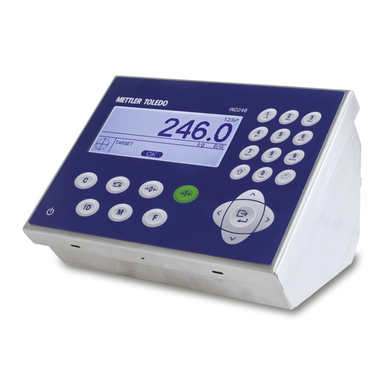
1.11.2. Front Panel Keys The IND246 terminal provides a total of 25 keys as operator interfaces. The ON/OFF key, four scale function keys and three operational keys are positioned under the display while the alpha-numeric keys are positioned to the right of the display. The print/enter key and navigation keys are located at the bottom right of the display. -
Seite 23: Installation
2.1. Opening the Enclosure The front panel of the harsh enclosure IND246 terminal is locked in place by four spring clips attached to the body of the enclosure. To access the terminal’s PCB to install options, connect internal wiring and set switches, separate the front panel from the enclosure as follows: 1. -
Seite 24: Environmental Protection
COMBUSTIBLE OR EXPLOSIVE ATMOSPHERES. DO NOT INSTALL AN IND246 INTO AN EXPLOSIVE ENVIRONMENT. The IND246 terminal is designed for heavy washdown areas. It has been tested and found to meet IP66 standards. An IP66 rating is similar to a Type 4 and a Type 6 rating. -
Seite 25: Wall Or Column Mounting With Brackets
2.3.2. Wall or Column Mounting with Brackets Two mounting brackets and four M5 screws are included with the IND246. These can be used to mount the terminal to a vertical surface. To mount the enclosure using these brackets follow these... - Seite 26 12. Loop the two AC wires through the ferrite core in the same manner noted in step 6 and secure the ferrite to the plastic adhesive pad with the new wire tie provided. METTLER TOLEDO IND246 and IND246 POWERCELL Installation Manual 64084463...
- Seite 27 2. First, the orientation of the front panel must be reversed. This involves detaching the panel and rotating the housing, and exchanging the opening used by the load cell cable: 64084463 12/2017 METTLER TOLEDO IND246 and IND246 POWERCELL Installation Manual...
- Seite 28 6. Carefully rotate the housing 180 degrees and use the nuts removed in step 4 to reattach the two grounding straps to the studs near the grip bushings (Figure 2-9). Tighten the two nuts. METTLER TOLEDO IND246 and IND246 POWERCELL Installation Manual 64084463 12/2017...
- Seite 29 5. Carefully rotate the housing 180 degrees and use the nuts removed in step 4 to reattach the two grounding straps to the studs near the grip bushings (Figure 2-11). Tighten the two nuts. 64084463 12/2017 METTLER TOLEDO IND246 and IND246 POWERCELL Installation Manual...
- Seite 30 Reattach the AC power line. 2.3.2.4. POWERCELL Model, SLB615D or SLC611D The home run cable connects to the rear of the IND246 at a 4-pin connector. Figure 2-12: 4-Pin Connector METTLER TOLEDO IND246 and IND246 POWERCELL Installation Manual 64084463...
-
Seite 31: Attaching Brackets And Mounting Terminal
Ensure that the mounting hardware is capable of supporting the weight of the terminal, which is approximately 2.6 kg (5.8 lb). Using the locally supplied hardware, secure the terminal bracket to the surface. 64084463 12/2017 METTLER TOLEDO IND246 and IND246 POWERCELL Installation Manual... -
Seite 32: Installing Cables And Connectors
2.4.1. Ferrite Core In order to meet certain electrical noise emission limits and to protect the standard IND246 from external influences, it is necessary to install a ferrite core on the load cell cable connected to the terminal. The ferrite core is included in the accessory bag supplied with the basic terminal. -
Seite 33: Cable Glands
Ensure that this seal is watertight. Cable shielding should be grounded to the inside of the IND246’s enclosure as close as possible to the entry point. Ground studs are provided on the interior of the enclosure for this purpose. - Seite 34 Table 2-2: Cable Gland Assignments Assignment Standard Front Panel Reversed Front Panel Gland Orientation Orientation AC Power Cord / None* Load Cell Cable COM1 COM2 / Digital I/O Digital I/O Ethernet / USB 2-12 METTLER TOLEDO IND246 and IND246 POWERCELL Installation Manual 64084463 12/2017...
-
Seite 35: Main Board Wiring Connections
SLC511D * Battery model assignment 2.4.3. Main Board Wiring Connections Once the IND246 terminal harsh enclosure is open, connections can be made to the terminal strips on the main board, as shown in Figure 2-19. COM1 Load cell connector... - Seite 36 2.4.3.1. AC Power Connection A permanently attached line cord supplies the AC power to the AC version of the IND246 terminal. Note that the two AC power connections are marked “L” for line (hot) and “N” for neutral as shown in Figure 2-6.
- Seite 37 Load cell connections are made to the load cell connector located on the main board as shown in Figure 2-19. The AC version of the IND246 terminal is designed to power up to ten 350-ohm load cells (or a minimum resistance of approximately 35 ohms). The battery version of the IND246 terminal is designed to power up to four 350-ohm load cells (or a minimum resistance of approximately 87 ohms).
- Seite 38 120/400 35 (10-350 Ω cells The IND246 terminal is designed to support both 2mV/V and 3mV/V load cells from the same circuitry. A load cell output rating selection jumper is not required. Figure 2-22 shows the terminal definitions for the analog load cell terminal strip. Note that when using four-wire load cells, jumpers must be placed between the +Excitation and +Sense terminals and between the −Excitation and −Sense terminals.
- Seite 39 2.4.3.4. COM1 Serial Port (POWERCELL) The COM1 port for the IND246 POWERCELL version includes connections for RS-232, RS-422 and RS-485. There is a setup parameter that must be selected to match the hardware connection used. This parameter controls how the transmit and receive lines are controlled.
-
Seite 40: Pdx Or Gdd Powercell Cabling
TO AVOID DAMAGE TO THE PCB OR LOAD CELL, REMOVE POWER FROM THE TERMINAL AND WAIT AT LEAST 30 SECONDS BEFORE CONNECTING OR DISCONNECTING ANY HARNESS. WARNING DO NOT INSTALL THE IND246 POWERCELL TERMINAL IN AREAS CLASSIFIED AS HAZARDOUS BECAUSE OF COMBUSTIBLE OR EXPLOSIVE ATMOSPHERES. CONTACT AN AUTHORIZED METTLER TOLEDO REPRESENTATIVE FOR INFORMATION ABOUT HAZARDOUS AREA APPLICATIONS. - Seite 41 2.4.4.1. Overview The IND246 POWERCELL is supplied with a gland that is compatible with the POWERCELL PDX home run cable. External grounding point POWERCELL cable gland Figure 2-27: IND246 POWERCELL Enclosure with POWERCELL Cable Gland and Grounding Point Preparing the terminal for use with POWERCELL PDX load cells involves three phases: •...
- Seite 42 5. Mark the cable jacket 1.25”/3 cm from the cut end of the exterior braided armor. Figure 2-32: Marking the Cable Jacket 6. Using a razor knife, cut carefully around the cable jacket, without cutting into the inner braided shield. 2-20 METTLER TOLEDO IND246 and IND246 POWERCELL Installation Manual 64084463 12/2017...
- Seite 43 Figure 2-34: Cutting Along the Cable Jacket 64084463 12/2017 METTLER TOLEDO IND246 and IND246 POWERCELL Installation Manual 2-21...
- Seite 44 10. Carefully cut around the inner shield at the cut mark, without cutting into its contents. Remove the cut portion of the inner shield from the cable. Figure 2-37: Removing the Inner Braided Shield 2-22 METTLER TOLEDO IND246 and IND246 POWERCELL Installation Manual 64084463 12/2017...
- Seite 45 13. Slide the plastic grommet down the cable, and fit it into the gland. Plastic grommet O-ring Figure 2-40: Plastic Grommet Positioned in Gland 14. Unbraid the individual strands of the inner braided shield. Figure 2-41: Inner Shield Unbraided 64084463 12/2017 METTLER TOLEDO IND246 and IND246 POWERCELL Installation Manual 2-23...
- Seite 46 19. Press the plastic grommet into the body of the gland, then screw the outer part over it, tightening with an adjustable wrench. The end of the cable, with the wires and foil pressed into 2-24 METTLER TOLEDO IND246 and IND246 POWERCELL Installation Manual 64084463 12/2017...
- Seite 47 Figure 2-46: Exterior Braided Armor Clamped in Place 22. The cable is now ready for installation and grounding. Figure 2-47: Cable and Cable Gland Installed in Enclosure 64084463 12/2017 METTLER TOLEDO IND246 and IND246 POWERCELL Installation Manual 2-25...
- Seite 48 2.4.4.3. External Grounding of the Cable 1. Disassemble the external grounding feature provided with the IND246 POWERCELL terminal – it includes a screw clamp and a mounting bracket. Slide the screw clamp about 8”/20 cm onto the flat braided grounding cable.
- Seite 49 4. Create a ground wire to connect the grounding stud to the ground connector on the motherboard: a. Cut the black wire removed in step 2 to 8”/20.5 cm long. 64084463 12/2017 METTLER TOLEDO IND246 and IND246 POWERCELL Installation Manual 2-27...
- Seite 50 Table 2-4: PDX Cable Color Code Terminal Description Wire Color CANH CANbus High White Not Used - Empty CANL CANbus Low Blue +24V PDX Network Power Supply PDX Network Ground Black 2-28 METTLER TOLEDO IND246 and IND246 POWERCELL Installation Manual 64084463 12/2017...
- Seite 51 10. Figure 2-55 shows the completed cabling procedure inside the IND246 POWERCELL enclosure. Ground wires connected at grounding stud Black ground wire created in step 4 Signal wires twisted together Figure 2-55: Internal POWERCELL Cable Connections Completed 2.4.4.5. Cable Lengths The terminal cannot be used with cable lengths exceeding those given in Table 2-5, or with more than 12 PDX cells.
-
Seite 52: Powerdeck Connection
2.4.5. PowerDeck Connection PowerDeck scale bases connect to the IND246 POWERCELL through an 4-pin connector installed in the housing. The connector is provided from the factory installed and with its internal connections complete. Figure A-56: PowerDeck Connector Installed in the IND246 POWERCELL... -
Seite 53: Wiring Connections For Options
Figure A-58: PowerDeck Home Run Cable 2.4.6. Wiring Connections for Options Options for the IND246 that require external connections include the following: • Ethernet TCP/IP • COM2 • COM2 with Discrete I/O • • USB with Discrete I/O Figure 2-56 shows the two option locations on the main board, where the boards mount on the connectors indicated in Figure 2-19. - Seite 54 RJ45 connector (indicated in Figure 2-58) on the option board. RJ45 connector Figure 2-61: Ethernet Connection Option Board Important: When installing the Ethernet option, adhere the Ethernet label from the kit to the enclosure near the Ethernet connector. 2-32 METTLER TOLEDO IND246 and IND246 POWERCELL Installation Manual 64084463 12/2017...
- Seite 55 See Figure 2-24 and Figure 2-61 for connection details. Terminal Signal Transmit RS-232 Receive RS-232 Logic Ground RS-485 A RS-485 data A RS-485-B RS-485 data B Figure 2-63: COM2 Port Signals 64084463 12/2017 METTLER TOLEDO IND246 and IND246 POWERCELL Installation Manual 2-33...
- Seite 56 Figure 2-65: COM2 with Discrete I/O Option Board 2.4.6.3.1. COM2 The COM2 port on the COM2/DIO option has the same connection as described in the previous COM2 section. Refer to that section for details. 2-34 METTLER TOLEDO IND246 and IND246 POWERCELL Installation Manual 64084463 12/2017...
- Seite 57 Selecting the inputs as passive (Figure 2-70) enables other devices such as PLCs to provide the trigger voltage (typically 12 VDC or 24 VDC, maximum 30 VDC) to turn the IND246 inputs “on”. An example of wiring to the passive inputs with the +V to the common is shown in Figure 2-64.
- Seite 58 The inputs can be selected as either active or passive based on the position of the slide switch on the board. The connectors are visible in Figure 2-67. 2-36 METTLER TOLEDO IND246 and IND246 POWERCELL Installation Manual 64084463 12/2017...
-
Seite 59: Pcb Switch Settings
A six position switch block (Figure 2-68) is located on the main PCB. These switches function as shown in Table 2-6. Figure 2-71: Location of Switch Block 1 on the Main PCB, Analog Version 64084463 12/2017 METTLER TOLEDO IND246 and IND246 POWERCELL Installation Manual 2-37... -
Seite 60: Discrete I/O Switch
When both SW1-2 and SW1-4 are positioned ON and AC power is applied to the terminal, a Master Reset function will be initiated. This procedure will erase all programming in the terminal and return all settings back to factory default values. This process is described in the IND246 Technical Manual, Chapter 4, Service and Maintenance. -
Seite 61: Pcb Jumper Positions
Figure 2-73: Location and Switch Settings for Discrete I/O Switch 2.6. PCB Jumper Positions There are no jumpers on the Main board or any of the option boards in the IND246 terminal. 2.7. SD Card Installation The SD memory card can be used for additional storage in the Checkweighing and Counting applications, and must be installed if the Vehicle Application is used. -
Seite 62: Closing The Enclosure
2.10. Securing the Enclosure When the IND246 terminal is used in a metrologically “approved” application, it must be protected from tampering by use of a seal. A wire security seal is included with the terminal. For sealing details of the IND246 terminal, refer to Figure 2-74 and follow these steps: 1. - Seite 63 2. With the front panel installed on the enclosure and snapped into place, thread the free end of the wire seal through either the left or right hole in the IND246 front panel, and through the hole in the retaining clip.
- Seite 64 2-42 METTLER TOLEDO IND246 and IND246 POWERCELL Installation Manual 64084463 12/2017...
- Seite 65 IND246/IND246 POWERCELL Terminal de pesaje...
- Seite 67 Terminal de pesaje Servicios esenciales para el desempeño confiable Enhorabuena por elegir la calidad y precisión de METTLER TOLEDO. El uso adecuado de su nuevo equipo siguiendo este manual, y la calibración y mantenimiento regulares por parte del equipo de servicio formado en fábrica garantizan un funcionamiento fiable y preciso, protegiendo su...
- Seite 69 METTLER TOLEDO. Esta información no puede copiarse total o parcialmente sin el consentimiento expreso por escrito de METTLER TOLEDO. METTLER TOLEDO se reserva el derecho de refinar o cambiar el producto o el manual sin previo aviso. DERECHOS DE AUTOR ®...
-
Seite 70: Requerimiento De Desecho Seguro
Enunciado referente a sustancias nocivas Nosotros no usamos directamente sustancias nocivas como asbestos, sustancias radioactivas o compuestos de arsénico. Sin embrago, compramos componentes de terceros que pueden contener algunas de estas sustancias en cantidades muy pequeñas. Requerimiento de desecho seguro En conformidad con la Directiva Europea 2002/96/EC sobre Residuos de Equipos Eléctricos y Electrónicos (WEEE), este dispositivo no puede desecharse con la basura doméstica. - Seite 71 TOMA CON CONEXIÓN A TIERRA APROPIADA. NO RETIRE EL POLO DE CONEXIÓN A TIERRA ADVERTENCIA NO USE EL TERMINAL IND246 EN ÁREAS CLASIFICADAS COMO PELIGROSAS DEBIDO A LAS ATMÓSFERAS COMBUSTIBLES O EXPLOSIVAS. COMUNÍQUESE CON UN REPRESENTANTE AUTORIZADO METTLER TOLEDO PARA PEDIR INFORMACIÓN ACERCA DE LAS APLICACIONES EN ÁREAS PELIGROSAS.
- Seite 72 AVISO NO INTENTE CARGAR LA BATERÍA SI LA TEMPERATURA DE ÉSTA ES INFERIOR A 0 °C (32 °F). NO ES POSIBLE CARGAR LA BATERÍA A ESTA TEMPERATURA O POR DEBAJO DE ESTA TEMPERATURA. NO OPERE EL CARGADOR DE BATERÍA FUERA DE SU RANGO DE TEMPERATURA DE 0 °C (32 °F) A 40 °C (104 °F). AVISO DESECHE LA BATERÍA RÁPIDAMENTE.
- Seite 73 Conexiones para cables de la tarjeta principal ............2-13 2.4.4. Cableado de la POWERCELL, PDX o GDD ............2-18 2.4.5. Conexión de PowerDeck ..................2-29 2.4.6. Conexiones de cables para otras opciones ............2-30 64084463 12/2017 METTLER TOLEDO IND246/IND246 POWERCELL Guía del instalación...
- Seite 74 Posiciones del puente de la PCB ........... 2-38 2.7. Instalación de tarjeta SD .............. 2-38 2.8. Instrucciones de la etiqueta de capacidad ........2-39 2.9. Cierre de la caja ................. 2-39 2.10. Cómo asegurar la caja ..............2-40 METTLER TOLEDO IND246/IND246 POWERCELL Guía del instalación 64084463 12/2017...
-
Seite 75: Introducción
(Secure Data, SD) amplía la memoria disponible para el almacenamiento seguro de datos cuando se requiere. • Inspección y lista de verificación del contenido A menos que se especifique lo contrario, IND246 se refiere a las versiones • Identificación del modelo analógica y POWERCELL. • Dimensiones físicas Las celdas de carga analogicas de 2 y 3 mv/V pueden usarse sin necesidad de •... -
Seite 76: Versiones Del Terminal Ind246
El programa de la herramienta de transferencia de archivos (FTT) del IND246 (incluida) • opera en una PC para intercambiar archivos de aplicación y tablas con el terminal IND246 Funciones de apagado automático y temporización de iluminación de fondo para ayudar a •... - Seite 77 10% al 95% no condensante. Áreas peligrosas El terminal IND246 no puede operarse en áreas clasificadas como peligrosas debido a la presencia de atmósferas combustibles o explosivas en esas áreas. Comuníquese con un representante autorizado METTLER TOLEDO para pedir información acerca de las aplicaciones en áreas peligrosas.
- Seite 78 III 6000e, Clase IIII 1000e; R76/2006-NL1-15.49R1 Seguridad del producto UL, cUL, CE Tabla 1-2: Consumo de energía del IND246 (fuente de CA) Voltaje de entrada I (mA) P (W) 85V / 50 Hz 110 V / 50 Hz 240 V / 50 Hz 264 V / 50 Hz METTLER TOLEDO IND246/IND246 POWERCELL Guía de instalación...
-
Seite 79: Rendimiento De La Batería
240V/50Hz 264V/50Hz 85V/60Hz 110V/60Hz 240V/60Hz 264V/60Hz Tabla 1-4: Duración promedio de la batería del IND246 analógica Duración de la batería Duración de la batería sin Carga con operación continua con iluminación de fondo iluminación de fondo 1 célula de 350Ω, sin opciones 21.5 h... -
Seite 80: Uso En Áreas Peligrosas
1.4. Uso en áreas peligrosas ADVERTENCIA NO USE EL TERMINAL IND246 EN ÁREAS CLASIFICADAS COMO PELIGROSAS DEBIDO A LAS ATMÓSFERAS COMBUSTIBLES O EXPLOSIVAS. COMUNÍQUESE CON UN REPRESENTANTE AUTORIZADO METTLER TOLEDO PARA PEDIR INFORMACIÓN ACERCA DE LAS APLICACIONES EN ÁREAS PELIGROSAS. -
Seite 81: Identificación Del Modelo
1.6. Identificación del modelo El número de modelo, número de fábrica y número de serie del IND246 se encuentran en la placa de identificación del terminal. Consulte la Figura 1-1 para verificar la configuración del terminal IND246 cuando salió de la fábrica de METTLER TOLEDO. -
Seite 82: Dimensiones Físicas
1.7. Dimensiones físicas Las dimensiones físicas de la caja del IND246 se muestran en la Figura 1-2 y en la Figura 1-3 en mm y en [pulgadas]. Figura 1-2: Dimensiones de la caja del IND246 Figura 1-3: Dimensiones del IND246 con soportes METTLER TOLEDO IND246/IND246 POWERCELL Guía de instalación... -
Seite 83: Pcb Principal
1.8. PCB principal La tarjeta de circuito impreso (PCB) principal del terminal IND246 proporciona la interfaz de la báscula para las celdas de carga analógicas, así como el puerto serial COM1 RS-232. La tarjeta principal también contiene la conexión de la entrada de energía (para alimentación de CA o batería, dependiendo del modelo), interfaz de pantalla, interfaz de teclado numérico e interruptor... -
Seite 84: Powerdeck
1.9.3. PowerDeck El IND246 POWERCELL soporta las plataformas de pesaje PowerDeck . Estas ofrecen calibración sin pesos para que la instalación sea rápida, y una guía visual para nivelar la plataforma del suelo. Figura 1-4: IND246 POWERCELL con platafaorma PowerDeck 1.10. -
Seite 85: E/S Discretas
1.10.4. Ethernet La opción Ethernet del IND246 proporciona una conexión RJ45 para conectarse a una red Ethernet o dispositivo de hospedaje. Se puede hacer una conexión TCP con el puerto 1701 para transferir archivos o intercambiar datos con una PC. Este puerto también puede operar como cliente de impresión para enviar datos a una impresora de red. -
Seite 86: Pantalla Y Teclado
Debajo de la línea del sistema está la pantalla de peso. Durante la operación de pesaje básica normal, la pantalla del terminal IND246 muestra el peso bruto o neto en el tamaño más grande de 28.5mm (1.1”). Cuando una de las aplicaciones se está ejecutando, el peso se muestra en caracteres altos de 20 mm (0.8”). - Seite 87 Capítulo 3, Configuración. 64084463 12/2017 METTLER TOLEDO IND246/IND246 POWERCELL Guía de instalación 1-13...
- Seite 88 1-14 METTLER TOLEDO IND246/IND246 POWERCELL Guía de instalación 64084463 12/2017...
-
Seite 89: Instalación
2.1. Apertura de la caja El panel frontal de la caja para ambientes adversos del terminal IND246 está fijado mediante seis sujetadores de resorte fijos en el cuerpo de la caja. Para tener acceso a la PBC del terminal para instalación de opciones, conectar el cableado interno y colocar interruptores, separe el panel frontal... -
Seite 90: Protección Ambiental
Figura 2-2: Retiro de la cubierta 2.2. Protección ambiental ADVERTENCIA EL TERMINAL IND246 NO ESTÁ DISEÑADO PARA USARSE EN ÁREAS CLASIFICADAS COMO PELIGROSAS DEBIDO A LAS ATMÓSFERAS COMBUSTIBLES O EXPLOSIVAS. NO INSTALE EL IND246 EN UN AMBIENTE EXPLOSIVO. METTLER TOLEDO IND246/IND246 POWERCELLGuía del usuario... -
Seite 91: Montaje Del Terminal
2.3.1. Montaje en escritorio Cuando el terminal IND246 se va a colocar en una superficie plana, se deben colocar las cuatro patas de goma auto-adheribles (incluidas con el terminal) en la parte inferior para evitar que se deslice. Encuentre las cuatro patas de goma, quite el papel protector del adhesivo y presione una pata en cada esquina de la parte inferior de la caja como se muestra en la Figura 2-3. - Seite 92 Figura 2-4: Preparación para separar el panel frontal 3. Desconecte el conector de CA de entrada de la tarjeta principal del IND246, observe la orientación de los cables negro y blanco, afloje los dos tornillos pequeños que sujetan los cables en su lugar y desconecte los cables.
- Seite 93 Figura 2-7. 2. Primero, la orientación del panel frontal debe invertirse. Esto implica separar el panel y girar la caja e intercambiar las aberturas que use el cable de la célula de carga: 64084463 12/2017 METTLER TOLEDO IND246/IND246 POWERCELLGuía del usuario...
- Seite 94 6. Gire con cuidado la caja 180 grados y vuelva a conectar las dos cintas de conexión a tierra en los dos pernos cerca de los manguitos de sujeción (Figura 2-9) con las dos tuercas retiradas en el paso D. Apriete las dos tuercas. METTLER TOLEDO IND246/IND246 POWERCELLGuía del usuario 64084463 12/2017...
- Seite 95 5. Gire con cuidado la caja 180 grados y vuelva a conectar las dos cintas de conexión a tierra en los dos pernos cerca de los manguitos de sujeción (Figura 2-11) con las dos tuercas retiradas en el paso D. Apriete las dos tuercas. 64084463 12/2017 METTLER TOLEDO IND246/IND246 POWERCELLGuía del usuario...
- Seite 96 Reconecte la línea de corriente alterna. 2.3.2.4. POWERCELL Model, SLB615D or SLC611D Las bases de pesaje PowerDeck se conectan al IND246 POWERCELL mediante un conector de 4 clavijas instalado en el armazón. El conector viene instalado de fábrica y con sus conexiones internas completas.
-
Seite 97: Fijación De Los Soportes Y Montaje De La Terminal
Asegúrese de que los accesorios de montaje puedan soportar el peso del terminal, que es aproximadamente de 2.6 kg (5.8 lb). Monte el soporte del terminal en la pared con los accesorios que compre. 64084463 12/2017 METTLER TOLEDO IND246/IND246 POWERCELLGuía del usuario... -
Seite 98: Instalación De Cables Y Conectores
2.4.1. Núcleo de ferrita Para cumplir con ciertos límites de emisiones de ruido eléctrico y para proteger el IND246 de interferencias externas, es necesario instalar un núcleo de ferrita en el cable de la célula de carga conectado al terminal. El núcleo de ferrita se incluye con el terminal básico. -
Seite 99: Casquillos Para Cables
Asegúrese de que este sello sea hermético. El blindaje del cable debe estar conectado a tierra en la parte interna de la caja del IND246 lo más cerca posible al punto de entrada. Se proporcionan tornillos de conexión a tierra en el interior de la caja para este propósito. - Seite 100 Cordón de corriente alterna / Ninguno* Cable de la célula de carga COM1 COM2 E/S digitales E/S digitales / Ethernet / USB Cable de la célula de carga Cordón de corriente alterna / Ninguno* 2-12 METTLER TOLEDO IND246/IND246 POWERCELLGuía del usuario 64084463 12/2017...
-
Seite 101: Conexiones Para Cables De La Tarjeta Principal
Conector opción 1 Interruptores Conector opción 2 Figura 2-19: Conexiones de la tarjeta principal del IND246, modelo para corriente alterna Conector de la célula de carga Interruptores Conector de la batería Figura 2-20: Conexiones de la tarjeta principal del IND246, modelo para batería... - Seite 102 Un cordón de línea permanente fijo alimenta corriente alterna a la caja para ambientes adversos de la versión de corriente alterna del terminal IND246. Observe que las conexiones de corriente alterna están marcadas “L” para línea (energizada) y “N” para neutro como se muestra en la Figura 2-6.
- Seite 103 Número de células de carga Compruebe que la TSR de la red de trabajo de las células de carga a ser conectada al IND246 sea mayor que los mínimos indicados anteriormente antes de conectar las células de carga. Si la resistencia está...
- Seite 104 El puerto COM1 incluye conexiones para RS-232, RS-422 y RS-485. Hay un parámetro de colocación que se debe seleccionar para hacer coincidir la conexión del equipo que se use. Este parámetro controla la forma como se controlan las líneas de transmisión y recepción. 2-16 METTLER TOLEDO IND246/IND246 POWERCELLGuía del usuario 64084463 12/2017...
- Seite 105 último nodo. La resistencia de terminación debe cumplir con la impedancia característica de la línea de transmisión, aproximadamente 120 ohmios. Esta resistencia de terminación se requiere cuando se conectan módulos ARM100 al puerto. 64084463 12/2017 METTLER TOLEDO IND246/IND246 POWERCELLGuía del usuario 2-17...
-
Seite 106: Cableado De La Powercell, Pdx O Gdd
REPRESENTANTE AUTORIZADO METTLER TOLEDO PARA PEDIR INFORMACIÓN ACERCA DE LAS APLICACIONES EN ÁREAS PELIGROSAS. 2.4.4.1. Presentación El IND246 POWERCELL se entrega con un casquillo que es compatible con el cable de conexión de la POWERCELL PDX. Punto de conexión a... - Seite 107 4. Recorte el blindaje trenzado exterior hasta la marca de corte, y remueva los alambres dispersos del corte. Figura 2-31: Blindaje trenzado exterior recortado 5. Marque el forro del cable 1.25”/3 cm desde el extremo cortado del blindaje trenzado exterior. 64084463 12/2017 METTLER TOLEDO IND246/IND246 POWERCELLGuía del usuario 2-19...
- Seite 108 Figura 2-34: Corte a lo largo del forro del cable 8. Separe el forro cortado de la protección trenzada interna hasta el corte hecho en el paso 6. 2-20 METTLER TOLEDO IND246/IND246 POWERCELLGuía del usuario 64084463 12/2017...
- Seite 109 Figura 2-37: Retiro de la protección trenzada interna 11. Destornille la parte externa del casquillo para el cable POWERCELL del terminal y desarme la abrazadera del cable. Coloque las abrazaderas y tornillos aparte en un lugar seguro. 64084463 12/2017 METTLER TOLEDO IND246/IND246 POWERCELLGuía del usuario 2-21...
- Seite 110 15. Pliegue las hebras individuales de la protección trenzada interna sobre el anillo de plástico. Las hebras individuales deberán distribuirse de manera uniforme alrededor de la superficie externa del anillo de plástico. 2-22 METTLER TOLEDO IND246/IND246 POWERCELLGuía del usuario 64084463 12/2017...
- Seite 111 19. Presione el anillo de plástico hacia dentro del cuerpo del casquillo, luego enrosque la parte externa sobre él y apriete con una llave ajustable. El extremo del cable, con los alambres y protección metálica presionados dentro del casquillo, deben quedar como se muestra en la 64084463 12/2017 METTLER TOLEDO IND246/IND246 POWERCELLGuía del usuario 2-23...
- Seite 112 Figura 2-46: Blindaje trenzado exterior sujetado con la abrazadera 22. El cable está listo ahora para instalarse y conectarse a tierra. Figura 2-47: Cable y casquillo del cable instalados en la caja 2-24 METTLER TOLEDO IND246/IND246 POWERCELLGuía del usuario 64084463 12/2017...
- Seite 113 2.4.4.3. Conexión a tierra externa del cable 1. Desarme la pieza de conexión a tierra externa que se proporciona con el terminal IND246 POWERCELL; incluye una abrazadera con tornillo y un soporte de montaje. Deslice la abrazadera con tornillo aproximadamente 8”/20 cm sobre el cable de conexión a tierra trenzado plano.
- Seite 114 Nota: no deseche el cable negro cortado en este paso. 3. Termine los cables torcidos con el terminal de argolla proporcionado. Figura 2-53: Terminación del cable de conexión a tierra 2-26 METTLER TOLEDO IND246/IND246 POWERCELLGuía del usuario 64084463 12/2017...
- Seite 115 Alimentación de energía de +24 V Rojo la red PDX TIERRA Tierra de la red PDX Negro 10. La Figura 2-55 muestra el procedimiento de cableado completado dentro de la caja del IND246 POWERCELL. 64084463 12/2017 METTLER TOLEDO IND246/IND246 POWERCELLGuía del usuario 2-27...
- Seite 116 12 celdas PDX. Tabla 2-5: Longitudes máximas del cable PDX Cable total celda a celda Cable de conexión Cantidad de (metros/pies) (metros/pies) celdas PDX 130/426 300/984 < 12 2-28 METTLER TOLEDO IND246/IND246 POWERCELLGuía del usuario 64084463 12/2017...
-
Seite 117: Conexión De Powerdeck
2.4.5. Conexión de PowerDeck Las bases de pesaje PowerDeck se conectan al IND246 POWERCELL mediante un conector de 4 clavijas instalado en el armazón. El conector viene instalado de fábrica y con sus conexiones internas completas. Figura 2-56: Conector de PowerDeck instalado en el IND246 POWERCELL... -
Seite 118: Conexiones De Cables Para Otras Opciones
Figura 2-58: Cable central de PowerDeck 2.4.6. Conexiones de cables para otras opciones Las opciones disponibles para el terminal IND246 que requieren conexiones externas incluyen las siguientes: • Ethernet TCP/IP • COM2 • COM2 con E/S discretas • • USB con E/S discretas 2-30 METTLER TOLEDO IND246/IND246 POWERCELLGuía del usuario... - Seite 119 Las secciones siguientes describen conexiones para cada una de las opciones. Figura 2-59: Ubicaciones de las tarjetas opcionales USB / DIO COM2 COM2 / DIO Ethernet Figura 2-60: Ubicaciones de las tarjetas opcionales 64084463 12/2017 METTLER TOLEDO IND246/IND246 POWERCELLGuía del usuario 2-31...
- Seite 120 Figura 2-64 para los detalles de la conexión. Terminal Señal Transmisión RS-232 Recepción RS-232 Tierra lógica RS-485 A RS-485 Datos A RS-485 B RS-485 Datos B Figura 2-63: Señales del puerto COM2 2-32 METTLER TOLEDO IND246/IND246 POWERCELLGuía del usuario 64084463 12/2017...
- Seite 121 Figura 2-65: Tarjeta opcional COM2 con E/S discretas 2.4.6.3.1. COM2 El puerto COM2 en la tarjeta opcional COM2/DIO tiene la misma conexión que la descrita en la sección anterior COM2. Consulte los detalles en esa sección. 64084463 12/2017 METTLER TOLEDO IND246/IND246 POWERCELLGuía del usuario 2-33...
- Seite 122 CABLES DE ENERGÍA U OTROS CABLES DE ALTA ENERGÍA. 3. TAMAÑO DEL CABLE: 18 AWG (0.832 mm ) MÁXIMO 24 AWG (0.205 mm ) MÍNIMO Figura 2-67: Conexiones de entradas pasivas 2-34 METTLER TOLEDO IND246/IND246 POWERCELLGuía del usuario 64084463 12/2017...
- Seite 123 Las entradas pueden seleccionarse como activas o pasivas con base en la posición del interruptor deslizante en la tarjeta. En la Figura 2-70 se observan los conectores. 64084463 12/2017 METTLER TOLEDO IND246/IND246 POWERCELLGuía del usuario 2-35...
-
Seite 124: Posiciones Del Interruptor De La Pcb
En la tarjeta principal se encuentra un bloque de interruptores de seis posiciones (Figura 2-71). Estos interruptores funcionan como se muestra en la Tabla 2-6. Figura 2-71: Ubicación del bloque de interruptores 1 en la PCB principal, version analogical 2-36 METTLER TOLEDO IND246/IND246 POWERCELLGuía del usuario 64084463 12/2017... - Seite 125 Este procedimiento borra toda la programación en el terminal y regresa todos los valores a los de fábrica. Este proceso se describe en el Manual técnico del IND246, Capítulo 4, Servicio y mantenimiento. 64084463 12/2017 METTLER TOLEDO IND246/IND246 POWERCELLGuía del usuario...
-
Seite 126: Interruptor De E/S Discretas
2-74 muestra la instalación de la tarjeta SD en el conector en la orilla de la tarjeta principal del IND246. Figura 2-74: Inserción de una tarjeta SD en el conector SD (izquierda); tarjeta SD instalada (derecha) 2-38 METTLER TOLEDO IND246/IND246 POWERCELLGuía del usuario 64084463 12/2017... -
Seite 127: Instrucciones De La Etiqueta De Capacidad
2. Presione con firmeza en cada una de las cuatro esquinas de la tapa frontal en secuencia hasta que cada pinza de las esquinas se inserte en su lugar haciendo un ruido. 64084463 12/2017 METTLER TOLEDO IND246/IND246 POWERCELLGuía del usuario 2-39... -
Seite 128: Cómo Asegurar La Caja
2. Con el panel frontal instalado en la caja e insertado en su lugar, inserte el extremo libre del sello de alambre a través del orificio izquierdo o derecho en el panel frontal del IND246 y a través del orificio en la pinza de retención. - Seite 129 IND246/IND246 POWERCELL Wägeterminal...
-
Seite 131: Wichtige Services Zur Gewährleistung Einer Zuverlässigen Performance
Wägeterminal Wichtige Services zur Gewährleistung einer zuverlässigen Performance Herzlichen Glückwunsch zu Ihrer Wahl der Qualität und Präzision von METTLER TOLEDO. Der ordnungsgemässe Gebrauch Ihres neuen Geräts gemäss dieses Handbuchs sowie die regelmäβige Kalibrierung und Wartung durch unser im Werk geschultes Serviceteam gewährleisten den zuverlässigen und genauen Betrieb und schützen somit Ihre Investition. -
Seite 133: Fcc-Mitteilung
© METTLER TOLEDO 2017 Dieses Handbuch darf ohne die ausdrückliche schriftliche Genehmigung von METTLER TOLEDO weder ganz noch teilweise in irgendeiner Form oder durch irgendwelche Mittel, seien es elektronische oder mechanische Methoden, einschließlich Fotokopieren und Aufzeichnen, für irgendwelche Zwecke reproduziert oder übertragen werden. - Seite 134 RoHS Erklärung zur Vorschrifteneinhaltung Die Mehrheit unserer Produkte gehört den Kategorien 8 und 9 an. Diese Kategorien fallen derzeit nicht in den Geltungsrahmen der Direktive 2002/95/EG (RoHS) vom 27. Januar 2003. Wenn unsere Produkte planungsweise in anderen Produkten zur Anwendung kommen sollen, die in den Geltungsrahmen der RoHS-Direktive fallen, müssen die Pflichten zur Einhaltung dieser Vorschriften separat vertraglich festgelegt werden.
-
Seite 135: Vorsichtsmassnahmen
ORDNUNGSGEMÄSS GEERDETE STECKDOSE ANSCHLIESSEN. DEN ERDUNGSSTIFT NICHT ENTFERNEN. ACHTUNG DAS IND246-TERMINAL DARF NICHT IN BEREICHEN VERWENDET WERDEN, DIE AUFGRUND ENTZÜNDLICHER ODER EXPLOSIVER UMGEBUNGEN ALS EXPLOSIONSGEFÄHRDET EINGESTUFT WURDEN. WENDEN SIE SICH AN EINEN BEFUGTEN VERTRETER VON METTLER TOLEDO, WENN SIE INFORMATIONEN ÜBER ANWENDUNGEN IN EXPLOSIONSGEFÄHRDETEN BEREICHEN BENÖTIGEN. -
Seite 136: Anforderungen Der Sicheren Entsorgung
HINWEIS NICHT VERSUCHEN, DEN AKKU AUFZULADEN, WENN DIE AKKUTEMPERATUR UNTER 0 °C (32 °F) LIEGT. EIN AUFLADEN BEI ODER UNTERHALB DIESER TEMPERATUR IST NICHT MÖGLICH. DAS AKKULADEGERÄT NICHT AUSSERHALB DES TEMPERATURBEREICHS VON 0 °C (32 °F) BIS 40 °C (104 °F) BETREIBEN. HINWEIS ABGENUTZTE AKKUS ORDNUNGSGEMÄSS ENTSORGEN. - Seite 137 Inhaltsverzeichnis Einleitung ..................1-1 1.1. IND246 – Überblick ..............1-1 1.1.1. Standardfunktionen ....................1-1 1.1.2. IND246-Terminalversionen ................... 1-2 1.2. Technische Daten ................. 1-3 1.3. Akkuleistung ................. 1-6 1.4. Verwendung in explosionsgefährdeten Bereichen ......1-6 1.5. Inspektion und Prüfliste für Inhalt ............ 1-6 1.6.
- Seite 138 Diskreter I/O-Schalter ..................2-39 2.6. Positionen der Platinendrahtbrücken ..........2-39 2.7. Installation der SD-Karte .............. 2-39 2.8. Anweisungen für Kapazitätsaufkleber ..........2-40 2.9. Schließen des Gehäuses .............. 2-40 2.10. Sichern des Gehäuses ..............2-41 METTLER TOLEDO IND246/IND246 POWERCELL Installationshandbuch 64084463 12/2017...
-
Seite 139: Einleitung
Bereichen (SD-) Speichertechnologie kann der verfügbare Datenspeicher nach Bedarf erweitert • Pflicht der sicheren werden. Entsorgung Sofern nicht anders angegeben, bezieht sich IND246 sowohl auf die analoge als • Inspektion und Prüfliste für auch auf die POWERCELL-Version. Inhalt • Modellkennzeichnung Sowohl 2-mV/V- als auch 3-mV/V analoge Wägezellen werden unterstützt, ohne dass... -
Seite 140: Ind246-Terminalversionen
• ® Speicherkarte oder InSite SL PC-Tool (im Lieferumfang) Das METTLER TOLEDO IND246 File Transfer Tool (FTT) ist ein Hilfsprogramm auf einem PC, • das Anwendungsdateien und Tabellen mit einem Terminal IND246 austauscht. Das Programm ist auf de CD-ROM enthalten Automatische Abschaltung und Timeout für Hinterleuchtung tragen beim Akkumodell zum... -
Seite 141: Technische Daten
1.2. Technische Daten Das IND246-Terminal erfüllt die in Tabelle 1-1 aufgeführten technischen Daten. Tabelle 1-1: Technische Daten zum Terminal Technische Daten zum IND246 Gehäusetyp Edelstahl, als Tischmodell oder Gehäuse zur Wandmontage konfigurierbar Abmessungen (B × H × T) 230 mm x 146 mm x 165 mm (9 in. x 5,75 in. x 6,5 in.) - Seite 142 USA: : NTEP Klasse III/IIIL - 10,000d; Cert. #11-040 Kanada: Klasse III - 10,000d; Klasse IIIHD - 20,000d; AM-5819 Europa: Klasse III 6000e, Klasse IIII 1000e; TC7918, T8426 OIML: Klasse III 6000e, Klasse IIII 1000e; R76/2006-NL1-15.49R1 Produktsicherheit UL, cUL, CE METTLER TOLEDO IND246/IND246 POWERCELL Installationshandbuch 64084463 12/2017...
- Seite 143 85 V/60 Hz 110 V/60 Hz 240 V/60 Hz 264 V/60 Hz Die dargestellten Werte gelten mit installierter interner COM2/DIO-Option und Ethernet-Option sowie einem Wägezelleneingang mit 8 x 350Ω-Wägezellen. Tabelle 1-3: Durchschnittliche IND246-Akkulebensdauer, POWERCELL Version Eingangsspannung I(mA) P(W) 85V/50Hz 110V/50Hz...
-
Seite 144: Akkuleistung
1.4. Verwendung in explosionsgefährdeten Bereichen ACHTUNG DAS IND246-TERMINAL DARF NICHT IN BEREICHEN VERWENDET WERDEN, DIE AUFGRUND ENTZÜNDLICHER ODER EXPLOSIVER UMGEBUNGEN ALS EXPLOSIONSGEFÄHRDET EINGESTUFT WURDEN. WENDEN SIE SICH AN EINEN BEFUGTEN VERTRETER VON METTLER TOLEDO, WENN SIE INFORMATIONEN ÜBER ANWENDUNGEN IN EXPLOSIONSGEFÄHRDETEN BEREICHEN BENÖTIGEN. -
Seite 145: Modellkennzeichnung
1.6. Modellkennzeichnung Modellnummer, Werksnummer und Seriennummer des IND246 befinden sich auf dem Datenschild des Terminals. Siehe Abbildung 1-1 zur Konfigurations-verifizierung des IND246-Terminals bei Verlassen des METTLER TOLEDO-Werks. Abbildung 1-1: IND246-Konfigurationstabelle 64084463 12/2017 METTLER TOLEDO IND246/IND246 POWERCELL Installationshandbuch... -
Seite 146: Abmessungen
1.7. Abmessungen Die Abmessungen des IND246-Gehäuses sind in Abbildung 1-1 und Abbildung 1-3 in mm und [Zoll] dargestellt. Abbildung 1-2: IND246-Gehäuseabmessungen Abbildung 1-3: IND246-Abmessungen mit Halterungen METTLER TOLEDO IND246/IND246 POWERCELL Installationshandbuch 64084463 12/2017... -
Seite 147: Hauptplatine
Platine angebracht. Außerdem sind für die Optionsplatinen Bussteckanschlüsse vorhanden. 1.8.1. SD-Speicherkarte Die SD-Speicherkarte ist standardmäßig im Lieferumfang des analogen Modells IND246 enthalten und optional für die POWERCELL-Version erhältlich. Auf diese Karte können Sie Dateien wie den Alibispeicher, die Transaktionsdatensätze in der Fahrzeuganwendung, IDs der Zählanwendung und Zielwertgewichte in der Prüfwägeanwendung speichern. -
Seite 148: Powerdeck
Kalibrierung ohne Testgewichte zur schnellen Installation sowie durch eine visuelle Anleitung zur Nivellierung der Bodenplattform aus. Abbildung 1-4: IND246 POWERCELL mit PowerDeck-Plattform 1.10. Optionen Für das IND246 sind folgende Optionen erhältlich: Serieller Port COM2 • • Ein serieller RS-232/485-COM-Port COM2 und DIO (Relaisausgang) •... -
Seite 149: Serieller Port Com2
Ausgabe an eine Anzeigetafel oder an eine Remote-Anzeige gesendet wird. 1.10.2. Diskrete I/O Die Option Diskrete I/O-Schnittstelle wird nur von der analogen Version des Terminals IND246 unterstützt. Die diskrete I/O-Schnittstellenoption bietet Schwachstromrelaisausgänge. Die Relaiskontakte schalten bis zu 30 Volt DC oder 250 Volt AC bei 1 A. -
Seite 150: Display Und Tastatur
Konfiguration in Setup in diesem Bereich angezeigt werden. Unter der Systemzeile befindet sich die Gewichtsanzeige. Während eines normalen, einfachen Wägevorgangs erscheint auf dem Display des IND246-Terminals das Brutto- oder Nettogewicht in der größeren Anzeigegröße von 28,5 mm (1,1 in.). Wenn eine der Anwendungen ausgeführt wird, erscheint das Gewicht in 20 mm (0,8 in.) hohen Zeichen. -
Seite 151: Installation
2.1. Öffnen des Gehäuses Die Vorderplatte des Gehäuses für raue Umgebungen des IND246-Terminals ist mit sechs Federklammern an Ort und Stelle verriegelt, die am Gehäusekörper befestigt sind. Damit Sie zum Installieren von Optionen, Anschließen von internen Verdrahtungen und Einstellen von Schaltern auf die Platine des Terminals zugreifen können, trennen Sie die Vorderplatte wie folgt vom Gehäuse:... -
Seite 152: Umgebungsschutz
ODER EXPLOSIVER UMGEBUNGEN ALS EXPLOSIONSGEFÄHRDET EINGESTUFT WURDEN. EIN IND246 DARF NICHT IN EINER EXPLOSIONSGEFÄHRDETEN UMGEBUNG INSTALLIERT WERDEN. Das IND246-Terminal wurde für raue Spritzwasserumgebungen entwickelt. Es wurde geprüft und entspricht den IP66-Normen. Die Schutzart IP66 ist einer Schutzart vom Typ 4 und Typ 6 ähnlich. -
Seite 153: Montage Mit Halterungen
2.3.1.1. Tischmontage Wenn das IND246-Terminal auf einer flachen Fläche aufgestellt wird, sollten die im Lieferumfang des Terminals enthaltenen vier selbsthaftenden Gummifüße an der Unterseite des Gehäuses befestigt werden, um ein Rutschen zu verhindern. Machen Sie die vier Gummifüße ausfindig, ziehen das Schutzpapier vom Klebstoff ab und drücken die Füße jeweils auf die Ecken an der Unterseite... - Seite 154 Erdungsbolzen befestigt Abbildung 2-4: Vorbereitung auf das Lösen der Vorderplatte 3. Trennen Sie den Zuführungsstrom-Anschlussstecker von der IND246-Hauptplatine, merken Sie sich die Ausrichtung des schwarzen und weißen Drahts, lösen Sie die zwei kleinen Schrauben, mit denen die Drähte befestigt sind, und trennen Sie die Drähte ab.
- Seite 155 Gehäuse, gedreht Stromdraht umpositioniert Erdungsbänder/Scharniere wieder angeschlossen Abbildung 2-5: Gehäuse umgekehrt 14. Verbinden Sie die schwarze/braune sowie die weiße/blaue Netzkabelader mit der Terminalschraube auf der Hauptplatine (siehe Abbildung 2-6). Abbildung 2-6: Abschluss des Netzstromdrahtes 64084463 12/2017 METTLER TOLEDO IND246/IND246 POWERCELL Installationshandbuch...
- Seite 156 5. Entfernen Sie den Wägezellen-Kabelstutzen von der Rückseite des Gehäuses und bauen Sie ihn in die Öffnung derselben Größe auf der anderen Seite des Gehäuses wieder ein (wo sich der Netzstromkabelstutzen im Netzstrommodell befand). Ziehen Sie den Stutzen auf 2 N-m (18 lbf- in) an. METTLER TOLEDO IND246/IND246 POWERCELL Installationshandbuch 64084463 12/2017...
-
Seite 157: Powercell Modell, Pdx Oder Gdd
3. Lösen und entfernen Sie die zwei Muttern, mit denen die zwei Scharnier-/ Erdungsbänder befestigt sind, die die Vorderplatte mit dem hinteren Gehäuse verbinden. 4. Schneiden Sie den Kabelbinder aus Nylon durch, mit dem der Ferritkern auf den Netzstromdrähten mit dem Klebepolster aus Kunststoff befestigt ist. 64084463 12/2017 METTLER TOLEDO IND246/IND246 POWERCELL Installationshandbuch... -
Seite 158: Befestigung Der Halterungen Und Montage
Terminals. Schließen Sie das Netzkabel wieder an. 2.3.2.4. POWERCELL-Modeld, SLB615D oder SLC611D Das Hauptkabel wird an der Rückseite des IND246 über einen 4-poligen Stecker angeschlossen. Der Stecker ist werkseitig installiert und die internen Anschlüsse sind vollständig. Figure 2-1: 4-poligen Stecker 2.3.3. - Seite 159 Terminals enthalten. Sie müssen lokal bereitgestellt werden. Es muss sichergestellt werden, dass die Befestigungsmittel das Gewicht des Terminals, das ca. 2,6 kg (5,8 lb) beträgt, abstützen können. Die Terminalhalterung mit den lokal bereitgestellten Befestigungsmitteln an der Oberfläche befestigen. 64084463 12/2017 METTLER TOLEDO IND246/IND246 POWERCELL Installationshandbuch...
-
Seite 160: Installation Von Kabeln Und Steckanschlüssen
Verdrahtungsanschlüsse für Optionen 2.4.1. Ferritkern Um gewisse Grenzwerte in Bezug auf Rauschimpulse einzuhalten und das IND246-Terminal vor externen Einflüssen zu schützen, muss auf dem Wägezellenkabel, das am Terminal angeschlossen ist, ein Ferritkern installiert werden. Der Ferritkern ist im Lieferumfang des Grundterminals enthalten. -
Seite 161: Kabelstutzen
2.4.2. Kabelstutzen Das IND246-Terminal wurde für Anwendungen in aggressiven Spritzwasserumgebungen entwickelt. Bei der Installation von Kabeln und/oder Steckanschlüssen, die in das Terminalgehäuse geführt werden, muss jedoch vorsichtig vorgegangen werden. So wird eine wasserdichte Abdichtung gewährleistet: • Führen Sie die Kabel durch einen Kabelstutzen einer entsprechenden Größe, bevor die Drähte angeschlossen werden. -
Seite 162: Kabelstutzenzuweisungen
Abbildung 2-17: Kabelstutzenzuweisungen, Netzstrommodell (oben) und Akkumodell (unten) Tabelle 2-2: Kabelstutzenzuweisungen Zuweisung Standardausrichtung der Umgekehrte Ausrichtung der Kabelstutzen Vorderplatte Vorderplatte Netzstromkabel / Keine* Wägezellenkabel COM1 COM2 Digitaler I/O Digitaler I/O / Ethernet / USB 2-12 METTLER TOLEDO IND246/IND246 POWERCELL Installationshandbuch 64084463 12/2017... -
Seite 163: Verdrahtungsanschlüsse Der Hauptplatine
Netzstromkabel / Keine* M12-Stecker für SLB615D oder SLC511D * Akkumodellzuweisung 2.4.3. Verdrahtungsanschlüsse der Hauptplatine Nachdem das Gehäuse des IND246-Terminals für raue Umgebungen geöffnet wurde, können Anschlüsse an den Klemmenleisten auf der Hauptplatine hergestellt werden (siehe Abbildung 2-18). Wechsel- Wägezellen stromanschluss... -
Seite 164: Stromvoraussetzungen
Abbildung 2-20: IND246-Hauptplatinenanschlüsse, POWERCELL-Modell 2.4.3.1. Netzstromanschluss Die Wechselstromversorgung der Netzstromversion des IND246-Terminals erfolgt über ein permanent angeschlossenes Netzkabel. Beachten Sie, dass die beiden Wechselstromanschlüsse mit „L“ für Leitung (stromführend) und „N“ für Neutralleiter markiert sind (siehe Abbildung 2-6). Für den Erdungsanschluss steht eine Schleifenklemme am Erdungsdraht zur Verfügung. -
Seite 165: Analogwägezellen-Anschlüsse
24/80 60/200 120/400 Das IND246-Terminal wurde so konzipiert, dass es sowohl 2 mV/V- als auch 3 mV/V-Wägezellen vom selben Schaltkreis unterstützt. Eine Drahtbrücke zur Auswahl der Wägezellenausgangsleistung ist nicht erforderlich. Abbildung 2-21 zeigt die Klemmendefinitionen für die Klemmenleiste der Analogwägezelle. -
Seite 166: Serielle Com1-Port-Anschlüsse (Analog)
Verringerung der Gewichtsanzeige führt, kehren Sie die Signaladern um (+SIG und −SIG). 2.4.3.3. Serielle COM1-Port-Anschlüsse (Analog) Der COM1-Port für das IND246 Analog-Version bietet eine RS-232-Verbindung für externe serielle Geräte. Abbildung 2-22 gibt an, welche Klemme welches Signal auf dem COM1-Port überträgt. Stellen Sie die Anschlüsse nach Bedarf her. Klemme... -
Seite 167: Serielle Com1-Port-Anschlüsse (Powercell)
Drahtbrücke zu RxD1+ für RS-485 TxD1- -Senden RS-422, RS-485 Drahtbrücke zu RxD1- für RS-485 RxD1+ +Empfangen RS-422, RS-485 Drahtbrücke zu TxD1+ für RS-485 RxD1- -Empfangen RS-422, RS-485 Drahtbrücke zu TxD1- für RS-485 Abbildung 2-24: COM1-Portsignale 64084463 12/2017 METTLER TOLEDO IND246/IND246 POWERCELL Installationshandbuch 2-17... -
Seite 168: Abschluss Der Rs-485-Übertragungsleitung
ANSCHLIEßEN ODER LÖSEN, UM EINE BESCHÄDIGUNG DER PLATINE ODER DER WÄGEZELLE ZU VERMEIDEN. VORSICHT DAS TERMINAL IND246 POWERCELL DARF NICHT IN BEREICHEN INSTALLIERT WERDEN, DIE AUFGRUND VON ENTZÜNDLICHEN ODER EXPLOSIVEN STOFFEN ALS GEFÄHRLICH EINGESTUFT SIND. INFORMATIONEN ZU ANWENDUNGEN IN GEFAHRENBEREICHEN ERHALTEN SIE VON EINEM AUTORISIERTEN METTLER-TOLEDO-VERTRETER. -
Seite 169: Vorbereitung Des Kabels Und Der Kabeldurchführung
2.4.4.1. Übersicht Das Terminal IND246 POWERCELL ist mit einer Kabeldurchführung für das POWERCELL PDX- Hauptkabel ausgestattet. Äußerer Erdungspunk POWERCELL- Kabeldurch- führung Abbildung 2-26: IND246 POWERCELL-Gehäuse mit POWERCELL-Kabeldurchführung und Erdungspunkt Die Vorbereitung des Terminals für die Verwendung mit POWERCELL PDX-Wägezellen umfasst drei Schritte: •... - Seite 170 Aufgeschnittene Abschirmung Kabelummantelung Äußerer Beilaufdraht Abbildung 2-29: Aufgeschnittenes äußeres Schirmgeflecht, freigelegter äußerer Beilaufdraht 4. Schneiden Sie das äußere Schirmgeflecht bis zur Markierung ab und entfernen Sie abstehende Abschirmungsreste. Abbildung 2-30: Zurückgeschnittenes äußeres Schirmgeflecht 2-20 METTLER TOLEDO IND246/IND246 POWERCELL Installationshandbuch 64084463 12/2017...
- Seite 171 Adern abziehen können. Sie dürfen auch hier nur in die Kabelummantelung schneiden, nicht in die darunter liegenden Teile: Drücken Sie das Kabelmesser in die Kabelummantelung, bis Sie merken, dass die Klinge des Kabelmessers das innere Schirmgeflecht berührt. Abbildung 2-33: Kabelummantelung aufschneiden 64084463 12/2017 METTLER TOLEDO IND246/IND246 POWERCELL Installationshandbuch 2-21...
- Seite 172 10. Schneiden Sie die Innenabschirmung an der Schnittmarkierung vorsichtig ein, ohne in die darunter liegenden Teile zu schneiden. Ziehen Sie das abgetrennte Teil der Innenabschirmung vom Kabel ab. Abbildung 2-36: Inneres Schirmgeflecht abziehen 2-22 METTLER TOLEDO IND246/IND246 POWERCELL Installationshandbuch 64084463 12/2017...
- Seite 173 13. Schieben Sie die Kunststofftülle auf das Kabel und drücken Sie sie in die Kabeldurchführung. Kunststofftülle O-Ring Abbildung 2-39: Kunststofftülle in der Kabeldurchführung 14. Entflechten Sie die einzelnen Litzen des inneren Schirmgeflechts. Abbildung 2-40: Entflochtene Innenabschirmung 64084463 12/2017 METTLER TOLEDO IND246/IND246 POWERCELL Installationshandbuch 2-23...
- Seite 174 18. Führen Sie die Adern durch das Gehäuse der Kabeldurchführung in das Terminalgehäuse. 19. Drücken Sie die Kunststofftülle in das Gehäuse der Kabeldurchführung, schrauben Sie das äußere Teil wieder an und ziehen Sie es mit einem einstellbaren Schraubenschlüssel fest. Das 2-24 METTLER TOLEDO IND246/IND246 POWERCELL Installationshandbuch 64084463 12/2017...
- Seite 175 (Zum besseren Verständnis ist die Kabeldurchführung in Abbildung 2-45 ohne Terminalgehäuse abgebildet.) Abbildung 2-45: Äußeres Schirmgeflecht in der Kabelschelle 22. Das Kabel kann nun installiert und geerdet werden. Abbildung 2-46: Kabel und Kabeldurchführung im Gehäuse 64084463 12/2017 METTLER TOLEDO IND246/IND246 POWERCELL Installationshandbuch 2-25...
-
Seite 176: Außenerdung Des Kabels
2.4.4.3. Außenerdung des Kabels 1. Zerlegen Sie die Außenerdung des Terminals IND246 POWERCELL bestehend aus Klemmschraube und Montagehalterung. Schieben Sie die Klemmschraube ca. 20 cm auf das Erdungslitzenband. Ca. 20 cm des Erdungsbands Abbildung 2-47: Erdanschluss und Erdungslitzenband 2. Schieben Sie den äußeren Beilaufdraht neben dem Erdungsband durch die Klemme. -
Seite 177: Innenanschluss Und -Erdung
Netzstromversorgung verwendet, die zweite Schraube ist frei. Hinweis: Werfen Sie die in diesem Schritt abgetrennte schwarze Ader nicht weg. 3. Verbinden Sie die verdrillten Adern mit dem mitgelieferten Kabelschuh. Abbildung 2-52: Abschluss der Erdungsader 64084463 12/2017 METTLER TOLEDO IND246/IND246 POWERCELL Installationshandbuch 2-27... - Seite 178 9. Führen Sie die Adern in den Anschluss entsprechend den Angaben in Tabelle 2-4 ein. Tabelle 2-4: PDX-Kabel – Farbcode Terminal Beschreibung Farbe der Ader CANH CANbus High Weiß Nicht verwendet – leer CANL CANbus Low Blau +24 V PDX-Netzwerkspannung PDX-Netzwerkmasse Schwarz 2-28 METTLER TOLEDO IND246/IND246 POWERCELL Installationshandbuch 64084463 12/2017...
- Seite 179 10. Abbildung 2-54 zeigt die fertige Verkabelung im Gehäuse des Terminals IND246 POWERCELL. Mit der Erdungsschraub e verbundene Erdungsadern Die schwarze Ader aus Schritt Verdrillte Signaladern Abbildung 2-54: Fertiger Innenanschluss des POWERCELL-Kabels 2.4.4.5. Kabellängen Das Terminal kann nicht mit Kabellängen verwendet werden, die die Werte in Tabelle 2-5 überschreiten.
-
Seite 180: Powerdeck Verbindung
2.4.5. PowerDeck Verbindung PowerDeck-Waagenbasen sind über einen 4-poligen Anschluss mit IND246 POWERCELL verbunden, der im Gehäuse installiert ist. Der Anschluss wird im Werk installiert und enthält alle internen Verbindungen. Figure 2-2: PowerDeck-Anschluss im IND246 POWERCELL installiert Figure 2-3: PowerDeck-Anschluss, Ansicht von außen... -
Seite 181: Verdrahtungsanschlüsse Für Optionen
Figure 2-4: PowerDeck Hauptkabel 2.4.6. Verdrahtungsanschlüsse für Optionen Optionen für das IND246, die externe Verbindungen erfordern, sind u. a.: • Ethernet TCP/IP • COM2 • COM2 mit diskretem I/O • • USB mit diskretem I/O Abbildung 2-55 zeigt die zwei Optionspositionen auf der Hauptplatine, wo die Platinen auf den in Abbildung 2-18 dargestellten Anschlüssen installiert werden. -
Seite 182: Com2-Anschlüsse
Gehäuse und in der Nähe des Ethernet-Steckanschlusses angebracht werden. 2.4.6.2. COM2-Anschlüsse Die COM2-Optionsplatine (Abbildung 2-58) befindet sich in Optionsposition 1 auf der Hauptplatine. Diese Optionsplatine bietet einen einzelnen seriellen Port mit der Bezeichnung COM2. Abbildung 2-58: COM2-Optionsplatine 2-32 METTLER TOLEDO IND246/IND246 POWERCELL Installationshandbuch 64084463 12/2017... - Seite 183 MINIMAL 24 AWG (0,205 mm NOTIZEN NUR EIN ABGESCHIRMTES KABEL VERWENDEN. MAXIMALE KABELLÄNGE: 304 M (1000 FT) DRAHTGRÖSSE: MAXIMAL 18 AWG (0,832 mm MINIMAL 24 AWG (0,205 mm Abbildung 2-60: Beispiel für COM2-Verbindungen 64084463 12/2017 METTLER TOLEDO IND246/IND246 POWERCELL Installationshandbuch 2-33...
-
Seite 184: Com2 Mit Diskreten I/O-Anschlüssen
KABELLÄNGE: 6 M (20 FT ). EINGANGSVERDRAHTUNG NICHT MIT STROMVERDRAHTUNG ODER SONSTIGEN HOCHENERGIEKABELN BÜNDELN. SCHALTER KÖNNEN DURCH RELAIS- SCHWACHSTROMKONTAKTE ERSETZT WERDEN. DRAHTGRÖSSE: MAXIMAL 18 AWG (0,832 mm MINIMAL 24 AWG (0,205 mm Abbildung 2-62: Aktive Eingangsanschlüsse 2-34 METTLER TOLEDO IND246/IND246 POWERCELL Installationshandbuch 64084463 12/2017... -
Seite 185: Passiver Eingang
DC: 5-30 V DC, 1,0 A IN WIDERSTANDSBELASTUNG MAXIMALE SCHALTLEISTUNG: 250 VA, 30 W. MAXIMALER AUSGANGS-SCHALTKREISSTROM = 3 A ALLE INDUKTIVEN LASTEN MÜSSEN UNTERDRÜCKT WERDEN. DRAHTGRÖSSE: MAXIMAL 18 AWG (0,832 mm MINIMAL 24 AWG (0,205 mm Abbildung 2-64: Relaisausgänge 64084463 12/2017 METTLER TOLEDO IND246/IND246 POWERCELL Installationshandbuch 2-35... -
Seite 186: Usb Mit Diskreten I/O-Anschlüssen
Die Funktionalität des USB-Ports wurde im USB-Abschnitt weiter oben beschrieben, und die diskrete I/O-Funktion ist im COM2/DIO-Abschnitt weiter oben beschrieben. Einzelheiten zu den Anschlüssen und ihrer Betriebsweise finden Sie in diesen Abschnitten. 2-36 METTLER TOLEDO IND246/IND246 POWERCELL Installationshandbuch 64084463 12/2017... -
Seite 187: Platinenschaltereinstellungen
Ein Schalterblock mit sechs Positionen (Abbildung 2-67) befindet sich auf der Hauptplatine. Diese Schalter funktionieren wie in Tabelle 2-6 beschrieben. Abbildung 2-67: Position von Schalterblock 1 auf der Hauptplatine, Analog-Version Abbildung 2-68: Position von Schalterblock 1 auf der Hauptplatine, POWERCELL-Version 64084463 12/2017 METTLER TOLEDO IND246/IND246 POWERCELL Installationshandbuch 2-37... - Seite 188 Hauptrücksetzfunktion statt. Dieses Verfahren löscht die gesamte Programmierung im Terminal und setzt alle Einstellungen auf die werkseitigen Standardwerte zurück. Dieses Verfahren wird im Technischen Handbuch, Kapitel 4, Service und Wartung beschrieben. 2-38 METTLER TOLEDO IND246/IND246 POWERCELL Installationshandbuch 64084463 12/2017...
-
Seite 189: Diskreter I/O-Schalter
Positionierung werden in Abbildung 2-69 dargestellt. Abbildung 2-69: Position und Schaltereinstellungen für den diskreten I/O-Schalter 2.6. Positionen der Platinendrahtbrücken Auf der Hauptplatine bzw. auf den Optionsplatinen im IND246-Terminal befinden sich keine Drahtbrücken. 2.7. Installation der SD-Karte Die SD-Speicherkarte kann für zusätzlichen Speicher in den Kontrollwägen und Zählen Anwendungen verwendet werden und muss installiert sein, wenn die Fahrzeugwägeanwendung... -
Seite 190: Anweisungen Für Kapazitätsaufkleber
1. Platzieren Sie die vordere Abdeckung über das hintere Gehäuseteil und drücken sie vorsichtig in Position. 2. Drücken Sie an allen vier Ecken der vorderen Abdeckung nacheinander fest nach unten, bis jede der Eckenklammern hörbar in ihrer Position einrastet. 2-40 METTLER TOLEDO IND246/IND246 POWERCELL Installationshandbuch 64084463 12/2017... -
Seite 191: Sichern Des Gehäuses
SW1-1 in der Position EIN steht (siehe Abbildung 2-67 und Tabelle 2-6). 2. Nachdem die Vorderplatte am Gehäuse installiert und eingerastet ist, fädeln Sie das freie Ende des Drahtsiegels entweder durch das rechte oder linke Loch in der Vorderplatte des IND246 und durch das Loch in der Halteklammer. - Seite 192 2-42 METTLER TOLEDO IND246/IND246 POWERCELL Installationshandbuch 64084463 12/2017...
- Seite 193 IND246/IND246 POWERCELL Terminal de pesage...
- Seite 195 Terminal de pesage Services essentiels à une performance fiable Nous vous remercions d’avoir sélectionné la qualité et la précision de METTLER TOLEDO. Si vous respectez les instructions stipulées dans ce manuel pour votre nouvel équipement et confiez régulièrement l'étalonnage et la maintenance à notre équipe de service formée à l’usine, vous obtiendrez non seulement une exploitation fiable et précise, mais vous protégerez votre...
- Seite 197 à METTLER TOLEDO. Elle ne peut être recopiée ni intégralement ni partiellement sans le consentement exprès préalable écrit de METTLER TOLEDO. METTLER TOLEDO se réserve le droit d'apporter des changements au produit ou au manuel sans préavis. COPYRIGHT ®...
-
Seite 198: Condition Relative À Une Mise Au Rebut Sécuritaire
Déclaration de conformité RoHS La plupart de nos produits appartiennent aux catégories 8 et 9 qui ne s'inscrivent pas dans le cadre de la Directive 2002/95/EG (RoHS) du 27 janvier 2003. Si nos produits sont destinés à être utilisés dans d'autres produits qui eux-mêmes dépendent de la directive RoHS, les conditions de conformité... - Seite 199 BRANCHER UNIQUEMENT DANS UNE PRISE CORRECTEMENT MISE À LA TERRE. NE PAS ENLEVER LA BROCHE DE MISE À LA TERRE. AVERTISSEMENT N'UTILISEZ PAS LE TERMINAL IND246 DANS DES ZONES CLASSÉES DANGEREUSES EN RAISON DE COMBUSTIBLES OU D'ATMOSPHÈRES EXPLOSIVES. CONTACTEZ UN REPRÉSENTANT METTLER TOLEDO AGRÉÉ POUR DE PLUS AMPLES INFORMATIONS SUR LES APPLICATIONS DESTINÉES AUX ZONES DANGEREUSES.
- Seite 200 AVIS TOUJOURS MANIPULER LES APPAREILS SENSIBLES À DES CHARGES ÉLECTROSTATIQUES AVEC PRÉCAUTION.
- Seite 201 Table des matières Introduction ................. 1-1 1.1. Présentation générale de l'IND246 ..........1-1 1.1.1. Caractéristiques standard ..................1-1 1.1.2. Versions de terminaux IND246 ................1-2 1.2. Spécifications ................1-3 1.3. Rendement de la batterie ..............1-6 1.4. Utilisation dans les zones dangereuses..........1-6 1.5.
- Seite 202 Position des cavaliers sur la carte PCB .......... 2-37 2.7. Installation de la carte SD ............2-38 2.8. Instructions de l'étiquette de capacité ..........2-38 2.9. Fermeture de l'enceinte ..............2-39 2.10. Fixation de l'enceinte ..............2-39 METTLER TOLEDO IND246/IND246 POWERCELL Guide d'installation 64084463 12/2017...
-
Seite 203: Introduction
PowerDeck pour POWERCELL prend en charge un connecteur pour une terminaison rapide du câble du circuit autonom, un calibrage plus rapide et un adressage automatique. L'IND246 fournit des données de mesures de précision de quelques grammes jusqu'à plusieurs tonnes dans un conditionnement unique et rentable. -
Seite 204: Versions De Terminaux Ind246
SL (inclus) Le programme d'Outil de transfert de fichier, ou FTT, (inclus) tourne sur un PC pour échanger • les tableaux et fichiers d'application avec le terminal IND246 Fonctions d'arrêt automatique et de temporisation du rétroéclairage afin d'économiser • l'énergie sur les versions alimentées par batterie 1.1.2. -
Seite 205: Spécifications
1.2. Spécifications Le terminal IND246 est conforme aux spécifications répertoriées sur le Tableau 1-1. Tableau 1-1 : Spécifications du terminal Spécifications de l'IND246 Type d'enceinte Enceinte en acier inoxydable, pour bureau ou montage mural Dimensions (l × h × p) 230 mm x 146 mm x 165 mm (9 po X 5,75 po x 6,5 po) Poids à... - Seite 206 Canada :Classe III, 10,000d ; Classe IIIHD, 20,000d AM-5819 Europe: Classe III 6000e, Classe IIII 1000e; TC7918, T8030 OIML: Classe III 6000e, Classe IIII 1000e; R76/2006-NL1-15.49R1 Sécurité du produit UL, cUL, CE METTLER TOLEDO IND236/IND246 POWERCELL Guide d'installation 64084463 12/2017...
- Seite 207 240V/50Hz 264V/50Hz 85V/60Hz 110V/60Hz 240V/60Hz 264V/60Hz Tableau 1-4 : Durée d'utilisation moyenne de la batterie de l'IND246, version analogique Durée d'utilisation de la Durée d'utilisation de la Charge de fonctionnement en continu batterie avec rétroéclairage batterie sans rétroéclairage 1 capteur sous 350 ohms, pas d'option...
-
Seite 208: Rendement De La Batterie
1.4. Utilisation dans les zones dangereuses AVERTISSEMENT N'UTILISEZ PAS LE TERMINAL IND246 DANS DES ZONES CLASSÉES DANGEREUSES EN RAISON DE COMBUSTIBLES OU D'ATMOSPHÈRES EXPLOSIVES. CONTACTEZ UN REPRÉSENTANT METTLER TOLEDO AGRÉÉ POUR DE PLUS AMPLES INFORMATIONS SUR LES APPLICATIONS DESTINÉES AUX ZONES DANGEREUSES. -
Seite 209: Identification Du Modèle
1.6. Identification du modèle Le numéro de modèle de l'IND246, le numéro usine et le numéro de série se trouvent sur la plaque signalétique du terminal. Reportez-vous à la Figure 1-1 afin de vérifier la configuration des terminaux l’IND246 lorsqu'ils quittent l'usine METTLER TOLEDO. -
Seite 210: Dimensions
1.7. Dimensions Les dimensions de l'enceinte de l'IND246 sont présentées sur les Figure 1-2 et Figure 1-3 en mm et en [po]. Figure 1-2 : Dimensions de l'enceinte de l'IND246 Figure 1-3 : Dimensions de l'IND246 avec les supports METTLER TOLEDO IND236/IND246 POWERCELL Guide d'installation... -
Seite 211: Circuit Imprimé Principal
1.8.1. Mémoire SD Une carte mémoire SD est incluse en standard avec la version analogique de l'IND246 et est disponible à titre d'option sur la version POWERCELL. La carte fournit un support sur lequel stocker des fichiers comme la mémoire Alibi, des enregistrements de transactions dans l'application pour véhicules, des identifications dans l'application de comptage et des poids cibles dans les... -
Seite 212: Powerdeck
1.9.3. PowerDeck L'IND246 POWERCELL prend en charge les plates-formes de pesage PowerDeck . Celles-ci fournissent l'étalonnage sans poids pour une installation rapide et le guidage visuel de mise à niveau de la plate-forme de plancher. Figure 1-4: IND246 POWERCELL avec plate-forme PowerDeck 1.10. -
Seite 213: Port Série Com2
1.10.4. Ethernet L'option Internet de l'IND246 fournit une prise RJ45 de connexion vers un réseau Ethernet ou un dispositif hôte. Une connexion de socket TCP peut être effectuée vers le port 1701 afin de transférer des fichiers ou d'échanger des données avec un PC. Ce port peut aussi fonctionner comme un client d'impression afin d'envoyer des données vers une imprimante du réseau. -
Seite 214: Affichage Et Clavier
Sous la ligne système se trouve l'affichage du poids. Pendant une opération normale de pesage de base, l'affichage du terminal IND246 présente le poids brut ou net dans la plus grande taille 28,5 mm (1,1 po). Lorsque l'une des applications est en fonctionnement, le poids est présenté sous forme de grands caractères de 20 mm (0,8 po). -
Seite 215: Installation
2.1. Ouverture de l'enceinte Le panneau avant de l'enceinte pour environnement difficile du terminal IND246 est verrouillé en place par des attaches à ressort fixées sur l'enceinte elle-même. Pour accéder à la carte du terminal afin d'installer les options, connecter le câblage interne et régler les commutateurs, séparez le panneau avant de l'enceinte de la manière suivante :... -
Seite 216: Protection De L'environnement
N'INSTALLEZ PAS L'IND246 DANS UN ENVIRONNEMENT EXPLOSIF. L'IND246 est conçu pour les zones de lavage à grande eau. Il a été testé et est conforme aux normes IP66. La classification IP66 est semblable à celle du Type 4 et du Type 6. -
Seite 217: Montage Sur Mur Ou Colonne
2.3.2. Montage sur mur ou colonne Les deux supports de montage et les quatre vis M5 sont compris avec l'IND246. Ils s'utilisent pour monter le terminal sur une surface verticale. Pour monter l'enceinte en utilisant ces supports, veuillez suivre ces étapes : AVERTISSEMENT DÉBRANCHER LE TERMINAL DU SECTEUR AVANT DE COMMENCER CETTE PROCÉDURE... - Seite 218 Figure 2-4 : Préparation au démontage du panneau avant 3. Débranchez le connecteur d'alimentation secteur sur la carte principale de l'IND246, notez l'orientation des câbles noirs et blancs, desserrez les deux petites vis maintenant les câbles et détachez-les.
- Seite 219 à la Figure 2-7 : 2. Tout d'abord, l'orientation du panneau avant doit être inversée. Ceci implique de démonter le panneau, d'opérer une rotation du boîtier et d'échanger l’ouvertures destinées au câble du capteur : 64084463 12/2017 METTLER TOLEDO IND246/IND246 POWERCELL Guide d'installation...
- Seite 220 6. Faites tourner avec précaution le boîtier sur 180 degrés et réattachez les deux tresses de masse sur les deux goujons à proximité des serre-câbles (Figure 2-9) en utilisant les deux écrous démontés au cours de l'étape 4. Serrez les deux écrous. METTLER TOLEDO IND246/IND246 POWERCELL Guide d'installation 64084463 12/2017...
- Seite 221 5. Faites tourner avec précaution le boîtier sur 180 degrés et réattachez les deux tresses de masse sur les deux goujons à proximité des serre-câbles (Figure 2-11) en utilisant les deux écrous démontés au cours de l'étape 8. Serrez les deux écrous. 64084463 12/2017 METTLER TOLEDO IND246/IND246 POWERCELL Guide d'installation...
-
Seite 222: Fixation Des Supports
Reconnectez le câble secteur. 2.3.2.4. Modèle POWERCELL, SLB615D ou SLC611D Les bases de la bascule PowerDeck se connectent à l'IND246 POWERCELL par un connecteur à 4 broches installé dans l'enceinte. Le connecteur est fourni et installé en usine avec ses connexions internes complètes. - Seite 223 Assurez-vous que le matériel de montage est capable de supporter le poids du terminal (environ 2,6 kg ou 5,8 lb). Au moyen de la quincaillerie localement fournie, fixez le support du terminal sur la surface. 64084463 12/2017 METTLER TOLEDO IND246/IND246 POWERCELL Guide d'installation...
-
Seite 224: Installation Des Câbles Et Des Connecteurs
2.4.1. Tore magnétique Pour satisfaire à certaines limites d’émission de bruits électriques et protéger le terminal IND246 des influences externes, vous devez installer un tore de ferrite sur le câble du capteur connecté au terminal. Le tore de ferrite est inclus au terminal de base. -
Seite 225: Presse-Étoupes Pour Câbles
étanchéité. Vérifiez que l’étanchéité est appropriée. Le blindage du câble doit être relié à la masse à l'intérieur de l'enceinte de l'IND246 aussi proche que possible du point d'entrée. Des goujons de masse sont fournis à l'intérieur de l'enceinte dans ce but. - Seite 226 Tableau 2-2 : Attribution des presse-étoupes Attribution Presse- Orientation du panneau avant Orientation du panneau avant étoupe standard inversé Cordon d’alimentation Câble du capteur secteur/aucun* COM1 COM2 E/S numérique E/S numériques/Ethernet/USB 2-12 METTLER TOLEDO IND246/IND246 POWERCELL Guide d'installation 64084463 12/2017...
-
Seite 227: Connexions Du Câblage De La Carte Principale
* Attribution pour le modèle batterie 2.4.3. Connexions du câblage de la carte principale Après avoir ouvert l'enceinte pour environnement difficile du terminal IND246, les connexions peuvent être réalisées sur les borniers de la carte principale du terminal comme sur la Figure 2-19. Connecteur... -
Seite 228: Alimentation Électrique
2.4.3.1. Connexion à l'alimentation secteur Un cordon secteur installé en permanence alimente la version AC de l'IND246. Veuillez noter que les deux connexions d’alimentation secteur sont marquées d'un L pour ligne (sous tension) et d'un N pour Neutre, comme sur la Figure 2-6. Un bornier est installé pour connecter le câble de masse. - Seite 229 60/200 120/400 Le terminal IND246 est conçu pour prendre en charge les capteurs 2mV/V et 3mV/V provenant du même circuit. Aucun cavalier de sélection du niveau de sortie des capteurs n'est nécessaire. La Figure 2-22 présente les définitions du terminal pour la barrette des capteurs analogiques du terminal.
- Seite 230 –Transmission RS–422, RS–485 Cavalier à RxD1– pour RS–485 RxD1+ +Réception RS–422, RS–485 Cavalier à TxD1+ pour RS–485 RxD1– – Réception RS–422, RS–485 Cavalier à TxD1– pour RS–485 Figure 2-25 : Signaux port COM1 2-16 METTLER TOLEDO IND246/IND246 POWERCELL Guide d'installation 64084463 12/2017...
-
Seite 231: Câblage Powercell Pdx Ou Gdd
ATTENDEZ 30 SECONDES MINIMUM AVANT DE CONNECTER OU DE DÉCONNECTER UN FAISCEAU. AVERTISSEMENT N'INSTALLEZ PAS LE TERMINAL IND246 POWERCELL DANS DES ZONES CLASSÉES DANGEREUSES EN RAISON DE COMBUSTIBLES OU D'ATMOSPHÈRES EXPLOSIVES. CONTACTEZ UN REPRÉSENTANT METTLER TOLEDO AGRÉÉ POUR DE PLUS AMPLES INFORMATIONS SUR LES APPLICATIONS DESTINÉES AUX ZONES DANGEREUSES. - Seite 232 2.4.4.1. Présentation générale L' IND246 POWERCELL est fourni avec un presse-étoupe compatible avec le câble pour circuit autonome POWERCELL PDX. Point de masse externe Presse- étoupe POWERCELL Figure 2-27 : Enceinte IND246 POWERCELL avec presse-étoupe POWERCELL et prise de masse La préparation du terminal à...
- Seite 233 Figure 2-31 : Blindage tressé externe replié 5. Marquez la gaine du câble à 1,25 po/3 cm de l'extrémité de la découpe du blindage tressé externe. Figure 2-32 : Marquage de la gaine du câble 64084463 12/2017 METTLER TOLEDO IND246/IND246 POWERCELL Guide d'installation 2-19...
- Seite 234 Figure 2-34 : Découpe de la gaine du câble 2-20 METTLER TOLEDO IND246/IND246 POWERCELL Guide d'installation 64084463 12/2017...
- Seite 235 10. Découpez avec précaution autour du blindage interne au niveau de la marque de découpe, sans découper son contenu. Retirez du câble la partie découpée du blindage interne. Figure 2-37 : Retrait du blindage tressé interne 64084463 12/2017 METTLER TOLEDO IND246/IND246 POWERCELL Guide d'installation 2-21...
- Seite 236 Passe-câble en plastique Joint torique Figure 2-40 : Passe-câble en plastique positionné dans le presse-étoupe 14. Décommettez les torons individuels du blindage tressé interne. Figure 2-41 : Blindage intérieur non tressé 2-22 METTLER TOLEDO IND246/IND246 POWERCELL Guide d'installation 64084463 12/2017...
- Seite 237 Figure 2-44 : Brins du blindage tressé interne et enveloppe en aluminium découpés à la longueur et repliés sur le passe-câble 18. Insérez les câbles à travers le presse-étoupe et dans l'enceinte. 64084463 12/2017 METTLER TOLEDO IND246/IND246 POWERCELL Guide d'installation 2-23...
- Seite 238 Figure 2-46 : Blindage tressé extérieur serré en place 22. Le câble est dorénavant prêt à l'installation et à sa mise à la masse. Figure 2-47 : Câble et presse-étoupe installés dans l'enceinte 2-24 METTLER TOLEDO IND246/IND246 POWERCELL Guide d'installation 64084463 12/2017...
- Seite 239 2.4.4.3. Mise à la masse externe du câble 1. Désassemblez le système de mise à la masse externe fournie avec le terminal IND246 POWERCELL – il comprend un serre-joint et un support de montage. Faites glisser le serre-joint sur environ 8 po/20 cm dans la tresse de masse plate.
- Seite 240 4. Fabriquez un câble de masse qui sera connecté entre le goujon et le connecteur de masse sur la carte mère : a. Coupez le câble noir démonté au cours de l'étape 2 à une longueur de 8 po/20,5 cm. 2-26 METTLER TOLEDO IND246/IND246 POWERCELL Guide d'installation 64084463 12/2017...
- Seite 241 Tableau 2-4: Code couleur du câble PDX Terminal Description Couleur du câble CANH CANbus élevé White Non utilisé - Vide CANL CANbus faible Bleu +24 V Alimentation du réseau PDX Rouge MASSE Masse du réseau PDX Noir 64084463 12/2017 METTLER TOLEDO IND246/IND246 POWERCELL Guide d'installation 2-27...
- Seite 242 10. La Figure 2-55 présente le câblage terminé à l'intérieur de l'enceinte de l'IND246 POWERCELL. Câbles de masse connectés sur le goujon de masse Câble noir de masse fabriquée lors de l'étape 4 Câbles de signalisation torsadés ensemble Figure 2-55 : Les connexions internes du câble POWERCELL sont terminées 2.4.4.5.
-
Seite 243: Connecteur Powerdeck
2.4.5. Connecteur PowerDeck Les bases de la bascule PowerDeck se connectent à l'IND246 POWERCELL par un connecteur à 4 broches installé dans l'enceinte. Le connecteur est fourni et installé en usine avec ses connexions internes complètes. Figure 2-56: Connecteur PowerDeck installé dans l'IND246 POWERCELL Figure 2-57: Connecteur PowerDeck, vue externe 2.4.6. - Seite 244 Les connexions de chaque option sont décrites dans les sections suivantes. Figure 2-58 : Emplacements de la carte en option USB/DIO COM2 COM2/DIO Ethernet Figure 2-59 : Emplacements de la carte en option 2-30 METTLER TOLEDO IND246/IND246 POWERCELL Guide d'installation 64084463 12/2017...
- Seite 245 Terminal Signal Transmission RS-232 Réception RS-232 Masse Masse logique RS-485 A RS-485 Données A RS-485 B RS-485 Données B Figure 2-62 : Signaux du port COM2 64084463 12/2017 METTLER TOLEDO IND246/IND246 POWERCELL Guide d'installation 2-31...
- Seite 246 Figure 2-64 : COM2 avec la carte optionnelle E/S discrètes 2.4.6.3.1. COM2 Le port COM2 de l'option COM2/DIO possède la même connexion que celle décrite dans la section COM2 précédente. Reportez-vous à cette section pour de plus amples détails. 2-32 METTLER TOLEDO IND246/IND246 POWERCELL Guide d'installation 64084463 12/2017...
- Seite 247 PLC de fournir la tension du déclenchement (généralement 12 ou 24 V continus avec un maximum de 30 V) pour activer les entrées de l'IND246 sur « Marche ». Un exemple de câblage vers les entrées passives avec +V sur le commun est présenté sur la Figure 2-66.
- Seite 248 à contacts secs. Les entrées peuvent être sélectionnées comme actives ou passives en fonction de la position du commutateur à glissière de la carte. Les connecteurs sont visibles sur la Figure 2-69. 2-34 METTLER TOLEDO IND246/IND246 POWERCELL Guide d'installation 64084463 12/2017...
-
Seite 249: Réglages Du Commutateur Pcb
Un bloc de commutateurs à six positions (Figure 2-70) se trouve sur la carte principale. Ces commutateurs fonctionnent selon la description du Figure 2-71 : Emplacement du bloc de commutateurs 1 sur la carte principale, modèle POWERCELL 64084463 12/2017 METTLER TOLEDO IND246/IND246 POWERCELL Guide d'installation 2-35... - Seite 250 Il doit être sur la position Arrêt pendant le l'étalonnage de la bascule, fonctionnement normal. le code GEO, etc. 2-36 METTLER TOLEDO IND246/IND246 POWERCELL Guide d'installation 64084463 12/2017...
-
Seite 251: Position Des Cavaliers Sur La Carte Pcb
Cette procédure efface toute la programmation dans le terminal et restaure les réglages par défaut. Ce processus est décrit dans le Manuel technique de l'IND246 au Chapitre 4, Entretien et Maintenance. 2.5.1.1. Commutateur E/S discrètes Un commutateur sur la carte E/S discrètes permet de sélectionner les entrées qui seront actives ou... -
Seite 252: Installation De La Carte Sd
(présentée à la Figure 2-75) à l'emplacement d'apposition de l'étiquette de capacité. Ôtez la pellicule protectrice de l'étiquette pour l'apposer sur la réglette sur l'emplacement décrit à la Figure 2-75 ou sur un autre endroit acceptable par la réglementation locale. 2-38 METTLER TOLEDO IND246/IND246 POWERCELL Guide d'installation 64084463 12/2017... -
Seite 253: Fermeture De L'enceinte
être protégé contre les altérations par un sceau. Un joint de sécurité filaire est inclus avec le terminal. Pour des détails sur l'apposition du sceau sur le terminal IND246, reportez-vous à la Figure 2-76 et suivez ces étapes : 1. Assurez-vous que la région d’approbation est correctement sélectionnée dans la configuration sous Bascule >... - Seite 254 2. Tableau 2-6). Avec le panneau avant installé sur l'enceinte et correctement enclenché en place, enroulez l'extrémité libre du joint filaire à travers l'orifice droit ou gauche du panneau avant de l'IND246 et à travers l'orifice du clip de maintien.
- Seite 255 IND246/IND246 POWERCELL Terminale di pesata...
- Seite 257 Terminale di pesata Manutenzione necessario per prestazioni affidabili Grazie per aver scelto la qualità e la precisione di METTLER TOLEDO. Utilizzando questo nuovo dispositivo in modo appropriato, nel rispetto delle istruzioni del manuale e della regolazione e della manutenzione regolare offerti dal nostro team di assistenza addestrato in fabbrica, il funzionamento rimarrà...
- Seite 259 METTLER TOLEDO. Non può essere copiata interamente o in parte senza il consenso scritto della METTLER TOLEDO. La METTLER TOLEDO si riserva il diritto di apportare miglioramenti o modifiche al prodotto o al manuale senza preavviso. COPYRIGHT ®...
- Seite 260 Dichiarazione di conformità RoHS La maggior parte dei nostri prodotti rientrano nelle categorie 8 e 9. Queste categorie non rientrano attualmente nell’ambito della Direttiva 2002/95/EG (RoHS) del 27 gennaio 2003. Se i nostri prodotti sono intesi per essere utilizzati con altri prodotti che rientrano nell’ambito della direttiva RoHS, è necessario negoziare contrattualmente in sede separata i requisiti di conformità.
- Seite 261 SOLO A UNA PRESA CORRETTAMENTE MESSA A TERRA. NON RIMUOVERE IL POLO DI TERRA. AVVERTENZA NON UTILIZZARE IL TERMINALE IND246 ALL'INTERNO DI AREE A RISCHIO, A CAUSA DI ATMOSFERE COMBUSTIBILI O ESPLOSIVE. PER INFORMAZIONI SULLE APPLICAZIONI PERICOLOSE, CONTATTARE UN RAPPRESENTANTE METTLER TOLEDO AUTORIZZATO.
- Seite 262 AVVISO NON TENTARE DI CARICARE LA BATTERIA SE LA TEMPERATURA DELLA BATTERIA È INFERIORE A 0°C (32°F). IL CARICAMENTO NON È AMMESSO A QUESTA TEMPERATURA O A UNA TEMPERATURA INFERIORE. NON UTILIZZARE IL CARICATORE BATTERIA AL DI FUORI DEL SUO INTERVALLO DI TEMPERATURA DA 0°C (32°F) A 40°C (104°F). AVVISO SMALTIRE PRONTAMENTE LE BATTERIE USATE.
- Seite 263 Indice Introduzione ................1-1 1.1. Panoramica IND246 ..............1-1 1.1.1. Funzioni standard ....................1-1 1.1.2. Versioni del terminale IND246 ................1-2 1.2. Specifiche tecniche ................ 1-2 1.3. Funzionamento batteria ..............1-5 1.4. Utilizzo in ambienti a rischio ............1-6 1.5.
- Seite 264 2.6. Posizioni del ponticello PCB ............2-38 2.7. Installazione scheda SD ............... 2-38 2.8. Istruzioni per l'etichetta di capacità ..........2-39 2.9. Chiusura dell'armadietto .............. 2-39 2.10. Fissaggio dell’armadietto ............. 2-40 METTLER TOLEDO Terminale IND246/IND246 POWERCELL Guida all'installazione 64084463 12/2017...
-
Seite 265: Introduzione
In caso di comunicazione dei dati di pesatura a un PC o di fornitura di dati all'uscita seriale alla stampante, il terminale IND246 offre soluzioni per un’ampia gamma di applicazioni. -
Seite 266: Versioni Del Terminale Ind246
Il programma FTT (File Transfer Tool, strumento di trasferimento file) dell'IND246 viene • eseguito su un PC per lo scambio di file e tabelle applicative con il terminale IND246. Il programma è incluso nel CD-ROM Spegnimento automatico e timeout di retroilluminazione per risparmiare energia sulla •... - Seite 267 (dai 14 °F ai 104 °F) dal 10% al 95% di umidità relativa senza condensa. Aree a rischio Non è possibile far funzionare il terminale IND246 all'interno di aree classificate come pericolose a causa di atmosfere combustibili o esplosive in tali aree. Per informazioni sulle applicazioni pericolose, contattare un rappresentante METTLER TOLEDO autorizzato.
- Seite 268 Europa: Classe III 6000e, Classe IIII 1000e; TC7918, T8426 OIML: Classe III 6000e, Classe IIII 1000e; R76/2006-NL1-15.49R1 Sicurezza del prodotto UL, cUL, CE Tabella 1-2: Consumo energetico (sorgente CA) del IND246 Ingresso tensione I (mA) P (W) 85 V/50 Hz...
-
Seite 269: Funzionamento Batteria
P(W) 85V/50Hz 110V/50Hz 240V/50Hz 264V/50Hz 85V/60Hz 110V/60Hz 240V/60Hz 264V/60Hz Tabella 1-4 : Durata media batteria del IND246 Durata batteria Durata batteria w/o Carico funzionamento continuo w/retroilluminazione retroilluminazione 1- cella da 350 Ω, nessuna opzione 21,5 ore 49 ore 1 – cella da 350 Ω, opzione COM2/DIO... -
Seite 270: Utilizzo In Ambienti A Rischio
1.4. Utilizzo in ambienti a rischio AVVERTENZA NON UTILIZZARE IL TERMINALE IND246 ALL'INTERNO DI AREE A RISCHIO, A CAUSA DI ATMOSFERE COMBUSTIBILI O ESPLOSIVE. PER INFORMAZIONI SULLE APPLICAZIONI PERICOLOSE, CONTATTARE UN RAPPRESENTANTE METTLER TOLEDO AUTORIZZATO. 1.5. Ispezione e lista di controllo dei contenuti Al momento della consegna, verificare il contenuto e ispezionare la confezione. -
Seite 271: Identificazione Del Modello
1.6. Identificazione del modello Il numero di modello, di produzione e di serie di IND246 si trovano sulla piastra dei dati del terminale. Per verificare la configurazione del terminale IND246 quando lascia la fabbrica METTLER TOLEDO, fare riferimento alla Figura 1-1. -
Seite 272: Dimensioni Fisiche
1.7. Dimensioni fisiche Le dimensioni fisiche dell’armadietto del IND246 sono mostrate in Figura 1-2 e in Figura 1-3 in mm e [pollici]. Figura 1-2: Dimensioni dell’armadietto IND246 Figura 1-3: Dimensioni IND246 con staffe METTLER TOLEDO IND246/IND246 POWERCELL Guida all'installazione 64084463... -
Seite 273: Pcb Principale
Una scheda di memoria SD è inclusa come funzione standard della versione analogica della IND246 ed è disponibile come opzione per la versione POWERCELL. La scheda fornisce un dispositivo su cui memorizzare i file, una memoria alibi, i record di stransazione nelle applicazioni per veicoli, l’ID nelle applicazioni di conteggio e un peso target nelle applicazioni di controllo del... -
Seite 274: Powerdeck
1.9.3. PowerDeck IND246 POWERCELL supporta le piattaforme di pesatura PowerDeck . Queste permettono una calibrazione priva di pesi per un'installazione rapida e includono una guida visiva per il livellamento della piattaforma sul suolo. Figura 1-4: IND246 POWERCELL con piattaforma PowerDeck 1.10. -
Seite 275: Porta Seriale Com2
1.10.4. Ethernet L’opzione Ethernet IND246 dispone di un jack RJ45 per il collegamento a una rete Ethernet o a un dispositivo host. È possibile collegare una presa TCP alla porta 1701 per trasferimenti di file o per scambi di dati con un PC. Questa porta può funzionare anche come client di stampa per inviare i dati a una stampante di rete. -
Seite 276: Display E Tastierino
Sotto la linea di sistema viene visualizzato il peso. Durante le operazioni di pesa normale di base, il display del terminale IND246 mostra il peso lordo o netto con caratteri grandi, di 28,5 mm (1,1 poll.). Quando una delle applicazioni è in funzione, il peso è mostrato con caratteri di 20 mm (0,8 poll.). -
Seite 277: Installazione
2.1. Apertura dell’armadietto Il pannello anteriore del terminale IND246 dell'armadietto per ambienti difficili è fissato in posizione mediante sei ganci a molla attaccati al corpo dell'armadietto. Per ottenere l'accesso al PCB per l’installazione delle opzioni, il collegamento del cablaggio interno e l'impostazione degli interruttori, separare il pannello anteriore dall'armadietto come segue: 1. -
Seite 278: Protezione Ambientale
COMBUSTIBILI O ESPLOSIVE. NON INSTALLARE UN IND246 IN ATMOSFERE ESPLOSIVE. Il terminale IND246 è pensato per aree con presenza abbondante d’acqua. È stato sottoposto a test e rispetta gli standard IP66. Un valore IP66 è simile a un valore di tipo 4 e tipo 6. -
Seite 279: Montaggi A Parete O Colonna, Con Staffe
2.3.2. Montaggi a parete o colonna, con staffe Le due staffe di montaggio e le quattro viti M5 sono incluse nel IND246. Possono essere utilizzate per montare il terminale su una superficie verticale. Per il montaggio dell'armadietto utilizzando le staffe, seguire questi passaggi:... - Seite 280 Figura A-4: Preparazione distacco pannello anteriore 3. Staccare il connettore di alimentazione CA dalla scheda madre del IND246, annotare l’orientamento dei cavi bianchi e neri, allentare le due viti piccole che tengono i cavi in posizione e staccare i cavi.
- Seite 281 2. Prima di tutto invertire l’orientamento del pannello anteriore. Ciò implica il distacco del pannello e la rotazione dell'alloggiamento e lo scambio delle aperture utilizzate per i cavi di alimentazione e per le celle di carico. 64084463 12/2017 METTLER TOLEDO IND246/IND246 POWERCELL Guida all'installazione...
- Seite 282 6. Ruotare con attenzione l’alloggiamento di 180 gradi e ricollegare le due cinghie di messa a terra ai due perni accanto ai manicotti di serraggio utilizzando i due dadi precedentemente rimossi. Serrare i due dadi. METTLER TOLEDO IND246/IND246 POWERCELL Guida all'installazione 64084463 12/2017...
- Seite 283 5. Ruotare con attenzione l’alloggiamento di 180 gradi e ricollegare le due cinghie di messa a terra ai due perni accanto ai manicotti di serraggio (Figura 2-11) utilizzando i due dadi precedentemente rimossi. Serrare i due dadi. 64084463 12/2017 METTLER TOLEDO IND246/IND246 POWERCELL Guida all'installazione...
-
Seite 284: Staffe Di Fissaggio E Montaggio Terminale
Ricollegare l’alimentazione CA. 2.3.2.4. Versione POWERCELL, SLB615D o SLC611D Le basi per bilancia PowerDeck si collegano a IND246 POWERCELL attraverso un connettore a 4 pin installato nell'alloggiamento. Il connettore è fornito installato in fabbrica e con i suoi collegamenti interni completi. - Seite 285 Accertarsi che l'hardware di montaggio sia in grado di supportare il peso del terminale, che corrisponde approssimativamente a 2,6 kg (5,8 libbre). Utilizzando l'hardware fornito in locale, montare la staffa del terminale alla superficie. 64084463 12/2017 METTLER TOLEDO IND246/IND246 POWERCELL Guida all'installazione...
-
Seite 286: Installazione Dei Cavi E Dei Connettori
2.4. Installazione dei cavi e dei connettori Le informazioni per l'installazione dei cavi e dei connettori per il terminale IND246 sono fornite in questa sezione, inclusi: • Nucleo di ferrite • Pressacavi • Collegamenti cablaggio scheda madre • Collegamenti cablaggio POWERCELL •... -
Seite 287: Pressacavi
2.4.2. Pressacavi Il terminale IND246 è progettato per resistere in ambienti con presenza abbondante d’acqua. Tuttavia, durante l'installazione di cavi e/o connettori da inserire nell'armadietto del terminale è necessario prestare la dovuta attenzione. Per assicurare la tenuta stagna: • Prima di collegare i cavi, passare i cavi attraverso un pressacavo di dimensioni appropriate. La Figura 2-16 mostra un pressa cavo con il dado di fissaggio rimosso. - Seite 288 Orientamento standard del Orientamento invertito del Pressacavo pannello anteriore pannello anteriore Cavo di alimentazione CA / Cavo cella di carico nessuno* COM1 COM2 I/O digitale I/O digitale / Ethernet / USB 2-12 METTLER TOLEDO IND246/IND246 POWERCELL Guida all'installazione 64084463 12/2017...
-
Seite 289: Collegamenti Cablaggio Scheda Madre
* Assegnazione modello a batteria 2.4.3. Collegamenti cablaggio scheda madre Quando il terminale per ambienti difficili IND246 è aperto è possibile instaurare le connessioni ai morsetti del terminale sulla scheda madre, come illustrato in Figura 2-19. Alimentazione CA Connettore cella... -
Seite 290: Requisiti Di Alimentazione
Un cavo di linea permanentemente collegato fornisce alimentazione CA alla versione CA del terminale IND246. I due collegamenti di alimentazione CA sono contrassegnati con "L" per linea (caldo) e "N" per neutro, come indicato in Figura 2-6. Sul cavo di messa a terra è previsto un terminale del circuito per il collegamento a terra. - Seite 291 350 ohm (o una resistenza minima di circa 35 ohm). La versione CA del terminale IND246 è progettata per fornire alimentazione fino a otto celle di carico da 350 ohm (o una resistenza minima di circa 87 ohm). Per confermare che la cella di carico per quest'installazione rientri nei limiti, è...
- Seite 292 1. UTILIZZARE SOLO UN CAVO SCHERMATO. 2. LUNGHEZZA MASSIMA DEL CAVO: 15 METRI (50 PIEDI). 3. DIMENSIONI DEI CAVI: 18 AWG (.823 mm MASSIMO 24 AWG (0,205 mm ) MINIMO. Figura A-24: Esempio collegamenti COM1 2-16 METTLER TOLEDO IND246/IND246 POWERCELL Guida all'installazione 64084463 12/2017...
- Seite 293 Ponticello su RxD1- per RS-485 RxD1+ RS-422, RS-485 di ricezione + Ponticello su TxD1+ per RS-485 RxD1- RS-422, RS-485 di ricezione - Ponticello su TxD1- per RS-485 Figura A-25: Segnali porta COM1 64084463 12/2017 METTLER TOLEDO IND246/IND246 POWERCELL Guida all'installazione 2-17...
-
Seite 294: Cablaggio Powercell Pdx O Gdd
2.4.4. Cablaggio POWERCELL PDX o GDD AVVISO PER EVITARE DANNI ALLA CELLA DI CARICO O AL PCB, SCOLLEGARE L'ALIMENTAZIONE DAL TERMINALE IND246 E, PRIMA DI CONNETTERE O SCONNETTERE QUALUNQUE APPARECCHIO, ATTENDERE ALMENO 30 SECONDI. AVVERTENZA NON INSTALLARE IL TERMINALE IND246 ALL'INTERNO DI AREE A RISCHIO, A CAUSA DI ATMOSFERE COMBUSTIBILI O ESPLOSIVE. - Seite 295 2.4.4.1. Panoramica L'IND246 POWERCELL è fornito con un pressacavo compatibile con il cavo home run POWERCELL PDX. External grounding point POWERCELL cable gland Figura A-27: I Alloggiamento dell'IND246 POWERCELL con pressacavo del cavo POWERCELL e punto di messa a terra...
- Seite 296 Figura A-31: schermatura intrecciata esterna accorciata 5. Fare un segno sulla guaina del cavo a 1,25"/3 cm di distanza dall'estremità tagliata della schermatura intrecciata esterna. Figura A-32: segno sulla guaina del cavo 2-20 METTLER TOLEDO IND246/IND246 POWERCELL Guida all'installazione 64084463 12/2017...
- Seite 297 Figura A-34: taglio longitudinale della guaina del cavo 8. Spellare la guaina intrecciata interna in corrispondenza del taglio effettuato durante la Fase 6. 64084463 12/2017 METTLER TOLEDO IND246/IND246 POWERCELL Guida all'installazione 2-21...
- Seite 298 Figura A-37: rimozione della schermatura intrecciata interna 11. Svitare la parte esterna del pressacavo POWERCELL dal terminale e smontare il morsetto del cavo. Conservare i morsetti e le viti in un luogo sicuro. 2-22 METTLER TOLEDO IND246/IND246 POWERCELL Guida all'installazione 64084463 12/2017...
- Seite 299 14. Disintrecciare i fili contenuti nella schermatura intrecciata interna. Figura A-41: schermatura interna non intrecciata 15. Ripiegare i fili contenuti nella schermatura intrecciata interna sull'occhiello. I singoli fili devono essere uniformemente distribuiti sulla superficie esterna dell'occhiello. 64084463 12/2017 METTLER TOLEDO IND246/IND246 POWERCELL Guida all'installazione 2-23...
- Seite 300 2. Spingere l'occhiello di plastica nel corpo della guaina, quindi avvitare la parte esterna su di essa, serrandola con una chiave regolabile. L'estremità del cavo, con i fili e il foglio pressati nell'occhiello appare come mostrato in Figura A 2-24 METTLER TOLEDO IND246/IND246 POWERCELL Guida all'installazione 64084463 12/2017...
- Seite 301 2.4.4.3. Collegamento a terra esterno del cavo 1. Smontare il collegamento a terra esterno fornito con il terminale IND246 POWERCELL, che include un morsetto a vite e una staffa per il montaggio. Far scorrere la vite di circa 8"/20 cm sul cavo piatto di messa a terra intrecciato.
- Seite 302 6. Avvolgere l'estremità libera del cavo di messa a terra intrecciato facendo circa due giri intorno al cavo POWERCELL. Regolare la lunghezza del cavo intrecciato secondo necessità. 7. Installare un morsetto a vite sulla treccia piatta e serrare per fissarla al cavo POWERCELL. 2-26 METTLER TOLEDO IND246/IND246 POWERCELL Guida all'installazione 64084463 12/2017...
- Seite 303 3. Chiudere i fili ritorti con l'anello terminale in dotazione. Figura A-53: terminazione del cavo di messa a terra 4. Creare un filo di messa a terra per collegare il prigioniero al connettore di terra sulla scheda madre: 64084463 12/2017 METTLER TOLEDO IND246/IND246 POWERCELL Guida all'installazione 2-27...
- Seite 304 Non utilizzato - vuoto CANL CANbus Low +24V Alimentatore rete PDX Rosso Messa a terra rete PDX Nero 13. La Figura 2-53 mostra la procedura di cablaggio completato all'interno della custodia IND246 POWERCELL. 2-28 METTLER TOLEDO IND246/IND246 POWERCELL Guida all'installazione 64084463 12/2017...
- Seite 305 Non è possibile utilizzare il terminale con cavi di lunghezze che superano quelle indicate nella Tabella 2-5: Tabella A-5: lunghezze massime del cavo PDX Cavo totale cell2-cella Cavo home run Numero di (metri/piedi) (metri/piedi) celle PDX 130/426 300/984 < 12 64084463 12/2017 METTLER TOLEDO IND246/IND246 POWERCELL Guida all'installazione 2-29...
-
Seite 306: Connessione Powerdeck
2.4.5. Connessione PowerDeck Le basi per bilancia PowerDeck si collegano a IND246 POWERCELL attraverso un connettore a 4 pin installato nell'alloggiamento. Il connettore è fornito installato in fabbrica e con i suoi collegamenti interni completi. Figura A-56: Connettore PowerDeck installato nell'IND246 POWERCELL Figura A-57: Connettore PowerDeck, vista esterna 2.4.6. - Seite 307 Figura 2-19. La Figura 2-59 mostra la posizione di montaggio per ciascuna opzione. Le connessioni per ciascuna opzione sono descritte nelle seguenti sezioni. Figura A-58: Posizioni scheda opzionale USB / DIO COM2 COM2 / DIO Ethernet Figura A-59: Posizioni scheda opzionale 64084463 12/2017 METTLER TOLEDO IND246/IND246 POWERCELL Guida all'installazione 2-31...
- Seite 308 Vedere la Figura 2-24 e Figura 2-63 per i dettagli di collegamento. Terminale Segnale RS-232 di trasmissione RS-232 di ricezione Messa a terra logica RS-485 A RS-485 Dati A RS-485 B RS-485 Dati B Figura A-62: Segnali porta COM2 2-32 METTLER TOLEDO IND246/IND246 POWERCELL Guida all'installazione 64084463 12/2017...
- Seite 309 Figura A-64: COM2 con scheda opzionale I/O discreto 2.4.6.3.1. COM2 La porta COM2 sull’opzione COM2/DIO dispone dello stesso collegamento indicato nella precedente sezione COM2. Per informazioni dettagliate, fare riferimento alla suddetta sezione. 64084463 12/2017 METTLER TOLEDO IND246/IND246 POWERCELL Guida all'installazione 2-33...
- Seite 310 2. NON LEGARE IL CABLAGGIO DI INPUT CON IL CABLAGGIO DI ALIMENTAZIONE O ALTRI CAVI AD ELEVATA ENERGIA. 3. DIMENSIONI DEI CAVI: 18 AWG (0,832 mm ) MASSIMO 24 AWG (0,205 mm ) MINIMO Figura A-66: Collegamenti ingresso passivo 2-34 METTLER TOLEDO IND246/IND246 POWERCELL Guida all'installazione 64084463 12/2017...
- Seite 311 (normalmente aperte) con contatti a secco. Gli ingressi sono selezionabili come attivi o passivi in base alla posizione dell'interruttore a scorrimento sulla scheda. I connettori sono indicati nella Figura 2-69. 64084463 12/2017 METTLER TOLEDO IND246/IND246 POWERCELL Guida all'installazione 2-35...
-
Seite 312: Impostazioni Dell'interruttore Pcb
Un blocco interruttore a sei posizioni (Figura 2-70) è posto sul PCB principale. Il funzionamento di questi interruttori è mostrato nella Tabella 2-6. Figura A-70: Posizione del blocco interruttore 1 sul PCB principale, versione analogica 2-36 METTLER TOLEDO IND246/IND246 POWERCELL Guida all'installazione 64084463 12/2017... - Seite 313 SW1-5 Non utilizzato SW1-6 Non utilizzato Quando sia SW1-2 che SW1-4 sono in posizione ON e viene fornita alimentazione CA al terminale, viene attivata una funzione Reimpostazione generale (Master Reset). Questa 64084463 12/2017 METTLER TOLEDO IND246/IND246 POWERCELL Guida all'installazione 2-37...
-
Seite 314: Interruttore I/O Discreto
Figura A-72: Posizione e impostazioni interruttore per interruttore I/O discreto 2.6. Posizioni del ponticello PCB Sulla scheda madre non ci sono ponticelli e sul terminale IND246 non ci sono schede opzionali. 2.7. Installazione scheda SD La scheda di memoria SD può essere utilizzata per un’ulteriore memorizzazione nelle applicazioni peso di contollo e contegio, inoltre deve esse installata se viene utilizzata l’applicazione per veicoli. -
Seite 315: Istruzioni Per L'etichetta Di Capacità
1. Posizionare il coperchio anteriore sopra l’alloggiamento posteriore, poi spingerlo delicatamente in posizione verso il basso. 2. Esercitare una pressione verso il basso sui quattro angoli del coperchio anteriore, in sequenza, fino a quando ciascun fermo angolare non scatta in posizione. 64084463 12/2017 METTLER TOLEDO IND246/IND246 POWERCELL Guida all'installazione 2-39... -
Seite 316: Fissaggio Dell'armadietto
Nel terminale è incluso un sigillo filo di sicurezza. Per i dettagli relativi alla sigillatura del terminale IND246, fare riferimento alla Figura 2-76 e seguire queste fasi: 1. Accertarsi che sia stata selezionata la regione di approvazione appropriata nell'impostazione in Bilancia >... - Seite 317 IND246/IND246 POWERCELL Terminal de pesagem...
- Seite 319 Terminal de pesagem Serviços essenciais para o desempenho confiável Parabéns por escolher a qualidade e precisão da METTLER TOLEDO. O uso adequado de seu novo equipamento de acordo com este manual e a calibração e manutenção regulares feitas por nossa equipe treinada na fábrica garante uma operação confiável e precisa, protegendo o seu...
- Seite 321 Copyright 2017 METTLER TOLEDO. Esta documentação contém informações proprietárias da METTLER TOLEDO. Ela não pode ser copiada total ou parcialmente sem o consentimento expresso por escrito da METTLER TOLEDO. A METTLER TOLEDO reserva-se o direito de fazer melhorias ou alterações no produto e no manual sem prévio aviso. COPYRIGHT ®...
- Seite 322 Requisito sobre disposição segura Em conformidade com a Diretiva Europeia 2002/96/EC sobre Descarte de Equipamentos Elétricos e Eletrônicos (WEEE) este dispositivo não deve ser descartado como resíduo doméstico. Isto também é aplicável a países fora da EU, conforme requisitos específicos. Descarte este dispositivo conforme os requisitos locais nos pontos de coleta especificados para equipamentos elétricos e eletrônicos.
- Seite 323 TOMADA DEVIDAMENTE ATERRADA. NÃO REMOVA O PINO TERRA. ADVERTÊNCIA NÃO USE O TERMINAL IND246 EM ÁREAS CLASSIFICADAS COMO PERIGOSAS POR CAUSA DE ATMOSFERAS COMBUSTÍVEIS OU EXPLOSIVAS. FALE COM O REPRESENTANTE AUTORIZADO DA METTLER TOLEDO PARA TER INFORMAÇÕES SOBRE APLICAÇÕES EM ÁREAS PERIGOSAS.
- Seite 324 AVISO DESCARTE IMEDIATAMENTE A BATERIA USADA. MANTENHA-A FORA DO ALCANCE DE CRIANÇAS. NÃO DESMONTE E NÃO INCINERE. AVISO SIGA ESTAS PRECAUÇÕES AO MANUSEAR DISPOSITIVOS SENSÍVEIS À ELETRICIDADE ESTÁTICA.
- Seite 325 Prensa-cabos ..................... 2-9 2.4.3. Conexões elétricas da placa principal ..............2-11 2.4.4. Cabeamento POWERCELL PDX ou GDD ............... 2-16 2.4.5. Ligação PowerDeck ................... 2-26 2.4.6. Conexões elétricas para opcionais ..............2-27 64088363 12/2017 METTLER TOLEDO IND246/IND246 POWERCELL Terminal Guia de instalação...
- Seite 326 Posições do jumper na placa ............2-35 2.7. Instalação do cartão SD ............... 2-35 2.8. Instruções para a etiqueta de capacidade ........2-35 2.9. Fechamento de gabinetes ............2-36 2.10. Fixar o gabinete ................2-36 METTLER TOLEDO IND246/IND246 POWERCELL Terminal Guia de instalação 64088363 12/2017...
-
Seite 327: Introdução
As aplicações padrão incluem pesagem básica, pesagem de animais, verificação de peso, contagem, peso de pico, medição e pesagem de veículo. Seja para comunicar dados de peso a um PC ou fornecer uma saída serial de dados para uma impressora, o terminal IND246 oferece soluções para uma ampla variedade de aplicações. -
Seite 328: Versões De Terminal Ind246
SD ou a ferramenta de PC InSite SL (incluído) A Ferramenta de Transferência de Arquivos (FTT) IND246 é executada em um PC para fazer • o intercâmbio de tabelas e arquivos de aplicativo com o terminal IND246. O programa está... - Seite 329 −10° a 40°C (14° a 104°F) a 10% a 95% de umidade relativa sem condensação. Áreas perigosas O terminal IND246 não pode ser operado em áreas classificadas como Perigosas devido à atmosfera com presença de combustível ou explosiva nessas áreas. Fale com o representante autorizado da METTLER TOLEDO para ter informações sobre aplicações em áreas perigosas.
- Seite 330 Canadá: Classe III 10.000d e Classe IIIHD - 20.000d; (pendente) Europa: Classe III, 2 x 3000e e 6000e; TC7918, T5976 OIML: Classe III, 2 x 3000e e 6000e; R76/2006-NL1-15.49R1 Segurança do produto UL, cUL, CE METTLER TOLEDO IND246/IND246 POWERCELL Guia de instalação 64084463 12/2017...
- Seite 331 Europa: Classe III 6000e, Classe IIII 1000e; TC7918, T8426 OIML: Classe III 6000e, Classe IIII 1000e; R76/2006-NL1- 15.49R1 Product Safety UL, cUL, CE Tabela 1-2: Consumo de energia do IND246 (Fonte CA) Tensão de entrada I (mA) P (W) 85 V/50 Hz...
-
Seite 332: Desempenho Da Bateria
1.4. Uso em áreas perigosas ADVERTÊNCIA NÃO USE O TERMINAL IND246 EM ÁREAS CLASSIFICADAS COMO PERIGOSAS POR CAUSA DE ATMOSFERAS COMBUSTÍVEIS OU EXPLOSIVAS. FALE COM O REPRESENTANTE AUTORIZADO DA METTLER TOLEDO PARA TER INFORMAÇÕES SOBRE APLICAÇÕES EM ÁREAS PERIGOSAS. 1.5. -
Seite 333: Identificação Do Modelo
1.6. Identificação do modelo O número de modelo, número de fábrica e número de série do IND246 estão localizados na placa de dados do terminal. Consulte a Figura 1-1 para verificar a configuração do terminal IND246 quando ele deixa a fábrica da METTLER TOLEDO. -
Seite 334: Dimensões Físicas
1.7. Dimensões físicas As dimensões físicas do gabinete IND246 são mostradas em Figura 1-2 e Figura 1-3 em mm e [polegadas]. Figura 1-2: IND246 Dimensões de gabinete Figura 1-3: IND246 Dimensões com suporte 1.8. Placa principal A placa de circuito impresso (PCB) do terminal IND246 fornece a interface da balança de célula de carga analógica e também a porta serial COM1 RS-232. -
Seite 335: Memória Sd
1.8.1. Memória SD Um cartão de memória SD é incluído como recurso padrão da versão analógica do IND246, e está disponível como uma opção da versão POWERCELL. O cartão fornece um meio onde armazenar arquivos, como memória Álibi, registros de transação na aplicação de veículo, IDs na aplicação de contagem e pesos de alvo na aplicação de verificação de pesagem. -
Seite 336: Powerdeck
1.9.3. PowerDeck A IND246 POWERCELL suporta as plataformas de pesagem PowerDeck . Estas fornecem a calibração sem pesos para instalação rápida e orientação visual para nivelamento da plataforma de chão. Figura 1-4: IND246 POWERCELL com Plataforma 1.10. Opções As seguintes opções estão disponíveis para o IND246: Porta Serial COM2 •... -
Seite 337: Porta Serial Com2
1.10.4. Ethernet A opção IND246 Ethernet fornece uma conexão RJ45 para conexão com rede Ethernet ou dispositivo de hospedagem. Uma conexão TCP pode ser estabelecida com a porta 1701 para transferir arquivos ou trocar dados com um PC. Essa porta também pode operar como cliente de impressão para enviar dados para uma impressora de rede. -
Seite 338: Display E Teclado
1.11. Display e teclado O terminal IND246 usa um LCD de tipo gráfico e transflexivo com backlight de LED branco. O painel frontal incluindo o display e o teclado é mostrado na Figura 1-5. Teclas alfanuméricas Linha de sistema Display LCD Teclas de Teclas de função da... -
Seite 339: Instalação
2.1. Abertura do gabinete O painel frontal do gabinete para ambientes adversos do terminal IND246 é fixado ao corpo do gabinete por meio de quatro presilhas elásticas. Para obter acesso à placa do terminal para instalar opcionais, conecte a fiação interna e defina as chaves, separe o painel dianteiro do gabinete da seguinte maneira: 1. -
Seite 340: Proteção Ambiental
PERIGOSAS POR CAUSA DE ATMOSFERAS COMBUSTÍVEIS OU EXPLOSIVAS. NÃO INSTALE UM IND246 EM UM AMBIENTE EXPLOSIVO. O terminal IND246 foi projetado para áreas de lavagem pesada. Ele foi testado e foi concluído que ele atende aos padrões IP66. Uma classificação IP66 é semelhante a uma classificação Tipo 4 e Tipo 6. -
Seite 341: Montagem De Suporte Para A Versão Ca
2.3.2. Montagem de suporte para a versão CA Dois suportes de montagem e quatro parafusos M5 são incluídos com o IND246. Eles podem ser usados para montar o terminal em uma superfície vertical. Para montar o gabinete usando esses suportes, siga esses passos: ADVERTÊNCIA... - Seite 342 Figura 2-4: Preparação para desconectar o painel frontal 3. Desconecte o conector do cabo de força CA de entrada da placa principal do IND246, observe a orientação dos fios preto e branco, solte os dois parafusos pequenos que prendem os fios no local e desconecte os fios.
- Seite 343 2. Abra o gabinete como detalhado na seção Abertura do gabinete.Para as etapas 3 a 10 consulte Figura 2-4: 64084463 12/2017 METTLER TOLEDO IND246/IND246 POWERCELL Guia de instalação...
- Seite 344 6. Gire com cuidado o gabinete em 180 graus e fixe novamente as fitas de aterramento aos dois prisioneiros próximos das buchas de agarre (Figura 2-9) que foram removidas na etapa anterior, como mostrado na D. Aperte as duas porcas. METTLER TOLEDO IND246/IND246 POWERCELL Guia de instalação 64084463 12/2017...
- Seite 345 5. Gire com cuidado o gabinete em 180 graus e fixe novamente as fitas de aterramento aos dois prisioneiros próximos das buchas de agarre (Figura 2-11) que foram removidas na etapa 4. Aperte as duas porcas. 64084463 12/2017 METTLER TOLEDO IND246/IND246 POWERCELL Guia de instalação...
-
Seite 346: Colocar Suportes E Montagem Do Terminal
2.3.2.4. POWERCELL, SLB615D ou SLC611D As bases da balança PowerDeck são ligadas ao IND246 POWERCELL através de um conector de 4 pinos instalado na caixa. O conector é fornecido de fábrica já instalado e com as respectivas ligações internas completas. - Seite 347 É necessário que as peças de montagem consigam suportar o peso do terminal, que é de aproximadamente 2,6 kg (5,8 lb.). Com as peças obtidas localmente, prenda o suporte de terminal na superfície. 64084463 12/2017 METTLER TOLEDO IND246/IND246 POWERCELL Guia de instalação...
-
Seite 348: Instalação De Cabos E Conectores
Conexões elétricas para opcionais 2.4.1. Núcleo de ferrite Para atender certos limites de ruído elétrico e proteger o IND246 contra influências externas, é necessário instalar um núcleo de ferrite em cada cabo conectado ao terminal. O núcleo de ferrite acompanha o terminal básico. -
Seite 349: Prensa-Cabos
2.4.2. Prensa-cabos O terminal IND246 foi projetado para suportar ambientes de lavagem sob pressão. No entanto, deve-se ter cuidado ao instalar cabos e/ou conectores que entram no gabinete do terminal. Para garantir vedação à água: • Antes de conectar os fios, passe o cabo por um prensa-cabo de tamanho apropriado. A Figura 2-16 mostra um prensa-cabo com sua porca de fixação removida. - Seite 350 E/S digital E/S Digital / Ethernet / USB Cabo de célula de carga Cabo de força CA / Nenhum* Conector M12 para SLB615D ou SLC611D * Atribuição de modelo de bateria 2-12 METTLER TOLEDO IND246/IND246 POWERCELL Guia de instalação 64084463 12/2017...
-
Seite 351: Conexões Elétricas Da Placa Principal
2.4.3. Conexões elétricas da placa principal Com o gabinete para ambiente adverso do terminal IND246 aberto, as conexões podem ser feitas nas tiras de terminais da placa principal, como indicado na Figura 2-19. Conector de célula de Conector de força... - Seite 352 Um cabo permanentemente conectado fornece alimentação CA para a versão CA do terminal IND246. Observe que as duas conexões de alimentação CA estão marcadas com "L" para a linha (fase) e "N" para neutro, como ilustra a Figura 2-6. Um terminal de loop é fornecido no fio-terra para a conexão terra.
- Seite 353 As conexões de célula de carga são feitas no conector localizado na placa principal como mostrado na Figura 2-19. A versão CA do terminal IND246 foi projetada para alimentar até dez células de carga de 350 ohms (ou uma resistência mínima de aproximadamente 35 ohms). A versão da bateria do terminal IND246 está...
- Seite 354 2. COMPRIMENTO MÁXIMO DO CABO: 50 PÉS (15 METROS). ) MÁXIMO 3. BITOLA DO FIO: 18 AWG (0,823 mm 24 AWG (0,205 mm ) MÍNIMO. Figura 2-24: Exemplo de conexões de COM1 2-16 METTLER TOLEDO IND246/IND246 POWERCELL Guia de instalação 64084463 12/2017...
- Seite 355 -Recebe RS-422, RS-485 Jumper em TxD1- para RS-485 Figura 2-25: Sinais da porta COM1 A Figura 2-26 indica alguns exemplos de conexão para equipamentos externos. Figura 2-26: Exemplo de conexões de COM1 64084463 12/2017 METTLER TOLEDO IND246/IND246 POWERCELL Guia de instalação 2-17...
-
Seite 356: Cabeamento Powercell Pdx Ou Gdd
POR CAUSA DE ATMOSFERAS COMBUSTÍVEIS OU EXPLOSIVAS. FALE COM O REPRESENTANTE AUTORIZADO METTLER TOLEDO PARA TER INFORMAÇÕES SOBRE APLICAÇÕES EM ÁREAS PERIGOSAS. 2.4.4.1. Visão geral O IND246 POWERCELL é fornecido com um prensa-cabos que é compatível com o cabo central da POWERCELL PDX. Ponto de aterramento externo... - Seite 357 Figura 2-30: Corte de blindagem trançada externa, fiação de drenagem externa exposta 4. Apare a blindagem trançada externa na marca de corte e remova os fios soltos do corte. Figura 2-31: Parte posterior aparada da blindagem trançada externa 64084463 12/2017 METTLER TOLEDO IND246/IND246 POWERCELL Guia de instalação 2-19...
- Seite 358 Pressione a faca para entrar na camisa do cabo até ser possível sentir a ponta da lâmina arrastar na blindagem trançada interna. Figura 2-34: Cortando ao longo da camisa de cabo 2-20 METTLER TOLEDO IND246/IND246 POWERCELL Guia de instalação 64084463 12/2017...
- Seite 359 10. Corte com cuidado em torno da blindagem interna na marca de corte, sem cortar o seu conteúdo. Remove a parte de corte da blindagem interna do cabo. Figura 2-37: Removendo a blindagem trançada interna 64084463 12/2017 METTLER TOLEDO IND246/IND246 POWERCELL Guia de instalação 2-21...
- Seite 360 Fio de dreno plástico Anel de retenção Figura 2-40: Anel isolante posicionado no prensa-cabos 14. Desfaça a trança nos cabos individuais da blindagem trançada interna. Figura 2-41: lindagem interna não trançada 2-22 METTLER TOLEDO IND246/IND246 POWERCELL Guia de instalação 64084463 12/2017...
- Seite 361 Figura 2-44: Fios blindados trançados internos e revestimento metálico aparado em toda da extensão e dobrado sobre o anel isolante. 18. Insira os fios pelo corpo do prensa-cabos e dentro do gabinete. 64084463 12/2017 METTLER TOLEDO IND246/IND246 POWERCELL Guia de instalação 2-23...
- Seite 362 Figura 2-46: Blindagem externa trançada grampeada no local 22. O cabo está agora pronto para instalação e aterramento. Figura 2-47: Cabo e prensa-cabos instalados no gabinete 2-24 METTLER TOLEDO IND246/IND246 POWERCELL Guia de instalação 64084463 12/2017...
- Seite 363 2.4.4.3. Aterramento externo do cabo 1. Desmonte o recurso de aterramento externo fornecido com o terminal IND246 POWERCELL – ele inclui um grampo com rosca e um suporte de montagem. Deslize o grampo com rosca cerca de 20 cm para dentro do cabo de aterramento trançado chato.
- Seite 364 Nota: Não descarte o fio preto cortado nesta etapa. 2. Finalize os cabos torcidos com o anel terminal fornecido. Figura 2-53: Terminal de fio terra 2-26 METTLER TOLEDO IND246/IND246 POWERCELL Guia de instalação 64084463 12/2017...
- Seite 365 Terminal Descrição Cor do fio CANH CANbus alto Branco Não usado - vazio CANL CANbus baixo Azul Fonte de alimentação de +24V Vermelho rede PDX Terra de rede PDX Preto 64084463 12/2017 METTLER TOLEDO IND246/IND246 POWERCELL Guia de instalação 2-27...
- Seite 366 9. A Figura 2-55 mostra todo o procedimento de cabeamento dentro do gabinete IND246 POWERCELL. Fios terra conectados a pino terra Fio terra preto criado na etapa Fios de sinais torcidos juntos Figura 2-55: Conexões de cabo POWERCELL interno completo 2-28 METTLER TOLEDO IND246/IND246 POWERCELL Guia de instalação...
-
Seite 367: Ligação Powerdeck
2.4.5. Ligação PowerDeck As bases da balança PowerDeck são ligadas ao IND246 POWERCELL através de um conector de 4 pinos instalado na caixa. O conector é fornecido de fábrica já instalado e com as respectivas ligações internas completas. Figura 2-56: Conector PowerDeck instalado na IND246 POWERCELL Figura 2-57: Conector PowerDeck Connector, visão externa... -
Seite 368: Conexões Elétricas Para Opcionais
2.4.6. Conexões elétricas para opcionais Os opcionais para o IND246 que requerem conexões externas são os seguintes: • Ethernet TCP/IP • COM2 • COM2 com E/S discreta • • USB com E/S discreta A Figura 2-58 mostra as duas localizações de opção na placa principal, onde as placas são montadas nos conectores indicados na Figura 2-19. - Seite 369 Terminal Sinal Trans Transmite RS-232 Receb. Recebe RS-232 Terra Terra Lógico RS-485 A RS-485 Dados A RS-485 B RS-485 Dados B Figura 2-62: Sinais da porta COM2 64084463 12/2017 METTLER TOLEDO IND246/IND246 POWERCELL Guia de instalação 2-31...
- Seite 370 Figura 2-64: COM2 com placa de E/S discreta opcional 2.4.6.3.1. COM2 A porta COM2 na opção COM2/DIO tem a mesma conexão descrita na seção COM2 anterior. Consulte essa seção para mais detalhes. 2-32 METTLER TOLEDO IND246/IND246 POWERCELL Guia de instalação 64084463 12/2017...
- Seite 371 ENERGIA OU QUALQUER OUTRO CABO DE POTÊNCIA ELEVADA. 3. BITOLA DO FIO: 18 AWG (0,832 mm ) MÁXIMO 24 AWG (0,205 mm ) MÍNIMO. Figura 2-66: Conexões de entrada passiva 64084463 12/2017 METTLER TOLEDO IND246/IND246 POWERCELL Guia de instalação 2-33...
- Seite 372 As entradas podem ser selecionadas como ativas ou passivas com base na posição da chave deslizante da placa. Os conectores são visíveis na Figura 2-69. 2-34 METTLER TOLEDO IND246/IND246 POWERCELL Guia de instalação 64084463 12/2017...
-
Seite 373: Configuração Das Chaves Da Placa
O bloco de chave de seis posições (Figura 2-70) está localizado na placa principal. Essas chaves funcionam como mostrado na Figura 2-71: Localização do bloco de chaves 1 na placa principal, versão POWERCELL 64084463 12/2017 METTLER TOLEDO IND246/IND246 POWERCELL Guia de instalação 2-35... - Seite 374 Coloque na posição DESLIGADA durante a operação código geográfico, etc. normal. SW1-3 Software Flash Coloque na posição LIGADA para download de software. Coloque na posição DESLIGADA durante a operação normal. 2-36 METTLER TOLEDO IND246/IND246 POWERCELL Guia de instalação 64084463 12/2017...
-
Seite 375: Chave E/S Discreta
Figura 2-72: Configurações de localização e chave para a chave de E/S discreta 2.6. Posições do jumper na placa Não existem jumpers na placa principal ou em qualquer das placas de opção no terminal IND246. 64084463 12/2017 METTLER TOLEDO IND246/IND246 POWERCELL Guia de instalação... -
Seite 376: Instalação Do Cartão Sd
Limpe o óleo ou outros contaminantes da área da película mostrada na Figura 2-75, onde a etiqueta de capacidade será colada. Retire o protetor da etiqueta e cole-a na película, no local indicado na Figura 2-75, ou outro local aceito pela legislação local. 2-38 METTLER TOLEDO IND246/IND246 POWERCELL Guia de instalação 64084463 12/2017... -
Seite 377: Fechamento De Gabinetes
Uma vedação de segurança com fio é incluída no terminal. Para detalhes de vedação do terminal IND246, consulte Figura 2-76 e siga essas etapas: Assegure que a região de aprovação apropriada seja selecionada na configuração em Balança >... - Seite 378 2. Tabela 2-6). 3. Com o painel frontal instalado no gabinete e encaixado no lugar, monte a ponta livre do fio de lacre pelos furos esquerdo ou direito do painel frontal do IND246 e pelo furo da presilha de retenção.
- Seite 380 To protect your METTLER TOLEDO product’s future: Congratulations on choosing the quality and precision of METTLER TOLEDO. Proper use according to these instructions and regular calibration and maintenance by our factory-trained service team ensure dependable and accurate operation, protecting your investment. Contact us about a METTLER TOLEDO service agreement tailored to your needs and budget.