Siemens SIMODRIVE POSMO A Montageanleitung
300 w
Vorschau ausblenden
Andere Handbücher für SIMODRIVE POSMO A:
- Montageanleitung (2 Seiten) ,
- Benutzerhandbuch (298 Seiten) ,
- Montageanleitung (4 Seiten)
Quicklinks
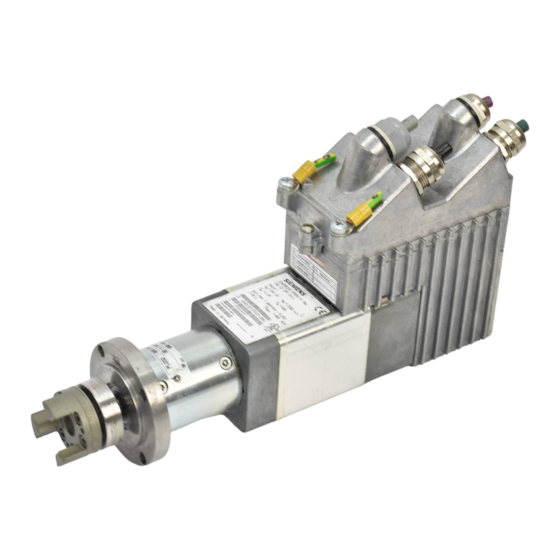
SIMODRIVE POSMO A – 300 W
Montageanleitung Verlängerungssatz "getrennte Variante"
Assembly Instructions extension set "Separate variant"
nicht maßstäblich
not to scale
SW 3
POSMO A – 300 W
Vor dem Demontieren
!
der Antriebseinheit
muss der Positionier-
Warnung
motor spannungsfrei
geschaltet werden.
Warning
Before disassemble
the drive unit, the po-
sitioning motor must
be in a no-voltage
condition.
Was wird zum Tausch der Antriebseinheit benötigt?
1. Werkzeug
– Drehmomentschlüssel (Innensechskantschlüssel SW 3)
2. Verlängerungssatz "getrennte Variante"
Montageablauf
Spannungsfrei schalten, gegen Wiedereinschalten sichern.
1
Die vier Befestigungsschrauben der Antriebseinheit lösen und entfernen
(nicht wiederverwenden!).
– Innensechskantschlüssel SW 3
2
Antriebseinheit abziehen.
1)
3
Optional: Leitung an Steckerstift (Stecker A, B) verdrahten
4
Verlängerungsatz "getrennte Variante" an Motor und Antriebseinheit stecken.
5
Verlängerungssatz mit jeweils 4 Befestigungsschrauben aus den Beipack
an Motor und der Antriebseinheit anschrauben.
– Drehmomentschlüssel (Innensechskant SW 3)
– Schrauben wechselnd diagonal anziehen
– Drehmoment: 1.8 Nm
Potentialausgleichsleiter und Schutzverbindungsleiter (PE) anbringen.
Positioniermotor testen.
Siemens AG 2006 All Rights Reserved
GWE–Nr. / GWE No.: A5E00397126A_af
Ausgabe 12.06
Edition 12.06
4 Schrauben lösen und entfernen
1
Loosen and remove four screws
4 Schrauben aus Beipack
Four screws from the accessories pack
Antriebseinheit
Drive unit
2
4 Schrauben aus Beipack
Four screws from the accessories pack
A
4
Motor
Motor
What do you need when replacing the drive unit?
1. Tool
– Torque wrench (hexagon-socket wrench Size 3)
2. Extension set "Separate variant"
Installation sequence
Disconnect from the supply, safeguard against restart.
1
Loosen and remove the four mounting screws of the drive unit
(do not reuse!).
– Hexagon-socket wrench SW 3
2
Remove drive unit.
1)
3
Optional: Cable to connector pin (connector A, B) connect-up
4
Plug in extension set "Separate variant" in motor and drive unit.
Fix the extension set to the motor and the drive unit with four
5
mounting screws each from the accessories pack.
– Torque wrench (hexagon-socket wrench Size 3)
– Tighten-up the screws alternating diagonally
– Torque: 1.8 Nm
Attach the potential bonding conductor and protective
conductor (PE).
Test the positioning motor.
Hotline
Tel. / Fax: +49 (0)180 / 5050 – 222 / 223
email: adsupport@siemens.com
4
B
1)
9
9
4
14
3
14
4
8
8
3
13
13
3
7
7
2
12
12
2
6
6
1
11
11
1
1)
3
U
U
V
V
W
Stecker B/Connector B
W
Potentialausgleichsleiter und Schutzverbindungsleiter (beidseitig) M5 x 10
Stecker A/Connector A
potential bonding conductor and protective conductor (PE) (through–hole) M5x10
Farbe Leitung/Cable color
grün-rot/green-red
grün/green
weiß-schwarz/white-black
gelb/yellow
braun-gelb/ brown-yellow
braun/brown
grau/gray
schwarz/black
orange/orange
braun-blau/brown-blue
blau/blue
rot/red
schwarz/black U/L1/C/L+
schwarz/black V/L2
schwarz/black W/L3/D/L–
Hinweis/Note
1)Nur bei beigelegten Steckern/only of include connector
Die Lamellen der Verschraubung müssen mittig auf das Kupferband der Leitung montiert werden./
The lamellae of the cable gland must be connected in the middle of the copper adhesive tape.
Drehmoment der Verschraubung 17 Nm/tightimg torque of the cable gland 17 Nm
Benutzerhandbuch Deutsch
Bestell–Nr. (MLFB): 6SN2197-0AA00-0APV
V: Platzhalter für Ausgabestand
User Manual
English
Order No. (MLFB):
6SN2197-0AA00-0BPV
V: space for edition
Potentialausgleichsleiter und Schutzverbindungsleiter
(Durchgangsbohrung) M5 x 10
Potential bonding conductor and protective conductor (PE)
(through-hole) M5 x 10
Antriebseinheit
Drive unit
Verlängerungssatz "getrennte Variante"
Extension set "Separate variant"
5
5
1)
3
Leitung an Steckerstift (Stecker A, B) verdrahten
Cable to connector-pin (connector A, B) connect-up
Stecker A/Connector A
Stecker B/Connector B
11
1
12
2
13
3
14
4
6
6
7
7
8
8
9
9
1
11
2
12
3
13
4
14
U
U
V
V
W
W
nicht maßstäblich / not to scale
Maße in mm / Dimensions in mm

Verwandte Anleitungen für Siemens SIMODRIVE POSMO A


Inhaltszusammenfassung für Siemens SIMODRIVE POSMO A
- Seite 1 Benutzerhandbuch Deutsch SIMODRIVE POSMO A – 300 W Bestell–Nr. (MLFB): 6SN2197-0AA00-0APV V: Platzhalter für Ausgabestand Montageanleitung Verlängerungssatz “getrennte Variante” Ausgabe 12.06 User Manual English Assembly Instructions extension set “Separate variant” Edition 12.06 Order No. (MLFB): 6SN2197-0AA00-0BPV V: space for edition nicht maßstäblich...
- Seite 2 1. Alle Arbeiten dürfen nur von qualifiziertem Fachpersonal 1. Only trained, qualified technicians may work on the equipment. durchgeführt werden. Vor Beginn jeder Arbeit am SIMO- Before you start working on or with SIMODRIVE POSMO A, Bohrbild DRIVE POSMO A müssen die 5 Sicherheitsregeln beachtet...