Inhaltszusammenfassung für nVent RAYCHEM TCON-CSD/20
Seite 1
TCON-CSD/20 DIGITAL THERMOSTAT-DIGITALER THERMOSTAT-THERMOSTAT NUMÉRIQUE Operating Instructions Betriebsanleitung Notice de mise en service Downloaded from www.Manualslib.com manuals search engine...
Seite 2
Downloaded from www.Manualslib.com manuals search engine...
Seite 3
TCON-CSD/20 DIGITAL THERMOSTAT Operating Instructions Downloaded from www.Manualslib.com manuals search engine...
1� IDENTIFYING THE INSTRUMENT The nameplate with information is affixed to the side of the instrument. The supply voltage connected must correspond to the voltage specified on the nameplate. All necessary settings are described in these Operation Instructions. However, if any difficulties should still arise during start-up, you are asked not to carry out any unauthorized manipulations on the unit.
3� ELECTRICAL CONNECTION 3�1 Installation notes • The choice of cable, the installation, the fusing and the electrical connection must conform to the requirements of VDE 0100 “Regulations on the Installation of Power Circuits with nominal voltages below 1000 V” or the appropriate local regulations.
3�2 Connection diagram Supply voltage The electrical connection must only be carried out by - 230V AC +10/-15% specialist personnel! - 115V AC +10/-15% - 12 - 24V DC +15/-15% / 24V AC +15/-15%, 48 - 63Hz Measurement input Resistance thermometers: - Pt100 / Pt1000 / KTY2X-6 Relay output changeover (floating)
4� COMMISSIONING THE INSTRUMENT 4�1 Displays and controls LC display 3-digit 9-segment display, 6 mm high, and symbols for the temperature unit LED K1 LED K1 lights up when the relay is energized. LED K1 goes out when the relay is de-energized. Keys Programming Increase value...
4�2 Setting the instrument functions (parameter level) Time-out If no key is pressed for 60 seconds, the instrument automatically switches back to process value display, see Overview of operation on the first inside page. The instrument functions and values are set at the parameter level. * Press for 3 seconds and will appear alternately.
Seite 12
Controller Parameter Meaning Value range from...factory-set...to Setpoint SP.L ... 0�0 ... SP.H target value of control action (temperature value, current or voltage). Hysteresis 0.2 ... 1�0 ... 99.9 Low setpoint limit -999 ... –50 ... +999 SP.l SP can be set up to this low limit. High setpoint limit -999 ...
Seite 13
Parameter Meaning Value range from...factory-set...to Switch-on delay after power-on 0 ... 60 min for staggered switch-on of several equipment units. Minimum ON time 0 ... 999 s t.On Minimum OFF time 0 ... 999 s t.OF Here you can set the time for which the equipment unit, for instance, has to remain switched on or off.
Seite 14
Alarms Parameter Meaning Value range from...factory-set...to Low alarm limit -999 ... –200 ... +999 Al.L As soon as the process value falls below this limit, the alarm message Al.Lis displayed, see Chapter 7 “Alarm messages”. High alarm limit -999 ... 500... +999 Al.H As soon as the process value goes above this limit, the alarm message Al.His displayed, see Chapter 7 “Alarm messages”.
Seite 15
Input Parameter Meaning Value range from...factory-set...to Sensor connected in 2-wire circuit Pt100: S.En P.ih Measurement input group 1 on Type: 701050/X1X-1-XX Pt1000: P. it KTY2X-6: Start value for indication range with measurement input voltage or –999 ... 0... +999 S.cL current.
Seite 16
Parameter Meaning Value range from...factory-set...to Lead compensation resistance 0.0 ... 0�0 ... 99.9 in Ω OF.r This value is used for compensating the resistance of the probe lead for resistance sensors and is dependent on the lead length. For best temperature measurement results, the resistance value of the probe lead has to be entered here.
Seite 17
Parameter Meaning Value range from...factory-set...to Filter time constant 0.0 ... 0�8 ... 99.9 s For adapting the digital input filter. At a signal step, 63% of the changes are registered after the filter time constant has elapsed. Values between 0.1 and 0.7 are interpreted as 0.8 (sampling time). If the filter time constant is long: - high damping of interference signals - slow reaction of the process value display to process value changes...
4�3 Allocating user rights (enabling level) The setting at the enabling level defines user rights which determine whether a parameter is shown at the operating level, can be edited or is not shown at all. * Press for 3 seconds and appears.
6� TECHNICAL DATA Meas� input Designation Range Meas� accuracy Recognition of ��� ambient Probe Probe temperature error shortcircuit break Resistance Pt100 EN 60 751 –200 to +600°C 0.1%/ ≤100ppm/°C thermometer Pt1000 EN 60 751 –200 to +600°C 0.1%/ ≤100ppm/°C KTY2X-6 (PTC) 50 to +150 °C 1%/ ≤100ppm/°C Measuring current with Pt100: 0.2 mA, with Pt1000 and KTY2X-6: 0.02 mA.
Seite 21
Ambient conditions Ambient temperature range 0 to +55°C, with side-by-side mounting: 0 to +40°C Storage temperature range –40 to +70°C Climatic conditions ≤ 75% rel. humidity, no condensation Output Relais K1 (changeover contact) 150,000 operations at 10A/250V AC 50Hz resistive load 800,000 operations at 3A/250V AC 50Hz resistive load Supply Supply voltage...
Seite 22
Housing Material Polycarbonate Mounting DIN rail 35mm x 7.5mm to EN 50 022 Operating position Unrestricted Weight Approx. 110g Protection IP20 Flammability class UL 94 V0 Electrical data Data backup EEPROM Connection Screw terminals for wire cross-sections up to 2.5 mm Electromagnetic compatibility EN 61 326 interference emission...
6�1 Setup program The program and the interface with adapter are available as accessories and offer the following advantages: • Simple and convenient parameterization and archiving from a PC • Simple duplicating of parameters on instruments of the same type •...
ALARM MESSAGES The following alarm messages can be shown in the temperature display: Error message Cause Elimination Display overrun • Check sensor and connecting cable for damage The measured value is too or short-circuit large and outside the range. • Check whether the correct sensor has been set or connected Display underrun Chapter 4 “Commissioning the instrument”...
Seite 25
Downloaded from www.Manualslib.com manuals search engine...
Seite 26
TCON-CSD/20 TCON-CSD/20 DIGITALER THERMOSTAT Betriebsanleitung Downloaded from www.Manualslib.com manuals search engine...
FUNKTIONSÜBERSICHT Anzeige wechselt > 3 Sekunden Istwertanzeige Sekunden Timeout oder (Gleichzeitig) Code eingeben vergrößern vergrößern verkleinern verkleinern oder 30 Sekunden Timeout Bedienerebene Parameterebene Freigabeebene Parameter, die in der Freigabe- Hier können werkseitig voreinge- Parameter festlegen, die in der ebene ausgewählt wurden. stellte Parameter verändert Bedienerebene angezeigt werden werden.
1� GERÄTEAUSFÜHRUNG IDENTIFIZIEREN Das Typenschild mit Information ist auf der Seite des Gerätes aufgeklebt. Die angeschlossene Spannungsversorgung muss mit der auf dem Typenschild angegebenen Spannung identisch sein. Alle erforderlichen Einstellungen sind in der vorliegenden Betriebsanleitung beschrieben. Sollten trotzdem bei der Inbetriebnahme Schwierigkeiten auftreten, bitten wir Sie, keine unzulässigen Manipulationen am Gerät vorzunehmen.
3� ELEKTRISCHER ANSCHLUSS 3�1 Installationshinweise • Bei der Wahl des Leitungsmaterials, bei der Installation, bei der Absicherung und beim elektrischen Anschluss des Gerätes sind die Vorschriften der VDE 0100 „Bestimmungen über das Errichten von Starkstromanlagen mit Nennspannungen unter 1000 V“ oder die jeweiligen Landesvorschriften zu beachten. •...
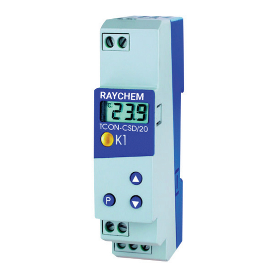
4� GERÄT IN BETRIEB NEHMEN 4.1 Anzeige- und Bedienelemente LC display 6 mm hohe dreistellige Neunsegmentanzeige und Symbole für Temperatureinheit LED K1 LED K1 leuchtet, wenn das Relais angezogen ist.LED K1 erlischt, wenn das Relais abfällt. Tasten Programming Wert vergrößern Bedienstatus in Freigabeebene wählen Wert verkleinern Bedienstatus in Freigabeebene wählen...
4�2 Gerätefunktionen einstellen (Parameterebene) Timeout Wird 60 Sekunden lang keine Taste bedient, schaltet das Gerät automatisch in die Istwertanzeige zurück, siehe Funktionsübersicht auf der ersten Innenseite. In der Parameterebene werden Gerätefunktionen und Werte eingestellt. 3 Sekunden lang drücken und es erscheint abwechselnd * Code 72 für den Zugang zur Parameterebene mit den Tasten einstellen.
Seite 35
Regler Parameter Bedeutung Wertebereich von...werkseitig...bis Sollwert SP.L ... 0�0 ... SP.H Auf diesen Wert wird geregelt (Temperaturwert, Strom oder Spannung). Hysterese 0.2 ... 1�0 ... 99.9 Kühlen Heizen T/°C T/°C SP = 70 °C 69 °C SP = 8 °C Relais K1 Relais K1 angezogen...
Seite 36
Parameter Bedeutung Wertebereich von...werkseitig...bis Einschaltverzögerungszeit nach Netz-Ein 0 ... 60 min Zum zeitversetzten Einschalten mehrerer Aggregate einer Anlage.. Minimale Einschaltdauer 0 ... 999 s t.On Minimale Ausschaltdauer 0 ... 999 s t.OF Hier kann eingestellt werden, wie lange z. B. das Aggregat mindestens einbzw.
Seite 37
Alarme Parameter Bedeutung Wertebereich von...werkseitig...bis Unterer Alarmgrenzwert -999 ... –200 ... +999 Al.L Sobald der Istwert diese Grenze unterschreitet, wird die Alarmmeldung in der Anzeige ausgegeben, siehe Kapitel 7 „Alarmmeldungen“. Al.L Oberer Alarmgrenzwert -999 ... 500... +999 Al.H Sobald der Istwert diese Grenze überschreitet, wird die Alarmmeldung in der Anzeige ausgegeben, siehe Kapitel 7 „Alarmmeldungen“.
Seite 38
Eingang Parameter Bedeutung Wertebereich von...werkseitig...bis Angeschlossener Messwertgeber in Zweileiterschaltung Pt100: S.En P.ih Messeingangsgruppe 1 bei Typ: 701050/X1X-1-XX Pt1000: P. it KTY2X-6: oder Anfangswert für Anzeigebereich bei Messeingang Spannung oder Strom –999 ... 0... +999 S.cL Beispiel: Eingangssignal (z.B. 4 ... 20mA) soll von -10...50 auf der Anzeige abgebildet werden.
Seite 39
Parameter Bedeutung Wertebereich von...werkseitig...bis Leitungsabgleichwiderstand 0,0 ... 0,0 ... 99,9 in Ω OF.r Dieser Wert dient zur Kompensation des Widerstands der Fühlerleitung bei Widerstands-Messwertgebern und ist abhängig von der Leitungslänge. Für eine bestmögliche Temperaturmessung muss hier der ohmsche Widerstand der Fühlerleitung eingegeben werden. Wenn der Gesamtwiderstand am Messeingang ...
Seite 40
Parameter Bedeutung Wertebereich von...werkseitig...bis Filterzeitkonstante 0,1 ... 0,8 ... 99,9 s Zur Anpassung des digitalen Eingangsfilters. Bei einem Signalsprung werden nach der Filterzeitkonstante 63% der Änderungen erfasst. Werte zwischen 0,1 und 0,7 werden als 0,8 interpretiert (Abtastzeit). Wenn die Filterzeitkonstante groß ist: - hohe Dämpfung von Störsignalen - langsame Reaktion der Istwertanzeige auf Istwertänderungen >...
4�3 Bedienrechte vergeben (Freigabeebene) Die Einstellung in der Freigabeebene legt Bedienrechte fest, die darüber entscheiden, ob ein Parameter in der Bedienebene erscheint, editiert werden kann oder gar nicht erscheint. 3 Sekunden lang drücken und erscheint. * Code 82 für den Zugang zur Freigabeebene mit den Tasten einstellen.
5� BEDIENEN Sollwert und weitere Parameter ändern Softwareversion anzeigen Istwertanzeige (gleichzeitig) (Beispiel) Sollwert Weitere Parameter anzeigen (je nach eingestelltem Bedienrecht in der Freigabeebene) nVent.com | 42 Downloaded from www.Manualslib.com manuals search engine...
6� TECHNISCHE DATEN Messeingang Bezeichnung Messbereich Messgenauigkeit Erkennung von ��� Umgebungstemper- Fühlerkur- Fühlerbruch atureinfluss zschluss Widerstands- Pt 100 DIN EN 60751 –200 … +600°C 0,1%/ ≤100ppm/K thermometer Pt 1000 DIN EN 60751 –200 … +600°C 0,1%/ ≤ 100ppm/K KTY2X-6 (PTC) –50 ...
Seite 44
Umwelteinflüsse Umgebungstemperaturbereich 0 ... +55°C, bei Dicht-an-dicht-Montage: 0 ... +40°C Lagertemperaturbereich –40 ... +70°C Klimafestigkeit ≤ 75% rel. Feuchte ohne Betauung Ausgang Relais K1 (Wechselkontakt) 150.000 Schaltungen bei AC 10A/250V 50Hz ohmscher Last 800.000 Schaltungen bei AC 3A/250V 50Hz ohmscher Last Spannungsversorgung Spannungsversorgung AC 230V +10/-15%, 48 ...
Seite 45
Gehäuse Material Polycarbonat Montage Hutschiene 35mm x 7,5mm nach EN 50022 Einbaulage beliebig Gewicht ca. 110g Schutzart IP20 Brennbarkeitsklasse UL 94 V0 Elektrische Daten Datensicherung EEPROM Anschlussart Schraubklemmen für Drahtquerschnitte bis max. 2,5 mm El ektromagnetische Verträglichkeit EN 61326 Störaussendung Klasse B Störfestigkeit Industrieanforderung...
6�1 Setup Programm Das Programm und das Interface mit Adapter ist als Zubehör erhältlich und bietet folgende Möglichkeiten: • Einfache und komfortable Parametrierung und Archivierung über PC • Einfaches Duplizieren der Parameter bei Geräten gleichen Typs • Möglichkeit der Eingabe einer Linearisierungstabelle Hard- und Softwaremindestvoraussetzungen: •...
ALARMMELDUNGEN In der Temperaturanzeige können folgende Alarmmeldungen angezeigt werden: Fehleranzeige Ursache Abhilfe Anzeigeüberlauf • Sensor und Anschlussleitung auf Beschädigung Der Messwert ist zu groß oder Kurzschluss überprüfen und liegt außerhalb des • Überprüfen, ob der richtige Sensor eingestellt Messbereichs. oder angeschlossen ist ...
Seite 48
Downloaded from www.Manualslib.com manuals search engine...
Seite 49
TCON-CSD/20 THERMOSTAT NUMÉRIQUE Notice de mise en service Downloaded from www.Manualslib.com manuals search engine...
APERÇU DES FONCTIONS > 3 secondes L’affichage change Affichage de la température secondes Timeout (simultanément) Saisir le code Incrémenter Incrémenter Décrémenter Décrémenter ou 30 s econdes Timeout Niveau “Utilisateur” Niveau “Paramétrage” Niveau “Déverrouillage” Les paramètres préréglés en usine Paramètres sélectionnés au Définir les paramètres qui peuvent peuvent être modifiés ici.
Seite 51
SOMMAIRE 1 Identification de l’appareil �������������������������������������������������������������������������������������������������������������������������������������52 2 Montage ����������������������������������������������������������������������������������������������������������������������������������������������������������������53 3 Raccordement électrique ��������������������������������������������������������������������������������������������������������������������������������������54 3.1 Instructions à propos de l’installation ..........................54 3.2 Schéma de raccordement ..............................55 4 Mise en service de l’appareil ���������������������������������������������������������������������������������������������������������������������������������56 4.1 Affichage et commande ..............................56 4.2 Réglage des fonctions de l’appareil (Niveau “Paramétrage”) ..................
1. IDENTIFICATION DE L’APPAREIL La plaque d'information est collée sur la partie supérieure de l’appareil. La tension appliquée doit correspondre à celle indiquée sur la plaque signalétique. Tous les réglages et toutes les interventions éventuellement nécessaires sont décrits dans cette notice. Cependant, si vous rencontrez des difficultés lors de la mise en service de cet appareil, ne procédez en aucun cas à...
3� RACCORDEMENT ÉLECTRIQUE 3.1 Instructions à propos de l’installation • Veuillez respecter la réglementation en vigueur aussi bien pour le choix du matériel des lignes, pour l’installation, que pour le raccordement électrique de l’appareil. • Le raccordement électrique ne doit être effectué que par du personnel qualifié. •...
3�2 Schéma de raccordement Tension d’alimentation Le raccordement électrique ne doit être effectué que par - 230V AC +10/-15% du personnel qualifié! - 115V AC +10/-15% - 12 à 24V DC +15/-15% / 24V AC +15/-15%, 48 à 63Hz Entrée de mesure - Pt 100 / Pt1000 / KTY2X-6 Sortie relais Inverseur (contact sec)
4. MISE EN SERVICE DE L’APPAREIL 4�1 Affichage et commande Indicateur Indicateur à 3 chiffres de 6 mm de hauteur avec symboles pour température LED K1 LED K1 s’allume lorsque le relais est excité. LED K1 s’éteint lorsque le relais est désexcité. Touches Programmer Incrémenter la valeur sélectionner l’état...
4.2 Réglage des fonctions de l’appareil (niveau "Paramétrage") Timeout Lorsqu’aucune touche n’est actionnée pendant 60 s, l’appareil réaffiche automatiquement la température, voir "Aperçu des fonctions". Fonctions et valeurs sont réglées au niveau "Paramétrage". * Appuyer sur la touche pendant 3 s et s’affiche en alternance.
Seite 58
Régulateur Paramètre Signification Plage des valeurs de...d’usine...à Consigne SP.L à 0�0 à SP.H Régulera sur cette valeur (valeur de la température, courant ou tension). Hystérésis 0.2 à 1�0 à 99.9 Froid Chaud T/°C T/°C SP = 70 °C 69 °C SP = 8 °C Relais Relais...
Seite 59
Paramètre Signification Plage des valeurs de...d’usine...à Enclenchement retardé après mise sous tension 0 à 60min Pour la mise sous tension différée de plusieurs unités de l’installation. Temps d’activation min. 0 à 999 s t.On Temps de désactivation min� 0 à 999 s t.OF On peut régler à...
Seite 60
Alarms Paramètre Signification Plage des valeurs de...d’usine...à Limite inférieure de la température de l’alarme -999 à -200 à +999 Al.L Dès que la valeur réelle passe sous cette limite pendant le mode chaud ou froid un message d’erreur s’affiche voir chap. 7 „Messages Al.L d’erreur“.
Seite 61
Entrée Paramètre Signification Plage des valeurs de...d’usine...à Capteur raccordé en montage 2 fils Pt100: S.En P.ih Groupe d’entrée de mesure 1 pour type : 701050/X1X-1-XX Pt1000: P.it KTY2X-6: Valeur initiale pour plage d’indication pour entrée courant ou tension –999 à 0 à +999 S.cL Exemple : signal d’entrée (par ex.
Seite 62
Paramètre Signification Plage des valeurs de...d’usine...à Résistance de tarage de ligne 0 à 0,0 à 99,9 en Ω OF.r Cette valeur sert à compenser la résistance de la ligne du capteur et dépend de la longueur de la ligne. Pour mesurer la température du mieux possible, il faut saisir ici la résistance ohmique de la ligne du capteur lorsque celui-ci a court- circuité.
Seite 63
Paramètre Signification Plage des valeurs de...d’usine...à Constante de temps du filtre 0,1 à 0,8 à 99,9 s Pour adapter le filtre d’entrée numérique. En cas de perturbation du signal (parasites,...), 63% des modifications sont enregistrés après la constante du filtre. Les valeurs comprises entre 0,1 et 0,7 sont interprétées comme étant 0,8 (temps de scrutation).
4.3 Attribution du code d’accès (niveau "Déverrouillage") Le réglage au niveau "Déverrouillage" définit les droits d’accès qui déterminent si un paramètre s’affiche ou non au niveau "Utilisateur" et s’il peut être édité. * Maintenir la touche enfoncée pendant 3 secondes et s’affiche.
5� COMMANDE Modifier la consigne et les autres Afficher la version software Affichage de la température paramètres (Simultanément) (Exemple) Température modifiée Afficher les autres paramètres (suivant droit d’accès réglé au niveau “Déverrouillage”) nVent.com | 65 Downloaded from www.Manualslib.com manuals search engine...
6� CARACTÉRISTIQUES TECHNIQUES Entrée Désignation Etendue de mesure Précision Détection de ��� Influence de Court-circuit Rupture de la température de sonde sonde ambiante Sonde à Pt 100 EN 60751 –200 à +600°C 0,1%/ ≤100ppm/K résistance Pt 1000 EN 60751 –200 à +600°C 0,1%/ ≤100ppm/K KTY2X-6 (PTC) –50 à...
Seite 67
Influences de l’environnement Plage de température ambiante 0 à +55°C pour montage côte-à-côte : 0 à +40°C Plage de température de stockage –40 à +70°C Résistance climatique ≤ 75% humidité relative sans condensation Sortie Relais K1 (contact inverseur) 150.000 coupures à 10A/250V AC 50Hz en charge ohmique 800.000 coupures à...
Seite 68
Boîtiere Matériel Polycarbonate Montage Rail symétrique 35mm x 7,5mm suivant EN 50022 Position d’utilisation Au choix Poids Env. 110g Indice de protection IP20 Classe d’inflammabilité UL 94 V0 Caractéristiques électriques Sauvegarde des données EEPROM Type de raccordement Bornes à visser pour section de fil jusqu’à 2,5 mm max.
6�1 Logiciel Setup Le logiciel et l’interface avec adaptateur sont en option et offrent les possibilités suivantes: • Paramétrage et archivage simples et aisés par PC • Duplication simple des paramètres pour appareils de type identique • Possibilité de saisir un tableau de linéarisation Conditions logicielles et matérielles: •...
MESSAGES D’ERREUR Les messages d’erreur suivants restent affichés jusqu’à ce que la cause soit supprimée: Message d’erreur Cause Aide Dépassement sup. de capacité d’affichage • Vérifier que le capteur et le câble de raccord. ne La valeur est trop grande et se situe en soient pas endommagé...
Seite 71
nVent.com | 71 Downloaded from www.Manualslib.com manuals search engine...
Seite 72
North America Denmark Italia Österreich Schweiz / Suisse Tel +1.800.545.6258 Tel +45 70 11 04 00 Tel +39 02 577 61 51 Tel +43 (2236) 860077 Tel 0800 551 308 Fax +1.800.527.5703 salesdk@nvent.com Fax +39 02 577 61 55 28 Fax +43 (2236) 860077-5 Fax 0800 551 309 thermal.info@nvent.com...