Inhaltsverzeichnis
Werbung
Verfügbare Sprachen
Verfügbare Sprachen
Quicklinks
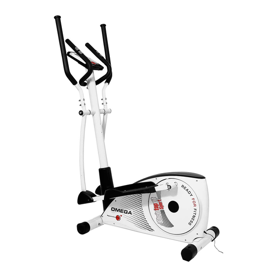
Heimsport-Trainingsgerät
Crosstrainer-Ergometer
Montage- und Bedienungsanleitung
für Bestell-Nr. 1506
Notice de montage et d'utilisation du
No. de commande 1506
Инструкция по монтажу и эксплуатации
Omega
D
GB
Assembly and exercise instructions
for Order No. 1506
F
NL
Montage- en bedieningshandleiding voor
Bestellnummer 1506
RU
№ заказа 1506
1
Werbung
Inhaltsverzeichnis

Verwandte Anleitungen für Christopeit Sport Omega


Inhaltszusammenfassung für Christopeit Sport Omega
- Seite 1 Heimsport-Trainingsgerät Crosstrainer-Ergometer Omega Montage- und Bedienungsanleitung Assembly and exercise instructions für Bestell-Nr. 1506 for Order No. 1506 Notice de montage et d’utilisation du Montage- en bedieningshandleiding voor No. de commande 1506 Bestellnummer 1506 Инструкция по монтажу и эксплуатации № заказа 1506...
-
Seite 2: Wichtige Empfehlungen Und Sicherheitshinweise
Inhaltsübersicht Contents Page 1. Wichtige Empfehlungen und Sicherheitshinweise Seite 2. Einzelteileübersicht Seite 3 - 4 3. Stückliste-Ersatzteilliste-Techn. Daten Seite 5 - 7 Sommaire Page 4. Montageanleitung mit Explosionsdarstellungen Seite 8 - 12 Benutzung des Gerätes, Leistungstabelle 5. Computeranleitung-Störungsbeseitigung Seite 13 - 14 Reinigung, Wartung und Lagerung Inhoudsopgave Pagina 38... - Seite 3 Montageübersicht: Assembly overview: Aperçu de l‘Assemblée: Montage overzicht: Обзор Ассамблея:...
- Seite 5 Stückliste - Ersatzteilliste Grenzwerten wie Zeit, Entfernung, ca. Kalorienverbrauch, Pulsfrequenz und Watt möglich Omega Best.-Nr. 1506 • Überschreitung der Grenzwerte wird angezeigt Technische Daten: • Fitness- Test Anzeige Stand: 01. 07. 2015 • Geeignet bis zu einem Körpergewicht von max. 120 kg Ergometer der Klasse HA / EN 957-1/9 mit hoher Anzeigengenauigkeit Stellmaße: ca.
- Seite 6 Abbildungs- Bezeichnung Abmessung Menge Montiert an ET-Nummer Stück Abbildungs Nr. Rechteckstopfen 36-1506-21-BT Fußschale links 36-1506-08-BT Fußschale rechts 36-1506-09-BT Sterngriffmutter 36-9824-10-BT Unterlegscheibe 6//13 41+80 39-10013-VC Schlossschraube M6x43 39-10410-CR Fußrohr hinten 33-1506-08-WS Fußkappe mit Höhenverstellung 36-1506-06-BT Schraube 39-10187 Schlossschraube M8x90 42+46 39-10445-CR Fußrohr vorne 33-1506-09-WS Fußkappe mit Transportrolleneinheit...
- Seite 7 Abbildungs- Bezeichnung Abmessung Menge Montiert an ET-Nummer Stück Abbildungs Nr. Netzanschlusskabel 65L+89 36-1206-32-BT Motorkabel 9+89 36-1506-30-BT Netzgerät 6Volt=DC/1000mA 36-9103-31-BT Fußhebelhalter links 33-1506-11-WS Fußhebelhalter rechts 33-1506-12-WS Schraube M8x53 39-10056 Wellscheibe 17/22 36-9918-22-BT Kunststofflager 36-1206-18-BT Unterlegscheibe 8//28 39-10159 Innensechskantschlüssel 36-9107-28-BT Multischlüssel 36-9107-27-BT Montage- und Bedienungsanleitung 36-1506-31-BT...
- Seite 8 Montageanleitung Entnehmen Sie alle Einzelteile der Verpackung, legen diese auf den Boden und kontrollieren die Vollzähligkeit anhand der Montageschritte. Das Gerät wurde größtmöglich vormontiert, sodass der Zusammenbau des Gerätes leicht und schnell durchführbar ist. Montagezeit ca. 50Min. Schritt 1: Montage der Fußrohre (42+46) am Grundrahmen (50). 1.
- Seite 9 Schritt 3: Montage der Fußhebel (32), der Verbindungsrohre (19) und der Fußschalen (38). 1. Schieben Sie die Griffachse (7) mittig in die Aufnahme des Stützrohres (10) ein und stecken sie von jeder Seite eine Wellscheibe 17//25 (8) auf. 2. Die Fußschalenaufnahme rechts (32R) mit dem Verbindungsrohr (19R) auf der rechten Seite neben das Gerät bereit legen und die etwas kleinere Wellscheibe 17/22 (99) auf die Pedalarmaufnahme rechts (70) aufschieben.
- Seite 10 Schritt 5: Montage des Haltegriffes (12) am Stützrohr (10). 1. Den Haltegriff (12) zur Aufnahme am Stützrohr (10) führen, und so ausrichten, dass das Lochbild des Haltegriffes (12) und des Stützrohres (10) übereinstimmen. Auf die Schrauben M8x16 (17) jeweils eine Unterlegscheibe 8//16 (3) aufstecken und damit den Haltegriff (12) am Stützrohr (10) festschrauben.
-
Seite 11: Benutzung Des Gerätes
Benutzung des Gerätes Transport des Gerätes: Es befinden sich 2 Transportrollen im vorderen Fuß. Um das Gerät an einen digkeit und des Bremswiderstandes lässt sich die Intensität des Trainings anderen Ort zu stellen oder zu lagern, fassen sie den Haltegriff und kippen Sie steuern. - Seite 12 U/min und Wattleistung von Stufe 1 bis Stufe 24 für Omega Art.-Nr. 1506 Stufe 30 UPM WATT 40 UPM WATT 50 UPM WATT 60 UPM WATT 70 UPM WATT Anmerkung: 1. Die Leistungsanzeige in Watt wurde anhand der Umdrehungszahl der Tretachse pro Minute (UPM) und des Bremsmomentes (Nm) kalibriert.
- Seite 13 Trainingscomputer taste und bestätigen durch Drücken der F-Drehtaste. Alle voreingestellten Werte können mit der F-Taste geändert werden bis das gewünschte Pro- grammprofil blinkt. Mit der F-Drehtaste bestätigen. 3) Wenn das Programm und die anderen Werte eingestellt sind, START/STOP-Taste drücken um das Training zu beginnen. 4) Erneutes Drücken der START/STOP-Taste beendet oder unterbricht das Programm.
-
Seite 14: Reinigung, Wartung Und Lagerung Des Ergometers
PULSMESSUNG: 1. Handpulsmessung: Im linken und rechten Lenkergriffteil ist je eine Metallkontaktplatte, die Sensoren, eingelassen. Bitte darauf achten, dass immer beide Handflächen gleichzeitig mit nor- maler Kraft auf den Sensoren aufliegen. Sobald eine Pulsabnahme erfolgt, blinkt ein Herz neben der Pulsanzeige. (Die Handpulsmessung dient nur zur Orientierung da es durch Bewegung, Reibung, Schweiß... -
Seite 15: Trainingsanleitung
Trainingsanleitung Um spürbare körperliche und gesundheitliche Verbesserungen zu erreichen, Weitere Informationen zum Thema Aufwärmübungen, Dehnungsübungen müssen für die Bestimmung des erforderlichen Trainingsaufwandes die oder allgemeine Gymnastikübungen finden Sie in unserem Downloadbereich folgenden Faktoren beachtet werden: unter www.christopeit-sport.com 1. Intensität: 4. Motivation Die Stufe der körperlichen Belastung beim Training muß den Punkt der Der Schlüssel für ein erfolgreiches Programm ist ein regelmäßiges Training. Sie sollten sich einen festen Zeitpunkt und Platz pro Trainingstag einrichten normalen Belastung überschreiten, ohne dabei den Punkt der Atemlosigkeit und /oder der Erschöpfung zu erreichen. Ein geeigneter Richtwert für ein und sich auch geistig auf das Training vorbereiten. Trainieren Sie nur gut effektives Training kann dabei der Puls sein. Dieser sollte sich während gelaunt und halten Sie sich stets Ihr Ziel vor Augen. Bei kontinuierlichem des Trainings in dem Bereich zwischen 70% und 85% des Maximalpulses Training werden Sie Tag für Tag feststellen, wie Sie sich weiterentwickeln... - Seite 60 Service / Hersteller Bei Reklamationen, notwendigen Ersatzteilbestellungen oder © by Top-Sports Gilles GmbH Reparaturen wenden Sie sich bitte an unsere Service Abteilung. D-42551 Velbert (Germany) Service: Top-Sports Gilles GmbH Tel.: +49 (0)2051/6067-0 Friedrichstrasse 55 info@christopeit-sport.com Fax: +49 (0)2051/6067-44 D - 42551 Velbert http://www.christopeit-sport.com...