Siemens SITRANS Probe LU Kurzanleitung
Vorschau ausblenden
Andere Handbücher für SITRANS Probe LU:
- Schnellstartanleitung (187 Seiten) ,
- Bedienungsanleitung (163 Seiten) ,
- Kurzanleitung (162 Seiten)
Inhaltsverzeichnis
Quicklinks
Level Measurement
Continuous level measurement
Ultrasonic transmitters
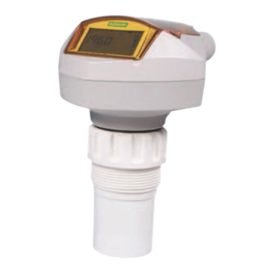
SITRANS Probe LU
■
Overview
4
SITRANS Probe LU is a 2-wire loop powered ultrasonic transmit-
ter for level, volume and flow monitoring of liquids in open chan-
nels, storage vessels, and simple process vessels.
■
Benefits
• Continuous level measurement up to 12 m (40 ft) range
• Easy installation and simple startup
• Programming using infrared Intrinsically Safe handheld
programmer, SIMATIC PDM or HART Communicator
• Communication using HART or PROFIBUS PA
• ETFE or PVDF transducers for chemical compatibility
• Sonic Intelligence signal processing
• Auto False-Echo Suppression for fixed obstruction avoidance
• Level to volume or level to flow conversion
■
Application
The SITRANS Probe LU is ideal for level monitoring in the water
and wastewater industry, chemical storage vessels, and small
bulk hoppers.
The range of SITRANS Probe LU is 6 or 12 m (20 or 40 ft). Using
Sonic Intelligence, Auto False Echo Suppression for fixed ob-
struction avoidance, and accuracy of 0.15 % of range or 6 mm
(0.25 inch), the Probe LU provides unmatched reliability.
The Probe LU offers two communications options: HART or PRO-
FIBUS PA (Profile version 3.0, Class B).
The transducer on the Probe LU is available as ETFE or PVDF to
suit the chemical conditions of your application. As well, for ap-
plications with varying material and process temperatures, the
Probe LU incorporates an internal temperature sensor to com-
pensate for temperature changes.
• Key Applications: chemical storage vessels, filter beds, liquid
storage vessels
4/136
Siemens FI 01 · 2018
© Siemens AG 2018
■
Configuration
Parabolic mounting
Flat mounting and beam angle
Pipe
Rungs
Seams
SITRANS Probe LU mounting
Fill
10°
Beam angle
Kapitel
Inhaltsverzeichnis
Fehlerbehebung

Verwandte Anleitungen für Siemens SITRANS Probe LU


Inhaltszusammenfassung für Siemens SITRANS Probe LU
- Seite 1 Beam angle The range of SITRANS Probe LU is 6 or 12 m (20 or 40 ft). Using Sonic Intelligence, Auto False Echo Suppression for fixed ob- struction avoidance, and accuracy of 0.15 % of range or 6 mm (0.25 inch), the Probe LU provides unmatched reliability.
- Seite 2 Remote: Available via HART or PRO- FIBUS PA • Range 4 ... 20 mA • Accuracy ± 0.02 mA Configuration Using Siemens SIMATIC PDM (PC) or HART handheld communicator or PROFIBUS PA Profile 3, Class B Siemens infrared handheld program- Performance Memory...
- Seite 3 Chapter 7 SITRANS RD500 web, universal remote monitoring 7ML5750-... solution for instrumentation - see Chapter 7 For applicable back up point level switch see point level measurement section. Spare Parts Plastic lid 7ML1830-1KB 4/138 Siemens FI 01 · 2018...
- Seite 4 3" ASME, DN 65 PN 10 and JIS 10K 3B flanges 148.8 (5.86) Bolt hole circle diameter 7ML1830-1BK 190.2 (7.49) Diameter SITRANS Probe LU with optional mounting bracket SITRANS Probe LU optional flange adapter, dimensions in mm (inch) ■ Dimensional drawings Hinged lid 130.1 (5.12) Electronics Mounting thread Transducer 51.1...
- Seite 5 DC terminal shall be supplied from an SELV source in accordance with IEC-1010-1 Annex H. All field wiring must have insulation suitable for rated input voltages. Separate cables and conduit may be required to conform to standard instrumentation wiring practices or electrical codes. SITRANS Probe LU connections 4/140 Siemens FI 01 · 2018...
- Seite 9 Краткая инструкция • декабрь 2004 На русском языке million in one sitrans...
-
Seite 11: Указания По Технике Безопасности
Краткая инструкция по SITRANS Probe LU Данное руководство по эксплуатации содержит краткое изложение основных особенностей и функций SITRANS Probe LU. Для оптимального использования прибора мы рекомендуем ознакомиться с подробной инструкцией. Полное руководство по эксплуатации Вы можете загрузить с нашего веб-сайта: https://pia.khe.siemens.com/index.asp?Nr=11157. Печатную версию Вы можете... -
Seite 12: Технические Данные
, а обработка сигналов – с использованием технологии Sonic Intelligence®. Технические данные Полный список Вы найдете в инструкции по эксплуатации SITRANS Probe LU. Точные сведения о допусках приведены на заводской табличке прибора. Температура окружающей среды / рабочая температура Указание: Температура технологического процесса и значения давления зависят от данных на... -
Seite 13: Напряжение Питания
быть пригодным для использования в условиях эксплуатации. Указание: Установка должна производиться только квалифицированным персоналом в соответствие с местными и законодательными предписаниями. См. приложение А. Для детальной информации см. полную инструкцию по эксплуатации. 7ML19985QR81 SITRANS Probe LU – КРАТКАЯ ИНСТРУКЦИЯ Страница 5... -
Seite 14: Место Монтажа
загрузочного отверстия Инструкции по монтажу Указание: • Идеальным является такой монтаж SITRANS Probe LU, при котором расстояние от нижнего края сенсора до максимального ожидаемого уровня заполнения составляет как минимум 300 мм (1 фут). SITRANS Probe LU предлагается с тремя исполнениями резьбы: 2" NPT, 2" BSP или PF2/G. - Seite 15 усилие от 1,1 до 1,7 Н-м (от 10 до 15 дюйм-фунт). Safety Extra Low Voltage При вводе кабеля через защитную трубу используйте только допущенные резьбовые соединения кабеля соответствующих размеров для применений, требующих герметичности. 7ML19985QR81 SITRANS Probe LU – КРАТКАЯ ИНСТРУКЦИЯ Страница 7...
- Seite 16 Режимы работы и программирования SITRANS Probe LU имеет 2 режима эксплуатации: режим работы (RUN) и режим программирования (PROGRAM). После включения SITRANS Probe LU автоматически запускается в режиме RUN и регистрирует уровень материала. На основном индикаторе отображается уровень материала (в метрах) относительно...
- Seite 17 Режим PROGRAM может быть активирован в любое время для изменения значений параметров и установки условий эксплуатации. • Для программирования на месте используйте ручной программатор Siemens Milltronics. • Для дистанционного программирования используйте персональный компьютер с программным обеспечением SIMATIC PDM или ручной коммуникатор HART.
- Seite 18 Указания: • Во избежание исполнения ошибочной операции не подносите инфракрасные устройства, например, ноутбуки, мобильные телефоны и КПК, к SITRANS Probe LU. • Следующие инструкции относятся к использованию ручного программатора. • Нельзя одновременно использовать ручной программатор и SIMATIC PDM, это может привести к...
- Seite 19 ANTENNE ANTENNE ANTENA (антенна) UNITS P005 EINHEIT UNITES UNIDADES (единицы измерения) EMPTY P006 MESSBER. VIDE VACIO (область измерения) SPAN P007 MESSSPANNE PLAGE RANGO (интервал измерений) LANGUAGE P010 SPRACHE LANGUE IDIOMA (язык) 7ML19985QR81 SITRANS Probe LU – КРАТКАЯ ИНСТРУКЦИЯ Страница 11...
- Seite 20 4 мА 20 мА измерений Интервал Интервал Расстояние (0%) (100%) измерений измерений Воздушная подушка Р006 Р007 Уровень Область Область (100%) (0%) (100%) измерений измерений 20 мА Область 4 мА 20 мА измерений Страница 12 SITRANS Probe LU – КРАТКАЯ ИНСТРУКЦИЯ 7ML19985QR81...
- Seite 21 диапазон (20 футов) или от 0,0000 до Значение 12,000 м (40 футов) по Максимальный диапазон Область умолчанию измерений Нулевая точка может быть установлена на любом уровне, не обязательно на дне резервуара. 7ML19985QR81 SITRANS Probe LU – КРАТКАЯ ИНСТРУКЦИЯ Страница 13...
- Seite 22 Кривая TVT (Time Varying Threshold – порог изменения времени) задает пороговый уровень подавления мешающего отраженного сигнала . Если SITRANS Probe LU показывает неверное высокое значение уровня или если измеряемая величина колеблется между неверным высоким значением уровня и фактическим значением уровня, то в этой области посредством параметров...
-
Seite 23: Техническое Обслуживание
Использование P837 и P838 (продолжение) Указания: • Используйте эту функцию только в том случае, если расстояние от SITRANS Probe LU до материала составляет более двух метров. Для оптимального использования этой функции резервуар должен быть пуст или почти пуст. • По возможности установите P837 и P838 во время ввода в эксплуатацию. - Seite 24 Инструкции по установке во взрывоопасных областях (Европейская директива ATEX 94/9/EC, приложение II, 1/0/6) К SITRANS Probe LU, который является предметом сертификата SIRA 03ATEX2142X, применимы следующие инструкции: 1. Сведения об использовании и монтаже Вы найдете в основной части инструкций. 2. Прибор сертифицирован для эксплуатации как оборудование категории 1G.
- Seite 25 Приложение А: Схемы подключения Взрывобезопасная схема подключения FM Указание: Базовый чертеж 23650516 Вы можете загрузить с нашего веб-сайта: https://pia.khe.siemens.com/index.asp?Nr=11157. 7ML19985QR81 SITRANS Probe LU – КРАТКАЯ ИНСТРУКЦИЯ Страница П-1...
- Seite 26 1) УСТАНОВКА ДОЛЖНА БЫТЬ ВЫПОЛНЕНА В СООТВЕТСТВИЕ С НАЦИОНАЛЬНЫМИ ПРАВИЛАМИ ПО УСТАНОВКЕ ЭЛЕКТРООБОРУДОВАНИЯ. 2) ДЛЯ ПРИМЕНЕНИЙ НА ОТКРЫТОМ ВОЗДУХЕ ИСПОЛЬЗУЙТЕ ДОПУЩЕННЫЕ ВОДОНЕПРОНИЦАЕМЫЕ ТРУБОПРОВОДЫ. 3) ДЛЯ ПОЛУЧЕНИЯ ДЕТАЛЬНОЙ ИНФОРМАЦИИ СМ. РУКОВОДСТВО ПО ЭКСПЛУАТАЦИИ SITRANS Probe LU Страница П-2 SITRANS Probe LU – КРАТКАЯ ИНСТРУКЦИЯ 7ML19985QR81...
- Seite 27 Взрывобезопасная схема подключения CSA Указание: Базовый чертеж 23650517 Вы можете загрузить с нашего веб-сайта: https://pia.khe.siemens.com/index.asp?Nr=11157. 7ML19985QR81 SITRANS Probe LU – КРАТКАЯ ИНСТРУКЦИЯ Страница П-3...
- Seite 28 Заметки Страница П-4 SITRANS Probe LU – КРАТКАЯ ИНСТРУКЦИЯ 7ML19985QR81...
- Seite 29 соответствующих правил техники безопасности. Пожалуйста, примите во внимание следующее: • Пользователь несет ответственность за все изменения и ремонтные работы, проведенные с прибором. • Все новые детали должны быть предоставлены Siemens Milltronics Process Instruments Inc. • Ремонту подлежат только неисправные детали. •...
- Seite 30 Siemens Milltronics Process Instruments Inc. © Siemens Milltronics Process Instruments Inc. 2004 1954Technology Drive, P.O. Box 4225 Право на изменения сохраняется Peterborough, ON, Canada K9J 7B1 Rev. 1.2 Tel: (705) 745-2431 Fax: (705) 741-0466 Email: techpubs.smpi@siemens.com...
- Seite 31 Instruction Manual March 2005 sitrans PROBE LU...
-
Seite 32: Disclaimer Of Liability
The user is responsible for all changes and repairs made to the device by the user or the user’s agent. • All new components are to be provided by Siemens Milltronics Process Instruments Inc. • Restrict repair to faulty components only. -
Seite 33: Inhaltsverzeichnis
SITRANS Probe LU (Ultrasonic) ..................4 Applications ..........................4 Level, volume or flow ......................... 4 SITRANS Probe LU System Implementation ................5 Programming ..........................5 SITRANS Probe LU Approvals and Certificates ..............5 Specifications ........................6 SITRANS Probe LU ..........................6 Power............................. 6 Performance..........................6 Interface ............................7 Programmer (infrared keypad) .................... - Seite 34 Alphabetical Parameter List ......................65 Appendix B ........................68 Programming Chart ..........................68 Appendix C ........................71 HART Communications for the SITRANS Probe LU ..............71 HART Device Description (DD) ....................71 SIMATIC Process Device Manager (PDM): ...............71 HART Communicator 275: .......................72 Supported HART Commands:....................76 Burst mode ..........................
- Seite 35 EU Equivalency .......................... 87 Loop Voltage versus Loop Resistance .................88 IS Safety Barrier Selection .....................88 How to select a passive barrier for SITRANS Probe LU ..........88 PLC Input Modules........................89 Passive Shunt Diode Barriers ....................89 Active barriers (repeating barriers)..................89 Product Nameplate ..........................90...
-
Seite 37: Safety Notes
SITRANS Probe LU. • This manual applies to the SITRANS Probe LU only. This manual will help you set up your SITRANS Probe LU for optimum performance. We always welcome suggestions and comments about manual content, design, and accessibility. Please direct your comments to techpubs.smpi@siemens.com. -
Seite 38: Application Examples
Application Examples The application examples used in this manual illustrate typical installations using SITRANS Probe LU. Because there is often a range of ways to approach an application, other configurations may also apply. In all examples, substitute your own application details. If the examples do not apply to your application, check the applicable parameter reference for the available options. - Seite 39 20 mA above which no PV is Upper Sensor Limit anticipated 100% is most commonly set to 20 mA, and 0% to 4 mA: however, the settings can be reversed. 7ML19985HT01 SITRANS Probe LU – INSTRUCTION MANUAL Page 3...
-
Seite 40: Sitrans Probe Lu (Ultrasonic)
Siemens Milltronics could void the user’s authority to operate the equipment. Note: SITRANS Probe LU is to be used only in the manner outlined in this manual, otherwise protection provided by the equipment may be impaired. SITRANS Probe LU is a loop-powered continuous level monitor, using advanced ultrasonic techniques. -
Seite 41: Sitrans Probe Lu System Implementation
By using the universal linear function of parameter P051, and entering values for Head and Flow in the breakpoint parameters P054 and 055, you can use SITRANS Probe LU to convert head levels into flow rates. SITRANS Probe LU System Implementation SITRANS Probe LU supports the HART communications protocol and SIMATIC PDM software. - Seite 42 Specifications Note: • Siemens Milltronics makes every attempt to ensure the accuracy of these specifications but reserves the right to change them at any time. Environmental • Please check the ambient and operating temperatures under on page Process Approvals (verify against device nameplate) 8, and on page 8;...
-
Seite 43: Power
• display (local) multi-segment alphanumeric liquid crystal with Bar graph (representing level) Programmer (infrared keypad) Siemens Milltronics Infrared IS (Intrinsically Safe) Hand Programmer: for all locations, including hazardous. • approval ATEX II 1 G, EEx ia IIC T4, SIRA 01ATEX2147 •... -
Seite 44: Environmental
, for the specific configuration you are about to use or install. • The use of approved watertight conduit hubs/glands is required for Type 4X / NEMA 4X, Type 6 / NEMA 6, IP67, IP68 (outdoor application). Page 8 SITRANS Probe LU – INSTRUCTION MANUAL 7ML19985HT01... -
Seite 45: Installation
• This product is susceptible to electrostatic shock. Follow proper grounding procedures. • Ideally, mount SITRANS Probe LU so that the face of the transducer is at least 300 mm (1 ft) above the highest anticipated level. Mounting Location Recommendations: •... -
Seite 46: Mounting Instructions
Note: • Ideally, mount SITRANS Probe LU so that the face of the transducer is at least 300 mm (1 ft) above the highest anticipated level. SITRANS Probe LU is available in three thread types: 2" NPT, 2" BSP , or PF2/G. -
Seite 47: Sitrans Probe Lu Dimensions
51. 1 mm (2.01") 54.0 mm (2. 1 3") Flange Adaptor (optional) SITRANS Probe LU can be fitted with the optional 3" (80 mm) flange adaptor for mating to 3" ANSI, DIN 65PN10 and JIS 10K3B flanges. SITRANS Probe LU "A"... -
Seite 48: Wiring
Strip the cable jacket for approximately 70 mm (2.75") from the end of the cable, and thread the wires through the gland Safety Extra Low Voltage If cable is routed through conduit, use only approved suitable-size hubs for waterproof applications. Page 12 SITRANS Probe LU – INSTRUCTION MANUAL 7ML19985HT01... - Seite 49 Tighten the gland to form a good seal. Close the cover and tighten screws: please do not overtighten screws. Recommended torque is 1.1 to 1.7 N-m (10 to 15 in-lb). 7ML19985HT01 SITRANS Probe LU – INSTRUCTION MANUAL Page 13...
-
Seite 50: Operating The Sitrans Probe Lu
SITRANS Probe LU has two modes of operation: RUN and PROGRAM. RUN Mode SITRANS Probe LU automatically starts in RUN mode when power is applied, and detects the material level. The primary reading displays the material level (in meters) referenced from Empty (process empty level). -
Seite 51: Hand Programmer: Function Keys In Run Mode
Activate PROGRAM mode at any time, to change parameter values and set operating conditions. • For local programming, use the Siemens Milltronics hand programmer. • For programming from a distance, use either a PC running SIMATIC PDM, or a HART handheld communicator. -
Seite 52: Low Temperature Effects On Run/Program Modes
RUN mode will operate normally, with the following exceptions: • hand programmer operation is disabled • the LCD displays only limited information: the bar graph and the reliable/ unreliable echo indicator PROGRAM mode: • hand programmer operation is disabled Page 16 SITRANS Probe LU – INSTRUCTION MANUAL 7ML19985HT01... -
Seite 53: Security
Note: For detailed instructions on using the hand programmer, see the next page. For direct access to SITRANS Probe LU, point the hand programmer at the display from a maximum distance of 600 mm (2 ft), and press the keys. -
Seite 54: Accessing A Parameter
Press ENTER to set the value. Parameter Reset to Factory Default Scroll to the parameter or enter its address. Press CLEAR then ENTER . The value returns to the default setting. Page 18 SITRANS Probe LU – INSTRUCTION MANUAL 7ML19985HT01... -
Seite 55: Master Reset (P999)
Enable Auto False-Echo Suppression P837. Return to RUN mode. The language options are English, German, French, or Spanish. The parameter title appears in the language selected, for the first 10 parameters. 7ML19985HT01 SITRANS Probe LU – INSTRUCTION MANUAL Page 19... -
Seite 56: Setup Instructions
To measure how much space remains in the vessel, select Space: • Space returns a reading for the distance between current level and process full level (Span) To measure the distance from the transducer face to the current level, select Distance. Page 20 SITRANS Probe LU – INSTRUCTION MANUAL 7ML19985HT01... -
Seite 57: Set Response Time To Maximum Filling/Emptying Rate (P003: Measurement Response)
29.) Select type of measurement units required (P005: Units) meters centimeters Values millimeters feet inches Blanking Distance Blanking distance is 0.25 m (10"). See on page 82 for more details. 7ML19985HT01 SITRANS Probe LU – INSTRUCTION MANUAL Page 21... - Seite 58 This provides a 0.05 m (2") safety margin, as the minimum detectable distance is 0.25 m (10"). Blanking Distance Blanking distance is 0.25 m (10"). See on page 82 for more details. Page 22 SITRANS Probe LU – INSTRUCTION MANUAL 7ML19985HT01...
- Seite 59 Minimize false reflections (P838: Auto False-Echo Suppression Distance) If SITRANS Probe LU displays an incorrect full level, or if the reading fluctuates between a false high level and a correct level, you can use the TVT (Time Varying Threshold) shaper parameters P838 and P837 together to prevent false-echo detection.
- Seite 60 Press PROGRAM to return to RUN mode. False echoes can be caused by obstructions within the beam path. For more detail, see TVT adjustment parameters, page 57, and TVT curves, page 82. Page 24 SITRANS Probe LU – INSTRUCTION MANUAL 7ML19985HT01...
-
Seite 61: Additional Settings
TVT curve adjustments - Auto False Echo Suppression (P830 to P839) • Software diagnostic tests (P900 and P901) • Adjust measurements (P911 to P924) Parameter Reference For a full list of available parameters, see , starting on page 26. 7ML19985HT01 SITRANS Probe LU – INSTRUCTION MANUAL Page 25... -
Seite 62: Parameter Reference
SITRANS Probe LU is configured through its parameters, and the application determines the parameter values which are entered into the instrument. Please check your value entries carefully before operating SITRANS Probe LU, to ensure optimum performance. Helpful Hints •... -
Seite 63: To Access A Secondary Index And Change A Value
• This lock only applies to the hand programmer: it does not lock access through communications. • A remote master can change configuration if P799 is set to allow this. Secures SITRANS Probe LU from parameter changes via the hand programmer. Unlocked Value (P069) Unlocked: programming permitted... -
Seite 64: Quick Start (P001 To P010)
(P001 = 1) transducer 4 mA face 20 mA 4 mA Span Span Distance Span 100% Space P007 P006 Level Empty Empty 100% 100% Empty 20 mA 20 m A 4 mA Page 28 SITRANS Probe LU – INSTRUCTION MANUAL 7ML19985HT01... - Seite 65 (distance measurement). In this case Span is set to the same value as Empty (P006). • Changing P001 may reset Output Function (P201). P002 Material to be monitored Note: For use only by Siemens Milltronics service personnel. P003 Measurement Response Sets the rate of response to level changes. Failsafe Max.
- Seite 66 See note on next page for more details. Enter the distance between Empty (process empty level) and Span (process full level), in units set in P005. Span can be set at any distance above Empty level. Page 30 SITRANS Probe LU – INSTRUCTION MANUAL 7ML19985HT01...
-
Seite 67: Volume (Or Flow) P050 To P055
(See the table on page 20 for the titles displayed.) Volume (or Flow) P050 to P055 Set SITRANS Probe LU to calculate readings based on reservoir volume instead of level: see P050 Vessel (or Channel) Shape on page 32 for details on displaying flowrate. - Seite 68 P050 Vessel (or Channel) Shape Defines the vessel (or open channel) shape (see chart on next page) and allows SITRANS Probe LU to calculate volume or flow instead of level. The default setting for P050 is 0 (volume calculation not required).
- Seite 69 P051, P052 spherical bottom P051, P052 angled bottom P051, P052 flat end cylinder P051 parabolic end cylinder P051, P052, P053 P051 sphere universal linear P051, P054, P055 level/volume/flow breakpoints 7ML19985HT01 SITRANS Probe LU – INSTRUCTION MANUAL Page 33...
- Seite 70 In P055 you assign a corresponding volume value to each breakpoint. Primary Index P054 Secondary Index Breakpoint number Range 0.0000 to 99999 in units (P005) Values Default 0.000 Related Parameters P055 Volume or Flow Breakpoints Page 34 SITRANS Probe LU – INSTRUCTION MANUAL 7ML19985HT01...
- Seite 71 Volume breakpoint Level value number (P054) (P055) 1200 3200 Note: Illustrated values for P054 and P055 are for example purposes only. For more details on secondary index operation, see page 27. 7ML19985HT01 SITRANS Probe LU – INSTRUCTION MANUAL Page 35...
- Seite 72 0.4 m 113.5 0.3 m 55.3 0.2 m 20.07 head Note: Illustrated values for P054 and P055 are for example purposes only. For more details on secondary index operation, see page 27. Page 36 SITRANS Probe LU – INSTRUCTION MANUAL 7ML19985HT01...
- Seite 73 If you are measuring head and flow, follow the Flow Breakpoints instructions on page 38. Volume breakpoints Each segment defined by the level breakpoints (P054) requires a corresponding volume, so that SITRANS Probe LU can make the level-to-volume calculations. Primary Index P055...
- Seite 74 Flow breakpoints Each segment defined by the head breakpoints (P054) requires a corresponding flow value, so that SITRANS Probe LU can make the head-to-flow calculations. Primary Index P055 Secondary Index Breakpoint number Range 0.0000 to 99999 in units Values Default 0.0000...
-
Seite 75: Lock (P069)
• Default setting for P000 is unlocked. • After a new value has been stored at P069, that value will be recalled after a master reset (P999). • Consult your Siemens Milltronics representative, if you have forgotten the unlocked value. Failsafe (P070 to P073) -
Seite 76: Ma Output (P201 To P215)
For HART, 4 mA and 20 mA represent the upper and lower range limits for the primary variable. Page 40 SITRANS Probe LU – INSTRUCTION MANUAL 7ML19985HT01... - Seite 77 Enter the reading that is to correspond to a 4 mA output. Use percent or units, depending on the setting for P051. P050 Vessel (or Channel) Shape To display flowrate instead of volume, see page 32. 7ML19985HT01 SITRANS Probe LU – INSTRUCTION MANUAL Page 41...
- Seite 78 Prevents the mA output from rising above this maximum level for a measurement value. This does not restrict the Failsafe or manual settings. Range 3.800 to 20.500 (mA) Values Default 20.500 (mA) Page 42 SITRANS Probe LU – INSTRUCTION MANUAL 7ML19985HT01...
-
Seite 79: Installation Records (P300 To P346)
P214 4 mA Output Trim Note: This parameter is for use only by Siemens Milltronics service personnel. Calibrates the 4 mA output. P215 20 mA Output Trim Note: This parameter is for use only by Siemens Milltronics service personnel. Calibrates the 20 mA output. - Seite 80 Key in the index number required, and press ENTER The temperature value associated with the new secondary index appears. Press DISPLAY twice and use the ARROW keys or enter the value for the next desired parameter. Page 44 SITRANS Probe LU – INSTRUCTION MANUAL 7ML19985HT01...
-
Seite 81: Range Calibration (P650 To P654)
Do Offset calibration at any steady level, unless a Sound Velocity calibration is also done. If both calibrations are done, then do Offset at a known high level, and Sound Velocity at a known low level. 7ML19985HT01 SITRANS Probe LU – INSTRUCTION MANUAL Page 45... -
Seite 82: Offset Calibration
The acoustic beam atmosphere temperature is unknown. • The reading accuracy is acceptable only at higher material levels. For best results, calibrate with the level at a known value close to empty. Page 46 SITRANS Probe LU – INSTRUCTION MANUAL 7ML19985HT01... - Seite 83 P654 Sound Velocity at 20 • P660/P661 Temperature setting The units used depend on the setting for P005: • m/s if P005 = 1, 2, or 3 • ft/s if P005 = 4 or 5. 7ML19985HT01 SITRANS Probe LU – INSTRUCTION MANUAL Page 47...
-
Seite 84: Temperature Compensation (P660 To P664)
Use this function when you want to manually override the temperature sensor with a fixed temperature value. • Set P660 to 2. • Enter the fixed temperature value you want to use in place of the sensor temperature. Page 48 SITRANS Probe LU – INSTRUCTION MANUAL 7ML19985HT01... -
Seite 85: Rate (P700 And P701)
These parameters determine how material level changes are reported. P700 Maximum Fill Rate Allows you to further adjust the SITRANS Probe LU response to increases in the actual material level (or an advance to a higher Failsafe Material Level, P071). P700 is automatically updated whenever Measurement Response (P003) is altered. -
Seite 86: Measurement Verification (P709 To P713)
Use this feature to select the measurement verification process. Maximum Verification Values Material Agitator Total Lock P700 Maximum Fill Rate P701 Maximum Empty Rate Related P712 Echo Lock Sampling P713 Echo Lock Window P820 Algorithm Page 50 SITRANS Probe LU – INSTRUCTION MANUAL 7ML19985HT01... - Seite 87 The window then returns to its normal width. When Echo Lock is Off, SITRANS Probe LU responds immediately to a new measurement, as restricted by the Maximum Fill / Empty Rate (P700 / P701). However, measurement reliability is affected.
-
Seite 88: P752 Hart Address
Sets the device address or poll ID on a HART network. Any address other than 0 will cause the output current to be a fixed value, and the current will not indicate the reading. Values Range 0 to 16 Units are those set in P005. Page 52 SITRANS Probe LU – INSTRUCTION MANUAL 7ML19985HT01... -
Seite 89: Communications (P799)
Restricted access – read only except for P799 which is read/write Notes: • P799 controls the access if you are using a HART master. • P000 controls the lock access if you are using the Siemens Milltronics hand programmer. Echo Processing (P800 to P825) The following parameters are for authorized Siemens Milltronics Service personnel or technicians familiar with Siemens Milltronics echo processing techniques. - Seite 90 P801 Range Extension Note: SITRANS Probe LU has an absolute maximum range of 7.2 m (23.6 ft). or 14.4 m (47.24 ft), depending on the model. Allows the material level to drop below Empty (process empty level), without generating an LOE state.
- Seite 91 Displays the absolute strength (in dB above 1 µV rms) of the echo selected as the measurement echo. Values (view only) –20 to 99 Display Press the measurement key to get a new reading that will update echo strength. 7ML19985HT01 SITRANS Probe LU – INSTRUCTION MANUAL Page 55...
-
Seite 92: Algorithm (P820)
Echo Lock Window to be set so that it intersects the Echo Profile at the sharpest rising portion of the Echo Profile. Range 5 to 90% Values Default 50 (%) Page 56 SITRANS Probe LU – INSTRUCTION MANUAL 7ML19985HT01... -
Seite 93: Tvt (Time Varying Threshold) Adjustment Parameters (P830 To P839)
TVT (Time Varying Threshold) Adjustment Parameters (P830 to P839) First SITRANS Probe LU learns the echo profile. Then the learned profile, or part of the learned profile, is used to screen out false echoes. The following parameters are for authorized Siemens Milltronics Service personnel or technicians familiar with Siemens Milltronics echo processing techniques. - Seite 94 • If the vessel contains an agitator, the agitator should be running. If SITRANS Probe LU displays a full level, or if the reading fluctuates between a false high level and a correct level, set P837 to elevate the TVT in this region and to de-sensitize the receiver from any ‘base noise’...
- Seite 95 6. Press 2 and then press ENTER . P837 will revert to 1 (use Learned TVT) automatically after a few seconds. Display after Auto False Echo Suppression TVT curve material (learned) level false echo Distance (meters) 7ML19985HT01 SITRANS Probe LU – INSTRUCTION MANUAL Page 59...
-
Seite 96: Diagnostic Tests (P900 To P924)
P839 TVT Hover Level Defines (in percent) how high the TVT curve is placed above the profile, relative to the largest echo. When SITRANS Probe LU is located in the center of the vessel, lower this parameter to prevent multiple echo detections. -
Seite 97: Measurement
P201 to the previous setting after the test! P912 Temperature Displays the temperature in C (as monitored by the connected transducer). This value is not affected by Temperature Source (P660). Values (view only) Range –40 to 85 ( 7ML19985HT01 SITRANS Probe LU – INSTRUCTION MANUAL Page 61... - Seite 98 Values (view only) Range –99999 to 99999 P922 Space Measurement Displays the distance between the monitored surface and Span / process full level (P007). Values (view only) Range –99999 to 99999 Page 62 SITRANS Probe LU – INSTRUCTION MANUAL 7ML19985HT01...
- Seite 99 The learned TVT curve is not lost. Use this feature after upgrading software: 1. Select P999. 2. Press CLEAR then ENTER to Clear All and initiate reset. 3. Reset complete. (Note: Reset takes several seconds to complete.) 7ML19985HT01 SITRANS Probe LU – INSTRUCTION MANUAL Page 63...
- Seite 100 Notes Page 64 SITRANS Probe LU – INSTRUCTION MANUAL 7ML19985HT01...
-
Seite 101: Appendix A
Echo Marker Trigger Echo Strength Empty (process empty level) Failsafe Level Fail-Safe Material Level Fail-Safe Timer Internal Temperature Language Level (or Head) Breakpoints Lock mA Output Function Maximum mA Limit Minimum mA Limit 7ML19985HT01 SITRANS Probe LU – INSTRUCTION MANUAL Page 65... - Seite 102 Reading Measurement RUN Time Serial Number Software Revision Number Sound Velocity at 20 Sound Velocity Calibration Space Measurement Span (process full level) Temperature Temperature Temperature fixed Temperature source Temperature, transducer maximum Page 66 SITRANS Probe LU – INSTRUCTION MANUAL 7ML19985HT01...
- Seite 103 TVT Hover Level TVT Shaper TVT Shaper Adjust TVT Type Units Unlocked value Velocity Vessel Dimension ‘ A ’ Vessel Dimension ‘L’ Vessel Shape Volume (or Flow) Breakpoints Volume (or Flow) Measurement 7ML19985HT01 SITRANS Probe LU – INSTRUCTION MANUAL Page 67...
-
Seite 104: Appendix B
P210 4 mA Setpoint (low output) P211 20 mA Setpoint (high output) P212 Minimum mA limit P213 Maximum mA limit P214 4 mA Output Trim P215 20 mA Output Trim P300 Temperature, transducer maximum Page 68 SITRANS Probe LU – INSTRUCTION MANUAL 7ML19985HT01... - Seite 105 P807 Noise P820 Algorithm P825 Echo marker trigger P830 TVT Type P831 TVT Shaper P832 TVT Shaper Adjust P837 Auto False-Echo Suppression P838 Auto False-Echo Suppression Distance P839 TVT Hover Level 7ML19985HT01 SITRANS Probe LU – INSTRUCTION MANUAL Page 69...
- Seite 106 P900 Software Revision Number P901 Memory Test P911 mA Output Value P912 Temperature P920 Reading Measurement P921 Material Measurement P922 Space Measurement P923 Distance Measurement P924 Volume (or Flow) Measurement P999 Master Reset Page 70 SITRANS Probe LU – INSTRUCTION MANUAL 7ML19985HT01...
-
Seite 107: Appendix C
Descriptor for the unit in question. HART DD’s are controlled by the HART Communication Foundation. Please contact your local representative concerning the availability of the HART DD for SITRANS Probe LU. Older versions of the library will have to be updated in order to use all the features in the SITRANS Probe LU. -
Seite 108: Hart Communicator 275
6. Manufacturer data 1. Serial No 2. Revision HART information 1. Manufacturer 2. Model 3. HART Dev ID 4. Universal rev 5. Fld dev rev 6. Software rev 7. Hardware rev Page 72 SITRANS Probe LU – INSTRUCTION MANUAL 7ML19985HT01... - Seite 109 1. mA Function cylinder parabol end 2. FS Timer sphere 3. FS default measure universal linear 4. FS Advance 5. FS level val Bk LevVol Gr Bk LevVol 11_11 7ML19985HT01 SITRANS Probe LU – INSTRUCTION MANUAL Page 73...
- Seite 110 3. TVT breakpoint 33 4. TVT breakpoint 34 5. TVT breakpoint 35 6. TVT breakpoint 36 7. TVT breakpoint 37 8. TVT breakpoint 38 9. TVT breakpoint 39 TVT breakpoint 40 Page 74 SITRANS Probe LU – INSTRUCTION MANUAL 7ML19985HT01...
- Seite 111 6. Low Setpoint 7. High Setpoint select Local Display 1. Write protect 2. Lock 3. Write Protect 4. unlock value HART Output 1. Poll addr 2. Num req preams 3. Num resp preams 7ML19985HT01 SITRANS Probe LU – INSTRUCTION MANUAL Page 75...
-
Seite 112: Supported Hart Commands
Supported HART Commands: The SITRANS Probe LU conforms to HART rev. 5 and supports the following: Universal Commands 0, 1, 2, 6, 7, 8, 11, 12, 13, 14, 15, 16, 17, 18, 19, 20, 21, 22 Common Practice Commands 33, 34, 35, 36, 37, 38, 40,41, 42, 44, 45, 46, 48, 50, 51, 53, 54, 59, 110... -
Seite 113: Burst Mode
Burst mode SITRANS Probe LU does not support burst mode. Multidrop Configuration SITRANS Probe LU (HART) does not support multidrop configuration. 7ML19985HT01 SITRANS Probe LU – INSTRUCTION MANUAL Page 77... -
Seite 114: Appendix D: Troubleshooting
The device can be programmed using the hand programmer Verify that the wiring connections are correct. Specifically: If you try to set a SITRANS Probe LU parameter via remote communications, but the parameter remains unchanged: • Some parameters can only be changed when the device is not scanning. Try putting the device in program mode using the operating mode function. -
Seite 115: General Fault Codes
The device was unable to get a measurement for the Check the application and echo failsafe timer period. profile, to determine optimum configuration for the application, to ensure the device can obtain a measurement. 7ML19985HT01 SITRANS Probe LU – INSTRUCTION MANUAL Page 79... - Seite 116 The error will not occur on SITRANS Probe LU, but is included to complete the list and match industry standards. EEPROM can become corrupted due to operating the device outside its operating range (power and temperature) or other damage.
-
Seite 117: Operation Troubleshooting
Please note the following: • The user is responsible for all changes and repairs made to the device. • All new components must be provided by Siemens Milltronics Process Instruments Inc. • Restrict repair to faulty components only. •... -
Seite 118: Appendix E: Technical References
The transducer emits a series of ultrasonic pulses: each pulse is reflected as an echo from the material and sensed by the transducer. The echo is processed by SITRANS Probe LU, using Siemens Milltronics’ proven Sonic Intelligence techniques. Filtering is applied to help discriminate between the true echo from the material, and false echoes from acoustic and electrical noises and agitator blades in motion. - Seite 119 (or when P837 = 0) default TVT true P839 echo Hover Level false echo Distance (meters) Display after Auto False Echo Suppression TVT curve material (learned) level false echo Distance (meters) 7ML19985HT01 SITRANS Probe LU – INSTRUCTION MANUAL Page 83...
-
Seite 120: Open Channel Monitoring (Ocm)
Open Channel Monitoring (OCM) OCM converts a level reading (head) into a flow value using a linear algorithm. SITRANS Probe LU can convert a head level measurement into a flow rate, using an eleven breakpoint head-versus-flow characteristic curve. This chart is usually available from the manufacturer of the v-notch weir, Parshall flume, or other open channel device. -
Seite 121: Failsafe
Failsafe mode without delay. Chemical compatibility The plastic materials used in the construction of SITRANS Probe LU (ETFE, PBT, and PVDF) are resistant to attack from most chemicals. For exposure to specific environments, check with chemical compatibility charts before installing and operating SITRANS Probe LU in your application. -
Seite 122: Appendix F: Hazardous Area Installations
Wiring Details Intrinsically Safe Model (reference drawing 23650516: see page 91) (reference drawing 23650517: see page 93) Under the entity evaluation concept, SITRANS Probe LU has the following characteristics: (input voltage) U = 30 V DC (max.) (input current) I = 120 mA DC (max.) -
Seite 123: Fm/Csa
[ EEx ia ] IIC, its output voltage (U ) not exceeding 30 V and its output current (I ) limited by load resistance (R ); such that I , does not exceed 120 mA. 7ML19985HT01 SITRANS Probe LU – INSTRUCTION MANUAL Page 87... -
Seite 124: Loop Voltage Versus Loop Resistance
How to select a passive barrier for SITRANS Probe LU Make sure that the barrier safety description is suitable for the SITRANS Probe LU Intrinsically Safe (IS) input parameters. Determine the maximum end-to-end resistance of the barrier (Re-e) from the data sheet. -
Seite 125: Plc Input Modules
Notes: • The following list is not complete: there are many safety barriers on the market, which will work with the SITRANS Probe LU. • The barriers listed below have all been tested and are functionally compatible with the SITRANS Probe LU. -
Seite 126: Product Nameplate
Class II, Div 1, Group E, F, G SIRA 03ATEX2142X C i = 3.6 nF, Class III L i = 0 HART WARNING: Possible static hazard, do not rub or clean on site. Page 90 SITRANS Probe LU – INSTRUCTION MANUAL 7ML19985HT01... -
Seite 127: Intrinsically Safe Connection Drawing (Fm)
Intrinsically safe connection drawing (FM) 7ML19985HT01 SITRANS Probe LU – INSTRUCTION MANUAL Page 91... -
Seite 128: Fm Class 1, Div. 2 Connection Drawing
ULTRASONICS 29 / SEPT / 2004 R. CLYSDALE SITRANS Probe LU S. MILLIGAN CLASS I, Div. 2 S. NGUYEN CONNECTION DRAWING PETERBOROUGH FOR INTERNAL USE ONLY 23650583 2365058300 1 : 1 Page 92 SITRANS Probe LU – INSTRUCTION MANUAL 7ML19985HT01... -
Seite 129: Intrinsically Safe Connection Drawing (Csa)
Intrinsically safe connection drawing (CSA) 7ML19985HT01 SITRANS Probe LU – INSTRUCTION MANUAL Page 93... -
Seite 130: Instructions Specific To Hazardous Area Installations
(Reference European ATEX Directive 94/9/EC, Annex II, 1/0/6) The following instructions apply to the SITRANS Probe LU covered by certificate number SIRA 03ATEX2142X: For use and assembly, refer to the main instructions. The equipment is certified for use as Category 1G equipment. - Seite 131 12. Equipment Marking The equipment marking contains at least the information on the product nameplate, shown on page 67. 7ML19985HT01 SITRANS Probe LU – INSTRUCTION MANUAL Page 95...
- Seite 132 Notes Page 96 SITRANS Probe LU – INSTRUCTION MANUAL 7ML19985HT01...
-
Seite 133: Glossary
(decibel): a unit used to measure the amplitude of signals. 7ML19985HT01 SITRANS Probe LU – INSTRUCTION MANUAL Page 97... - Seite 134 Near Blanking: see Blanking nozzle: a length of pipe mounted onto a vessel that supports the flange. parameters: in programming, variables that are given constant values for specific purposes or processes. Page 98 SITRANS Probe LU – INSTRUCTION MANUAL 7ML19985HT01...
- Seite 135 TVT (time varying threshold): a time-varying curve that determines the threshold level above which echoes are determined to be valid. ultrasonic: having a frequency above the human ear’s audibility limit: about 20,000 hertz. 7ML19985HT01 SITRANS Probe LU – INSTRUCTION MANUAL Page 99...
- Seite 136 Notes Page 100 SITRANS Probe LU – INSTRUCTION MANUAL 7ML19985HT01...
-
Seite 137: Index
(RUN) avoiding 51 display echo confidence 15 agitators 51 algorithm hand programmer select for true echo 56 access to SITRANS Probe LU 17 Approvals 8 detailed instructions 18 ARROW keys HART Communications primary/secondary index function 27 detailed information 71... - Seite 138 26 accessing 27 changing value 27 security lock value 39 unlock value 39 setup instructions quick start programming 20 SIMATIC Process Device Manager 71 SIMATIC Process Device Manager (PDM) 71 Page 102 SITRANS Probe LU – INSTRUCTION MANUAL 7ML19985HT01...
- Seite 140 Siemens Milltronics Process Instruments Inc. Siemens Milltronics Process Instruments Inc. 2005 1954Technology Drive, P .O. Box 4225 Subject to change without prior notice Peterborough, ON, Canada K9J 7B1 Rev. 1.4 Tel: (705) 745-2431 Fax: (705) 741-0466 *7ml19985HT01* Email: techpubs.smpi@siemens.com...
- Seite 141 Manuel d'utilisation Juillet 2008 sitrans PROBE LU...
-
Seite 142: Clause De Non-Responsabilité
Peterborough, Ontario, Canada, K9J 7B1 Deutschland e-mail : techpubs.smpi@siemens.com • Pour accéder aux autres manuels de mesure de niveau Siemens Milltronics, voir le site : Level www.siemens.com/processautomation. Sous Process Instrumentation, choisir Measurement puis sélectionner le manuel désiré (les manuels sont listés par famille de produit). - Seite 143 Abréviations et Identifications ....................2 SITRANS Probe LU (ultrasonique) .................4 Applications ..........................4 Niveau, volume ou débit......................4 Mise en application du système SITRANS Probe LU ............5 Programmation ..........................5 Agréments et homologations SITRANS Probe LU ..............5 Caractéristiques Techniques ..................6 SITRANS Probe LU ..........................6 Alimentation ..........................
- Seite 144 Communicateur HART 275 : ....................72 Commandes HART........................76 Mode burst ..........................77 Le SITRANS Probe LU ne supporte pas la communication en mode burst....77 Configuration avec des liaisons multipoints............... 77 Appendice D : Dépistage des défauts .................78 Dépannage - Communication ......................78 Consignes générales : ......................78...
- Seite 145 Tension de la boucle vs. Résistance de la boucle ............88 Sélection d’une barrière sécurité intrinsèque ..............88 Procédure de sélection d’une barrière passive associée au SITRANS Probe LU ... 88 Modules d’entrée API ......................89 Barrières passives à diodes shunt ..................89 Barrières actives (répétitrices)....................
-
Seite 147: Remarques Concernant La Sécurité
Le manuel d’utilisation Notes : • Pour garantir la précision, la fiabilité et l'installation optimale du SITRANS Probe LU il est impératif de respecter les instructions relatives à l'installation et au fonctionnement du système. -
Seite 148: Exemples D'application
Exemples d’application Ce manuel d'utilisation décrit les principaux types d'utilisation du SITRANS Probe LU. Il existe souvent plusieurs approches pour répondre aux besoins de l’application. Les autres configurations peuvent donc s’adapter à ces besoins. Les valeurs fournies dans les exemples doivent toujours être substituées avec les valeurs spécifiques de l’application. - Seite 149 20 mA limite max. applicable à la Upper Sensor Limit valeur mesurée 100% correspond généralement à 20 mA et 0% à 4 mA : ces réglages peuvent être inversés. 7ML19985HT11 SITRANS Probe LU – MANUEL D'UTILISATION Page 3...
-
Seite 150: Sitrans Probe Lu (Ultrasonique)
Le transducteur ultrasonique est doté d’un capteur pour compenser les variations de température. Applications Niveau, volume ou débit Le SITRANS Probe LU est conçu pour mesurer les niveaux de liquides dans une large gamme d'applications : • réservoirs de stockage •... -
Seite 151: Mise En Application Du Système Sitrans Probe Lu
SITRANS Probe LU pour convertir la hauteur de lame en débit instantané. Mise en application du système SITRANS Probe LU Le SITRANS Probe LU est compatible avec le protocole de communication HART et le logiciel SIMATIC PDM. Configuration type API / mA avec HART API actif = 250 Ω... -
Seite 152: Caractéristiques Techniques
Caractéristiques Techniques Note : • Siemens Milltronics vérifie ces informations pour garantir la conformité totale avec les caractéristiques du système, mais se réserve le droit d’apporter des modifications à tout moment. • Vérifier la température ambiante et la température de fonctionnement indiquées sur Caractéristiques environnementales... -
Seite 153: Interface
à cristaux liquides multisegments avec représentation du niveau (bargraph) Programmateur (clavier avec interface infrarouge) Programmateur portatif infrarouge SI (sécurité intrinsèque) Siemens Milltronics : adapté à tout type d'utilisation, y compris en zone dangereuse. • agrément ATEX II 1 G, EEx ia IIC T4, SIRA 01ATEX2147 −20 à... -
Seite 154: Caractéristiques Environnementales
, par rapport à la configuration envisagée. • Utiliser des presse étoupes adaptés pour garantir l'étanchéité dans les applications Type 4X / NEMA 4X, Type 6 / NEMA 6, IP67, IP68 (montage en extérieur). Page 8 SITRANS Probe LU – MANUEL D'UTILISATION 7ML19985HT11... -
Seite 155: Installation
Ce système peut être endommagé par les décharges électrostatiques. Assurer une mise à la terre appropriée. • Pour optimiser le fonctionnement installer le SITRANS Probe LU de telle sorte que la face émettrice du transducteur soit 300 mm (1 ft) au dessus du niveau maximum attendu. -
Seite 156: Instructions Pour Le Montage
émettrice du transducteur soit 300 mm (1 ft) au dessus du niveau maximum attendu. SITRANS Probe LU est disponible avec trois types de filetage : 2" NPT, 2" BSP ou PF2/G. Avant d’insérer le SITRANS Probe LU dans le raccord de montage vérifier que les filetages soient identiques pour éviter de les endommager. -
Seite 157: Dimensions Sitrans Probe Lu
51, 1 mm (2,01") 54,0 mm (2, 1 3") Adaptateur bride (option) Le SITRANS Probe LU peut être équipé avec un adapteur bride 3" (80 mm) optionnel pour brides 3" ANSI, DIN 65PN10 et JIS 10K3B. SITRANS Probe LU "A"... -
Seite 158: Câblage
IEC-1010-1 Annexe H. Isoler tous les câblages en tenant compte des tensions nominales. Connexion du système SITRANS Probe LU Notes : • Utiliser un câble paire blindée / torsadée (jauge AWG 22 - AWG 14/ 0,34 mm à... - Seite 159 1,1 à 1,7 N-m (10 à 15 in-lb). Pour plus de détails sur les installations en sécurité intrinsèque se reporter à Note : Annexe F : Installations en zone dangereuse, page 86. 7ML19985HT11 SITRANS Probe LU – MANUEL D'UTILISATION Page 13...
-
Seite 160: Fonctionnement Du Sitrans Probe Lu
SITRANS Probe LU fonctionne sous deux modes : RUN et PROGRAM(mation). Mode RUN Le système SITRANS Probe LU commute en mode RUN dès la mise sous tension, pour détecter le niveau de produit. Le lecture principale correspond au niveau de matériau (en mètres), depuis le niveau Vide (niveau process vide). -
Seite 161: Mode Program
3 – Indicateur de programmation 4 – Lecture auxiliaire (affichage des noms des paramètres P001 à P010, lorsqu'une langue a été sélectionnée) Affichage de la valeur d’index pour les paramètres indexés ; p.ex. P054.) 7ML19985HT11 SITRANS Probe LU – MANUEL D'UTILISATION Page 15... -
Seite 162: Effets Des Basses Températures Sur Le Fonctionnement En Mode Run/Program
Le système fonctionne normalement en mode RUN.Quelques exceptions : • programmateur portatif désactivé • l’afficheur à cristaux liquides ; limité au bargraph et à l’indicateur de la fiabilité de l’écho Mode PROGRAM : • programmateur portatif désactivé Page 16 SITRANS Probe LU – MANUEL D'UTILISATION 7ML19985HT11... -
Seite 163: Sécurité
à proximité du système. Mettre le système sous tension. Le système SITRANS Probe LU démarre en mode RUN, détecte et affiche le niveau de matériau à partir du 0% (niveau process vide), en mètres. -
Seite 164: Pour Accéder À Un Paramètre
Actualisation du paramètre à la valeur programmée en usine Accéder au paramètre ou entrer l’adresse correspondante. Appuyer sur CLEAR et ENTER . La valeur programmée en usine est restaurée. Page 18 SITRANS Probe LU – MANUEL D'UTILISATION 7ML19985HT11... -
Seite 165: Remise À Zéro Générale (P999)
Activer la Suppression Automatique des échos parasites, P837. Revenir au mode RUN . Les langues disponibles sont : anglais, allemand, français et espagnol. Le nom des 10 premiers paramètres est affiché dans la langue sélectionnée. 7ML19985HT11 SITRANS Probe LU – MANUEL D'UTILISATION Page 19... -
Seite 166: Instructions Pour La Configuration Du Système
Espace permet d’obtenir une lecture correspondante à la distance entre le niveau courant et le niveau process plein (Etendue de mesure) Pour mesurer la distance entre la face émettrice du transducteur et le niveau actuel, sélectionner Distance. Page 20 SITRANS Probe LU – MANUEL D'UTILISATION 7ML19985HT11... - Seite 167 Sélectionner l’unité de mesure souhaitée (P005 : Unités) mètres centimètres millimètres Valeurs pieds pouces Zone morte La zone morte est 0,25 m (10"). Pour plus de détails se reporter à la page 82. 7ML19985HT11 SITRANS Probe LU – MANUEL D'UTILISATION Page 21...
- Seite 168 émettrice du transducteur. Ce réglage permet une distance de sécurité de 0,05 m (2") ; la distance minimale mesurable étant 0,25 m (10"). Zone morte La zone morte est 0,25 m (10"). Pour plus de détails se reporter à la page 82. Page 22 SITRANS Probe LU – MANUEL D'UTILISATION 7ML19985HT11...
- Seite 169 Réduction des réflexions parasites (P838 : Distance de suppression automatique des échos parasites) Si le niveau détecté par le SITRANS Probe LU est incorrect, ou si la lecture varie entre un niveau haut incorrect et un niveau correct, associer les paramètres TVT (Time Varying Threshold) P838 et P837 pour ne pas détecter les échos...
- Seite 170 L’obstruction du faisceau d’émission peut être à l’origine d’échos parasites. Pour plus de détails se reporter aux paramètres de réglage de la courbe TVT, page 57, et aux Courbes TVT, page 82. Page 24 SITRANS Probe LU – MANUEL D'UTILISATION 7ML19985HT11...
-
Seite 171: Réglages Complémentaires
Tests de diagnostic du logiciel (P900 à P901) • Réglage des mesures (P911 à P924) Description des Pour une liste exhaustive des paramètres disponibles, se reporter à paramètres , page 26. 7ML19985HT11 SITRANS Probe LU – MANUEL D'UTILISATION Page 25... -
Seite 172: Description Des Paramètres
• Les valeurs par défaut (programmées en usine) sont identifiées par * dans les tables de paramétrage (sauf indication contraire). Le système SITRANS Probe LU est configuré avec des paramètres. La valeur programmée pour chaque paramètre est sélectionnée en fonction de l’application. -
Seite 173: Pour Accéder À Un Index Secondaire Et Modifier Une Valeur
• Le réglage du paramètre P799 peut permettre à un système maître distant de modifier la configuration malgré le verrouillage. Empêche l’accès non autorisé au réglage du SITRANS Probe LU avec le programmateur. Verrouillage Verrouillage désactivé : programmation autorisée désactivé... -
Seite 174: Mise En Service Simplifiée (P001 À P010)
(P001 = 1) face 4 mA émettrice 20 mA 4 mA Plage Plage Distance Plage 100% Espace P007 P006 Niveau Vide Vide 100% 100% Vide 20 mA 20 mA 4 mA Page 28 SITRANS Probe LU – MANUEL D'UTILISATION 7ML19985HT11... - Seite 175 • La modification de P001 peut entraîner la remise à zéro de la Fonction sortie mA (P201). P002 Matériau contrôlé Utilisable seulement par le personnel Siemens Milltronics. Note : P003 Temps de réponse de la mesure 1* Liquide ou surface plane Valeurs Surface solide entassée ou orientée loin de la face émettrice...
- Seite 176 Entrer la distance entre le 0% (niveau process vide) et le niveau process plein (Plage de mesure). Utiliser l’unité de mesure définie en P005. La Plage de mesure peut correspondre à un niveau au choix, au dessus du 0%. Page 30 SITRANS Probe LU – MANUEL D'UTILISATION 7ML19985HT11...
-
Seite 177: Volume (Ou Débit) P050 À P055
(Pour plus de détails sur les textes affichés se reporter à la page 20.) Volume (ou Débit) P050 à P055 Programmer le SITRANS Probe LU afin que les mesures soient calculées par rapport au volume (au lieu du niveau). Pour plus de détails sur le débit instantané se reporter à P050 Configuration du réservoir (ou du canal), page 32. - Seite 178 Définit la configuration du réservoir (ou canal ouvert) (cf. tableau, page suivante) et permet au SITRANS Probe LU de calculer le volume ou le débit au lieu du niveau. Le réglage par défaut du paramètre P050 est 0 (calcul de volume non nécessaire).
- Seite 179 P051, P052 fond hémisphérique P051, P052 fond plat incliné P051, P052 extrémités planes P051 extrémités paraboliques P051, P052, P053 P051 sphère universel, linéaire points de rupture niveau/ P051, P054, P055 volume/débit 7ML19985HT11 SITRANS Probe LU – MANUEL D'UTILISATION Page 33...
- Seite 180 à chaque point de rupture. P054 Index Primaire Numéro, point de rupture Index secondaire Portée 0,0000 à 99999 en Unité (P005) Valeurs Valeur par défaut 0.000 Paramètres P055 Points de rupture volume ou débit associés Page 34 SITRANS Probe LU – MANUEL D'UTILISATION 7ML19985HT11...
- Seite 181 (P055) 1200 3200 Les valeurs de P054 et P055 sont fournies à titre d'exemple. Note : Pour plus de détails sur le fonctionnement de l'index secondaire se reporter à la page 7ML19985HT11 SITRANS Probe LU – MANUEL D'UTILISATION Page 35...
- Seite 182 0,2 m 20.07 Les valeurs de P054 et P055 sont fournies à titre d'exemple. Note : Pour plus de détails sur le fonctionnement de l'index secondaire se reporter à la page Page 36 SITRANS Probe LU – MANUEL D'UTILISATION 7ML19985HT11...
- Seite 183 Pour mesurer la hauteur de lame et le débit, se reporter aux instructions correspondantes, page 38. Points de rupture volume Pour permettre au SITRANS Probe LU d'effectuer la conversion niveau/volume, chaque segment défini par les points de rupture niveau (P054) doit être associé à un volume. Index Primaire P055 Numéro, point de rupture...
- Seite 184 Points de rupture débit Pour permettre au SITRANS Probe LU d'effectuer la conversion hauteur de lame/débit, chaque segment défini par les points de rupture hauteur de lame (P054) doit être associé à un débit. P055 Index Primaire Numéro, point de rupture Index secondaire Portée...
-
Seite 185: Verrouillage (P069)
• La programmation d’une nouvelle valeur en P069 entraîne le rappel de cette valeur après une Remise à zéro générale (P999). • Veuillez consulter votre représentant Siemens Milltronics si vous avez oublié la valeur requise pour le déverrouillage. Sécurité-défaut (P070 à P073) P070 Temporisation Sécurité-Défaut... -
Seite 186: Sortie Analogique (P201 À P215)
à un point spécifique de la plage de mesure. Dans le cas de HART, 4 mA et 20 mA représentent les limites supérieures et inférieures applicables à la variable principale. Page 40 SITRANS Probe LU – MANUEL D'UTILISATION 7ML19985HT11... - Seite 187 (suivant le réglage de P051). P050 Configuration du réservoir (ou du canal) Se reporter à , page 32 pour obtenir l'affichage du débit instantané au lieu du volume. 7ML19985HT11 SITRANS Probe LU – MANUEL D'UTILISATION Page 41...
- Seite 188 Empêche l’augmentation du signal de sortie mA au dessus du niveau maximum applicable à une valeur de mesure. Cette fonction n’affecte pas les réglages manuels ou Sécurité-Défaut. Portée 3,800 à 20,500 (mA) Valeur par Valeurs 20.500 (mA) défaut Page 42 SITRANS Probe LU – MANUEL D'UTILISATION 7ML19985HT11...
-
Seite 189: Valeurs D'installation (P300 À P346)
P214 Réglage sortie 4 mA Paramètre utilisable uniquement par le personnel Siemens Milltronics. Note : Permet l’étalonnage de la sortie 4 mA. P215 Réglage sortie 20 mA Paramètre utilisable uniquement par le personnel Siemens Milltronics. Note : Permet l’étalonnage de la sortie 20 mA. - Seite 190 Entrer le numéro d'index requis et appuyer sur ENTER La température associée à l'index secondaire sélectionnée est affichée. Appuyer deux fois sur AFFICHAGE puis utiliser les FLECHES pour accéder aux paramètre souhaité (ou entrer le numéro directement). Page 44 SITRANS Probe LU – MANUEL D'UTILISATION 7ML19985HT11...
-
Seite 191: Etalonnage De La Plage (P650 À P654)
être associée à un étalonnage de la vitesse du son. Si les deux types d’étalonnage sont nécessaires, effectuer l’étalonnage Décalage à un niveau élevé et l’étalonnage Vitesse du son à un niveau bas. 7ML19985HT11 SITRANS Probe LU – MANUEL D'UTILISATION Page 45... - Seite 192 La température du milieu de propagation des émissions acoustiques n'est pas connue. • Seules les mesures de niveau haut permettent d’obtenir la précision nécessaire. Toujours effectuer l'étalonnage lorsque le niveau atteint une valeur connue, proche du Page 46 SITRANS Probe LU – MANUEL D'UTILISATION 7ML19985HT11...
- Seite 193 Le choix de l'unité utilisée est directement lié au réglage du paramètre P005 : • m/s lorsque P005 = 1, 2, ou 3 • ft/s lorsque P005 = 4 ou 5. 7ML19985HT11 SITRANS Probe LU – MANUEL D'UTILISATION Page 47...
-
Seite 194: Compensation De Température (P660 À P664)
Utiliser cette fonction pour contourner le capteur de température manuellement et utiliser une valeur de température fixe. • Dans ce cas, P660 doit = 2. • Entrer la valeur de température fixe utilisée pour substituer la température mesurée par le capteur. Page 48 SITRANS Probe LU – MANUEL D'UTILISATION 7ML19985HT11... -
Seite 195: Débit Process (P700 Et P701)
10.000 P701 Vitesse de vidange max. Règle la réaction du SITRANS Probe LU aux diminutions du niveau de matériau (ou à l’évolution vers un niveau Sécurité-Défaut (P071) moins élevé). Toute modification de P003, Temps de réponse de la mesure, entraîne le réglage automatique de P701. -
Seite 196: Vérification Des Mesures (P709 À P713)
Vérification maximale Valeurs Agitateur Verrouillage total P700 Vitesse de remplissage max. P701 Vitesse de vidange max. P712 Echantillonneur verrouillage de l’écho Voir aussi… P713 Fenêtre de verrouillage de l’écho P820 Algorithme Page 50 SITRANS Probe LU – MANUEL D'UTILISATION 7ML19985HT11... - Seite 197 Lorsque le Verrouillage total est sélectionné, la Fenêtre de verrouillage de l’écho (P713) correspond automatiquement à 0. Le SITRANS Probe LU est conçu pour sélectionner le meilleur écho, basé sur l’algorithme sélectionné (P820). Si l’écho sélectionné se trouve à l’intérieur de la fenêtre, cette dernière est centrée sur l’écho.
-
Seite 198: P752 Adresse Hart
à 0 entraînera le réglage du courant de sortie à une valeur fixe. Le courant ne correspondra pas à la lecture. Valeurs Portée 0 à 16 L’unité de mesure correspond à l’unité programmée en P005. Page 52 SITRANS Probe LU – MANUEL D'UTILISATION 7ML19985HT11... -
Seite 199: Communication (P799)
Elaboration de l'écho (P800 à P825) Les paramètres décrits dans les pages suivantes sont réservés à nos experts techniques ou au personnel formé qui maîtrise les techniques d’élaboration de l’écho Siemens Milltronics. Il est préférable de visualiser le profil écho avant de modifier ces paramètres. - Seite 200 P801 Extension de la plage SITRANS Probe LU offre une étendue de mesure absolue de 7,2 m (23,6 ft) ou de Note : 14,4 m (47,24 ft) en fonction du modèle. Permet une diminution du niveau en dessous du 0% (niveau process vide), sans déclencher une perte d’écho (LOE).
- Seite 201 Permet de visualiser la taille (en dB au dessus de 1 µV rms) de l’écho sélectionné (mesure). Valeurs –20 à 99 Affichage (visualisation uniquement) Appuyer sur la touche de mesure pour obtenir une nouvelle mesure et actualiser la taille de l’écho. 7ML19985HT11 SITRANS Probe LU – MANUEL D'UTILISATION Page 55...
-
Seite 202: Algorithme (P820)
Fenêtre de verrouillage de l'écho et du Profil écho, au point le plus net du Profil écho. Portée 5 à 90% Valeur Valeurs 50 (%) défaut Page 56 SITRANS Probe LU – MANUEL D'UTILISATION 7ML19985HT11... -
Seite 203: Paramètres De Réglage Avancé Du Tvt (P830 À P839)
Paramètres de réglage avancé du TVT (P830 à P839) Le SITRANS Probe LU obtient le profil écho. Le profil obtenu, ou une partie de ce dernier est utilisé(e) pour éliminer les échos parasites. Les paramètres décrits dans les pages suivantes sont réservés à nos experts techniques ou au personnel formé... - Seite 204 • Si la cuve est pourvue d’un agitateur, s’assurer que ce dernier soit en marche. Si le SITRANS Probe LU indique un niveau plein, ou si la lecture varie entre un niveau haut erroné et un niveau correct, régler P837 pour hausser la courbe TVT dans la zone correspondante.
- Seite 205 6. Appuyer sur 2 et sur ENTER . P837 revient automatiquement à 1 (utiliser courbe TVT obtenue) après quelques secondes. Affichage après la suppression automatique des échos parasites Courbe TVT matière (obtenue) niveau écho parasite Distance (mètres) 7ML19985HT11 SITRANS Probe LU – MANUEL D'UTILISATION Page 59...
-
Seite 206: Vérification (P900 À P924)
Définit la hauteur de la courbe TVT (en pourcentage) par rapport au profil (écho Plus Grand). Si le SITRANS Probe LU est situé au dessus de la partie centrale du réservoir, diminuer la valeur de ce paramètre pour empêcher la détection de plusieurs échos. -
Seite 207: Mesure
Fournit la température en C (relevée par le transducteur connecté au système). Le paramètre P660, Source de température n'influt pas sur cette valeur. Valeurs Portée (visualisation –40 à 85 ( uniquement) 7ML19985HT11 SITRANS Probe LU – MANUEL D'UTILISATION Page 61... - Seite 208 –99999 à 99999 (visualisation uniquement) P922 Mesure de l’espace Distance entre la surface contrôlée et la Plage de mesure / niveau process plein (P007). Valeurs Portée –99999 à 99999 (visualisation uniquement) Page 62 SITRANS Probe LU – MANUEL D'UTILISATION 7ML19985HT11...
- Seite 209 1. Sélectionner P999. 2. Appuyer sur CLEAR et ENTER pour effacer toutes les valeurs et lancer la remise à zéro. 3. Remise à zéro éffectuée. (Note :Cette opération prend quelques secondes.) 7ML19985HT11 SITRANS Probe LU – MANUEL D'UTILISATION Page 63...
- Seite 210 Notes Page 64 SITRANS Probe LU – MANUEL D'UTILISATION 7ML19985HT11...
-
Seite 211: Annexe A
Lecture Lecture - matériau Limite mA maximale Limite mA minimale Matériau Mesure de l’espace Mesure de la distance Mesure de volume (ou de débit) Mise en forme TVT Mises sous tension 7ML19985HT11 SITRANS Probe LU – MANUEL D'UTILISATION Page 65... - Seite 212 Température interne Température max., transducteur Temporisation Sécurité-Défaut Temps de réponse de la mesure Test mémoire Type de TVT Unités Valeur de déverrouillage Valeur de la sortie analogique Verrouillage Verrouillage de l’écho Vitesse Page 66 SITRANS Probe LU – MANUEL D'UTILISATION 7ML19985HT11...
- Seite 213 Paramètre N° de paramètre Page Vitesse de remplissage max. Vitesse de vidange max. Vitesse du son à 20 Volume maximum Zone morte haute 7ML19985HT11 SITRANS Probe LU – MANUEL D'UTILISATION Page 67...
-
Seite 214: Annexe B
P210 Point de consigne 4 mA (sortie basse) P211 Point de consigne 20 mA (sortie haute) P212 Limite mA minimum P213 Limite mA maximum P214 Réglage sortie 4 mA P215 Réglage sortie 20 mA P300 Température max., transducteur Page 68 SITRANS Probe LU – MANUEL D'UTILISATION 7ML19985HT11... - Seite 215 P831 Mise en forme TVT P832 Réglage de la mise en forme TVT P837 Suppression auto. des échos parasites P838 Distance de suppression auto. des échos parasites P839 Niveau d’élévation TVT 7ML19985HT11 SITRANS Probe LU – MANUEL D'UTILISATION Page 69...
- Seite 216 P911 Valeur de la sortie analogique P912 Température P920 Lecture P921 Lecture - Matériau P922 Mesure de l’espace P923 Mesure de la distance P924 Mesure de volume (ou débit) P999 Remise à zéro générale Page 70 SITRANS Probe LU – MANUEL D'UTILISATION 7ML19985HT11...
-
Seite 217: Annexe C
La configuration d’un instrument HART nécessite la Description HART spécifique au système utilisé. Les descriptions HART sont contrôlées par la HART Communication Foundation. Pour plus de détails sur la description HART du système SITRANS Probe LU veuillez contacter votre representant. Assurer la mise à jour des versions précédentes afin d'accéder à... -
Seite 218: Communicateur Hart 275
6. Date fabricant 1. Num. série 2. Révision Infos. HART 1. Fabricant 2. Modèle 3. ID Dev. HART 4. Rév. universelle 5. Rév. dév. Fld 6. Rév. software 7. Rév. hardware Page 72 SITRANS Probe LU – MANUEL D'UTILISATION 7ML19985HT11... - Seite 219 1. Fonction mA extr. paraboliques 2. Tempo S-D sphère 3. Mesure défaut S-D universel, linéaire 4. Avance. S-D 5. Valeur niveau S-D Bk LevVol Gr Bk LevVol 11_11 7ML19985HT11 SITRANS Probe LU – MANUEL D'UTILISATION Page 73...
- Seite 220 5. Pt de rupt. TVT 35 6. Pt de rupt. TVT 36 7. Pt de rupt. TVT 37 8. Pt de rupt. TVT 38 9. Pt de rupt. TVT 39 Pt. de rupt. TVT 40 Page 74 SITRANS Probe LU – MANUEL D'UTILISATION 7ML19985HT11...
- Seite 221 7. Pt de consigne haut sélectionner Affichage local 1. Protection écrit. 2. Verrouillage 3. Protection écrit. 4. Valeur déverr.llage Sortie HART 1. Adresse d'intérrog. 2. Num req preams 3. Num resp preams 7ML19985HT11 SITRANS Probe LU – MANUEL D'UTILISATION Page 75...
-
Seite 222: Commandes Hart
Commandes HART SITRANS Probe LU est conforme à la révision 5 de HART. Le système supporte les commandes suivantes : Commandes universelles 0, 1, 2, 6, 7, 8, 11, 12, 13, 14, 15, 16, 17, 18, 19, 20, 21, 22 Commandes d’utilisation commune... -
Seite 223: Mode Burst
Mode burst Le SITRANS Probe LU ne supporte pas la communication en mode burst. Configuration avec des liaisons multipoints Le SITRANS Probe LU (HART) ne s’adapte pas aux applications avec des liaisons multipoints. 7ML19985HT11 SITRANS Probe LU – MANUEL D'UTILISATION... -
Seite 224: Appendice D : Dépistage Des Défauts
P000 (Verrouillage) correspond à la valeur enregistrée en P069.) • Pour accéder aux paramètres du SITRANS Probe LU en écriture, le paramètre P799, Contrôle de la communication doit = 1. Page 78 SITRANS Probe LU – MANUEL D'UTILISATION... -
Seite 225: Codes D'erreur
Le système n'a pas pu obtenir une mesure pendant la Vérifier l'application et le profil écho temporisation Sécurité-Défaut. pour définir la configuration optimale requise pour l'application et permettre au système d'obtenir une mesure. 7ML19985HT11 SITRANS Probe LU – MANUEL D'UTILISATION Page 79... - Seite 226 Sécurité-Défaut et provoque la commutation du système en mode S-D. Cette erreur ne se produira pas sur le SITRANS Probe LU. Elle est indiquée pour compléter la liste et garantir la conformité avec les standards industriels. Le non respect de la plage de fonctionnement et de température applicable peut entraîner l'altération de l'EEPROM ou une autre panne.
-
Seite 227: Dépannage
Sécurité-Défaut , page 39 pour la durée des périodes d''Attente'. Maintenance Le SITRANS Probe LU ne requiert ni maintenance, ni nettoyage. Réparation de l'unité et limité de responsabilité Toute modification ou réparation doit être effectuée par un personnel qualifié. Respecter les consignes de sécurité. Remarques importantes : •... -
Seite 228: Annexe E : Référence Technique
Principe de fonctionnement Le transducteur émet une série d'impulsions ultrasoniques. Chaque impulsion est réfléchie par le matériau (écho) et détectée par le transducteur. Le SITRANS Probe LU élabore le signal avec les techniques éprouvées Sonic Intelligence de Siemens Milltronics. L'écho est amélioré avec les techniques de filtrage. Le système différencie ansi entre le vrai écho du matériau et les faux échos provoqués par les bruits... - Seite 229 échos parasites (ou lorsque P837 = 0) TVT pré-définie vrai P839 écho niveau d’élévation faux écho distance (mètres) Affichage après la suppression automatique des échos parasites courbe TVT niveau de (obtenue) produit faux écho distance (mètres) 7ML19985HT11 SITRANS Probe LU – MANUEL D’UTILISATION Page 83...
-
Seite 230: Mesure De Débit En Canal Ouvert (Ocm)
L'OCM utilise un algorithme linéaire pour convertir la mesure de niveau (hauteur de lame) en débit. SITRANS Probe LU permet de convertir la mesure de hauteur de lame en débit instantané grâce à une courbe hauteur de lame/débit avec onze points de rupture. Ce tableau est généralement fourni par le fabricant du déversoir à... -
Seite 231: Sécurité-Défaut
Sécurité-Défaut. Compatibilité chimique Les plastiques utilisés dans la conception du système SITRANS Probe LU (ETFE, PBT et PVDF) résistent à la plupart des substances chimiques. Se reporter aux tableaux de compatibilité avant toute utilisation du SITRANS Probe LU dans un environnement spécifique. -
Seite 232: Annexe F : Installations En Zone Dangereuse
Version à sécurité intrinsèque (schéma de référence 23650516 : cf. page 91) (schéma de référence 23650517 : cf. page 93) Suivant le concept d’entité, le SITRANS Probe LU a les caractéristiques suivantes: = 30 V cc (max.) (tension d’entrée) U (courant d’entrée) I... -
Seite 233: Fm/Csa
[ EEx ia ] IIC, dotée d'une tension de sortie maximale (U ) de 30 V et d'un courant de sortie (I ) limité par la résistance de charge (R ); afin que I , ne soit pas supérieur à 120 mA. 7ML19985HT11 SITRANS Probe LU – MANUEL D'UTILISATION Page 87... -
Seite 234: Tension De La Boucle Vs. Résistance De La Boucle
SITRANS Probe LU Se reporter à la description de la barrière de sécurité pour vérifier sa conformité avec les paramètres d’entrée sécurité intrinsèque du système SITRANS Probe LU. Se reporter à la fiche technique de la barrière pour définir la résistance maximale entre ses extrémités (Re-e). -
Seite 235: Modules D'entrée Api
Notes : • Cette liste n’est pas exhaustive. Vous pourrez choisir parmi plusieurs types de barrière de sécurité compatibles avec le SITRANS Probe LU. • Les barrières indiquées ci-dessous ont été testées et sont compatibles avec le système SITRANS Probe LU. -
Seite 236: Plaque Signalétique Du Produit
Class II, Div 1, Group E, F, G SIRA 03ATEX2142X C i = 3.6 nF, Class III L i = 0 HART WARNING: Possible static hazard, do not rub or clean on site. Page 90 SITRANS Probe LU – MANUEL D'UTILISATION 7ML19985HT11... -
Seite 237: Schéma De Référence Pour Connexion Si (Fm)
Schéma de référence pour connexion SI (FM) 7ML19985HT11 SITRANS Probe LU – MANUEL D'UTILISATION Page 91... -
Seite 238: Schéma De Référence Pour Connexion Fm Cl. 1, Div. 2
ULTRASONICS 29 / SEPT / 2004 R. CLYSDALE SITRANS Probe LU S. MILLIGAN CLASS I, Div. 2 S. NGUYEN CONNECTION DRAWING PETERBOROUGH FOR INTERNAL USE ONLY 23650583 2365058300 1 : 1 Page 92 SITRANS Probe LU – MANUEL D'UTILISATION 7ML19985HT11... -
Seite 239: Schéma De Référence Pour Connexion Si (Csa)
Schéma de référence pour connexion SI (CSA) 7ML19985HT11 SITRANS Probe LU – MANUEL D'UTILISATION Page 93... -
Seite 240: Instructions Spécifiques Pour L'installation En Zone Dangereuse
Instructions spécifiques pour l’installation en zone dangereuse (réf. Directive européenne ATEX 94/9/CE, Annexe II, 1/0/6) Consignes applicables au système SITRANS Probe LU objet du certificat N° SIRA 03ATEX2142X : Pour les informations concernant l’utilisation et l’assemblage, se reporter aux instructions principales. -
Seite 241: Glossaire
Elaboration de l’écho : méthode utilisée par le système radar pour déterminer les échos. Emission de signal : émission d’une impulsion, ou mesure. Extension de la plage : distance en dessous du zéro pourcent ou du niveau vide dans une cuve. 7ML19985HT11 SITRANS Probe LU – MANUEL D'UTILISATION Page 95... - Seite 242 TVT afin d’éviter la prise en compte des échos parasites. (Se reporter à TVT.) Taille de l’écho : représente la puissance de l’écho sélectionné en dB au dessus de 1 µV rms Page 96 SITRANS Probe LU – MANUEL D'UTILISATION 7ML19985HT11...
- Seite 243 Ultrasonique : ayant une fréquence supérieure au seuil d'audition de l'oreille humaine, soit environ 20,000 hertz. Zone morte : distance devant la face émettrice du transducteur, où il est impossible de mesurer. Zone morte haute : se reporter à Zone morte 7ML19985HT11 SITRANS Probe LU – MANUEL D'UTILISATION Page 97...
- Seite 244 Notes Page 98 SITRANS Probe LU – MANUEL D'UTILISATION 7ML19985HT11...
-
Seite 245: Index
18 définir le seuil 54 Paramètre 'bruit' 56 FLECHES Paramètres Sécurité-Défaut 39 fonction index primaire/secondaire 27 paramètres volume 31 fonctionnement PDM 71 modes de mesure 28 points de rupture 7ML19985HT11 SITRANS Probe LU – MANUEL D’UTILISATION Page 99... - Seite 246 82 boucle 88 programmateur portatif Tension de la boucle vs. Résistance de la accès au SITRANS Probe LU 17 boucle 88 instructions détaillées 18 touches de fonction (RUN) programmation pour la mise en service affichage de la fiabilité...
- Seite 247 Siemens Milltronics Process Instruments Inc. Siemens Milltronics Process Instruments Inc. 2008 1954Technology Drive, P .O. Box 4225 Subject to change without prior notice Peterborough, ON, Canada K9J 7B1 Rev. 1.4 Tel: (705) 745-2431 Fax: (705) 741-0466 *7ml19985HT11* Email: techpubs.smpi@siemens.com...
- Seite 248 Quick Start Manual November 2005 sitrans PROBE LU (HART)
- Seite 249 Serial No: GYZ / S1034567 Amb.Temp.: – 40°C to 80°C Nom., 30V Max., 4-20 mA Power Rating: 24V Siemens Milltronics Process Instruments Inc., Peterborough Made in Canada Refer to drawing: 23650516 U i = 30 V, I I 1 G I i = 120 mA, Class I, Div 1.
-
Seite 250: All Rights Reserved
SITRANS Probe LU Quick Start Manual This manual outlines the essential features and functions of SITRANS Probe LU. We strongly advise you to acquire the detailed version of the manual so you can use your instrument to its fullest potential. The complete manual is available on our website at: https://pia.khe.siemens.com/index.asp?Nr=11157. -
Seite 251: Ambient/Operating Temperature
Milltronics could void the user’s authority to operate the equipment. Note: SITRANS Probe LU is to be used only in the manner outlined in this manual, otherwise protection provided by the equipment may be impaired. SITRANS Probe LU is a loop-powered continuous level monitor, using advanced ultrasonic techniques. - Seite 252 23650516, or on page 2 of Appendix A, for reference drawing 23650517. FM Class 1, Div. 2 connection drawing on page 3 of Appendix A, for reference drawing 23650583. 7ML19985QR81 SITRANS Probe LU (HART) – QUICK START MANUAL Page EN-3...
-
Seite 253: Mounting Location
The sound path should be: pipe • perpendicular to the monitored surface rungs • clear of rough walls, seams, rungs, or seams other obstructions • clear of the fill path 10° Page EN-4 SITRANS Probe LU (HART) – QUICK START MANUAL 7ML19985QR81... - Seite 254 Ideally, mount SITRANS Probe LU so that the face of the transducer is at least 300 mm (1 ft) above the highest anticipated level. SITRANS Probe LU is available in three thread types: 2" NPT, 2" BSP , or PF2/G. Before inserting SITRANS Probe LU into its mounting connection, ensure that the threads are of the same type to avoid damaging them.
-
Seite 255: Normal Operation
RUN Mode and PROGRAM Mode SITRANS Probe LU has two modes of operation: RUN and PROGRAM. SITRANS Probe LU automatically starts in RUN mode when power is applied, and detects the material level. The primary reading displays the material level (in meters) referenced from Empty (process empty level). - Seite 256 • Activate PROGRAM mode at any time, to change parameter values and set operating conditions. • For local programming, use the Siemens Milltronics hand programmer. • For programming from a distance, use either a PC running SIMATIC PDM, or a HART handheld communicator.
- Seite 257 * Factory setting for P069 is 1954: after a new value is entered and accepted, it becomes the default setting. Activating SITRANS Probe LU Power up the instrument. SITRANS Probe LU starts in RUN mode. Notes: • Keep infrared devices such as laptops, cell phones, and PDA’s, away from SITRANS Probe LU to prevent inadvertent operation.
-
Seite 258: Master Reset (P999)
Key in 999. Press CLEAR then ENTER , to Clear All and initiate reset. The LCD displays C.ALL. Reset complete. (Reset takes several seconds to complete.) 7ML19985QR81 SITRANS Probe LU (HART) – QUICK START MANUAL Page EN-9... - Seite 259 (P001 = 3) transducer face (4 mA) (4 mA) (20 mA) Span Span Span Distance 100% Space P007 P006 Level Empty Empty 100% Empty 100% (20 mA) (4 mA) (20 mA) Page EN-10 SITRANS Probe LU (HART) – QUICK START MANUAL 7ML19985QR81...
- Seite 260 • Always prevent the monitored surface from approaching within 0.3 m (1 ft) of the transducer face. This provides a 0.05 m (2") safety margin, as 0.25 m (10") is the minimum distance detectable. Default setting for Blanking is 0.25 m (10"). 7ML19985QR81 SITRANS Probe LU (HART) – QUICK START MANUAL Page EN-11...
- Seite 261 Using P837 and P838 (continued) Notes: • Use this function only if there is a minimum distance of 2 meters from SITRANS Probe LU to the material. This function works best if the vessel is empty or nearly empty. • Set P837 and P838 during start up, if possible.
- Seite 262 For detailed information, please see the inside back cover. Instructions specific to hazardous area installations (Reference European ATEX Directive 94/9/EC, Annex II, 1/0/6) The following instructions apply to the SITRANS Probe LU covered by certificate number SIRA 03ATEX2142X: 1. For use and assembly, refer to the main instructions.
- Seite 263 12. Equipment Marking: The equipment marking contains at least the information on the product nameplate, shown on the inside front cover of this manual. Page EN-14 SITRANS Probe LU (HART) – QUICK START MANUAL 7ML19985QR81...
- Seite 264 SITRANS Probe LU Kvikstart Manual Denne manual opridser de væsentligste karakteristika og funktioner af SITRANS Probe LU. Vi anbefaler dig kraftigt at anskaffe den detaljerede version af denne manual, så du kan anvende apparatet fuldt ud. Den komplette manual kan fås på vort website: https://pia.khe.siemens.com/index.asp?Nr=11157.
-
Seite 265: Tekniske Data
Transduceren fås i ETFE (ethylen-tetrafluoroethylen) eller PVDF (polyvinylidenfluorid), hvilket gør det muligt at anvende SITRANS Probe LU inden for et stort udvalg af industrier og applikationer, hvor der bruges korrosive kemikalier. Ultralydstransduceren indeholder en temperaturføler for at kompensere for temperaturændringer i applikationen. - Seite 266 CSA Intrinsically Safe connection drawing referencetegning nr. 23650517 på side 2 i Appendiks A. FM Class 1, Div. 2 connection drawing Se referencetegning nr. 23650583 på side 3 i Appendiks A. 7ML19985QR81 SITRANS Probe LU (HART) – KVIKSTART MANUAL Side DA-3...
- Seite 267 • Undgå, at materialpåfyldningen eller andre forhindringer interfererer med lydens vej. Påfyldning Lydens vej bør være: • vinkelret på den målte overflade rør • fri for ru vægge, svejsesøm, stigetrin stigetrin eller andre forhindringer svejsesøm • udenfor påfyldningsområdet 10° Side DA-4 SITRANS Probe LU (HART) – KVIKSTART MANUAL 7ML19985QR81...
-
Seite 268: Elektrisk Installation
SITRANS Probe LU bør ideelt monteres, således at transducerens overflade er mindst 300 mm (1 ft) over det højeste forventede niveau. SITRANS Probe LU fås med tre gevindtyper: 2" NPT, 2" BSP eller PF2/G. Inden SITRANS Probe LU indsættes i montagetilslutningen, skal det kontrolleres, at gevindene er af samme type for at undgå... -
Seite 269: Normal Drift
RUN Mode og PROGRAM Mode SITRANS Probe LU har to driftstilstande: RUN og PROGRAM SITRANS Probe LU starter automatisk i RUN mode, når strømmen sluttes, og måler materialniveauet. Den primære visning viser materialniveauet (i meter) i forhold til Tom (proces tom niveau). - Seite 270 • PROGRAM mode kan aktiveres når som helst for at ændre parameterværdierne og indstille driftsbetingelserne. • Brug Siemens Milltronics håndholdte programmeringsenhed til lokal programmering. • Til fjernprogrammering bruges enten en PC, der kører SIMATIC PDM, eller en HART håndholdt kommunikationsenhed.
- Seite 271 * Fabriksindstillingen for P069 er 1954: når en ny værdi indlæses og accepteres, bliver den standardindstillingen. Aktivering af SITRANS Probe LU Tænd for instrumentet. SITRANS Probe LU starter i RUN mode. Bemærkninger: • Hold infrarøde apparater, såsom bærbare computere, bærbare telefoner og PDA'er væk fra SITRANS Probe LU for at undgå...
-
Seite 272: Master Reset (P999)
åbne parameterfelterne. Indtast 999 Tryk på SLET og derefter på ENTER for at slette alt og starte reset. LCD-skærmen viser C.ALL. Reset afsluttet. (Det tager adskillige sekunder at gennemføre et reset). 7ML19985QR81 SITRANS Probe LU (HART) – KVIKSTART MANUAL Side DA-9... - Seite 273 (P001 = 2) (P001 = 3) Transducer overflade (4 mA) (4 mA) (20 mA) Spændvidde Spændvidde Spændvidde Afstand 100% Tomrum P007 P006 Niveau 100% 100% (20 mA) (4 mA) (20 mA) Side DA-10 SITRANS Probe LU (HART) – KVIKSTART MANUAL 7ML19985QR81...
- Seite 274 • Den målte overflade må aldrig komme nærmere end 0,3 m fra transduceroverfladen. Dette giver en sikkerhedsmargin på 0,05 m, eftersom 0,25 m er den mindste målbare afstand. Standardindstillingen for Slukning er 0,25 m 7ML19985QR81 SITRANS Probe LU (HART) – KVIKSTART MANUAL Side DA-11...
- Seite 275 Ved hjælp af P837 og P838 (fortsat) Bemærkninger: • Brug kun denne funktion, hvis der er en afstand på mindst 2 meter fra SITRANS Probe LU til materialet. Denne funktion virker bedst, hvis beholderen er tom eller næsten tom. • Indstil så vidt muligt P837 og P838 i løbet af opstarten.
-
Seite 276: Vedligeholdelse
Særlige anvisninger vedrørende installation i risikoområder (Reference: det europæiske ATEX Direktiv 94/9/EF, Bilag II, 1/0/6) Følgende anvisninger gælder for SITRANS Probe LU, der er dækket af certifikat nummer SIRA 03ATEX2142X: 1. Hvad angår brug og montage henvises der til de generelle anvisninger. - Seite 277 12. Mærkning af udstyret: Udstyrets mærkning indeholder mindst oplysningerne på produktets navneskilt, der er vist på indersiden af omslaget til denne manual. Side DA-14 SITRANS Probe LU (HART) – KVIKSTART MANUAL 7ML19985QR81...
-
Seite 278: Haftungsausschluss
SITRANS Probe LU Kurzanleitung Diese Betriebsanleitung ist eine Kurzfassung der wesentlichen Merkmale und Funktionen des SITRANS Probe LU. Es ist sehr empfehlenswert, die ausführliche Version der Anleitung zu erwerben, damit Sie Ihr Gerät optimal nutzen können. Die vollständige Betriebsanleitung finden Sie auf unserer Webseite: https://pia.khe.siemens.com/index.asp?Nr=11157. Ein gebundenes Exemplar können Sie von Ihrer örtlichen Siemens Milltronics Vertretung erhalten. -
Seite 279: Technische Daten
Sensor und Prozessanschluss verbunden ist. Als Sensormaterial steht ETFE (Ethylen-Tetrafluorethylen) oder PVDF (Polyvinylidenfluorid) zur Auswahl. Damit ist der SITRANS Probe LU für den Einsatz in zahlreichen Industriebereichen und Applikationen mit korrosiven Chemikalien geeignet. Der Ultraschallsensor besitzt einen integrierten Temperaturfühler, um Temperaturschwankungen in der Applikation auszugleichen. -
Seite 280: Versorgungsspannung
CSA Intrinsically Safe connection drawing Zeichnung Nr. 23650517 unter auf Seite 2, Anhang A. FM Class 1, Div. 2 connection drawing Zeichnung Nr. 23650583 finden Sie unter auf Seite 3, Anhang A. 7ML19985QR81 SITRANS Probe LU (HART) – KURZANLEITUNG Seite DE-3... -
Seite 281: Einbauort
Der Schallkegel muss: • im rechten Winkel zur Oberfläche des Rohr Messstoffs gelangen • Abstand zu störenden Sprossen Einbauten, Sch- weißnähten oder Leit- ersprossen halten Schweiß- • Abstand zur Befüllung nähte 10° halten Seite DE-4 SITRANS Probe LU (HART) – KURZANLEITUNG 7ML19985QR81... -
Seite 282: Anschluss Des Sitrans Probe Lu
Mindestabstand von 300 mm (1 ft.) zwischen der Sensorunterkante und dem maximal zu erwartenden Füllstand gewährleistet ist. SITRANS Probe LU ist in drei Gewindeausführungen erhältlich: 2" NPT, 2" BSP oder PF2/G. Bevor Sie den SITRANS Probe LU einschrauben, überprüfen Sie, dass es sich um denselben Gewindetyp handelt, um eine Beschädigung zu vermeiden. -
Seite 283: Run Modus Und Programmier-Modus
RUN Modus und PROGRAMMIER-Modus Der SITRANS Probe LU besitzt 2 Betriebsarten: RUN und PROGRAMMIERUNG. Sobald das Gerät eingeschaltet ist, startet der SITRANS Probe LU automatisch im RUN Modus und erfasst den Materialfüllstand. Auf der Hauptanzeige erscheint der Materialfüllstand (in Metern) bezogen auf den Messbereich (Nullpunkt des Prozesses). Dies entspricht der Vorein- stellung der Anzeige. -
Seite 284: Anzeige Im Programmier-Modus
• Stellen Sie die Parameter entsprechend Ihrer Applikation ein. • Die PROGRAMMIERUNG kann jederzeit aktiviert werden, um Parameterwerte zu ändern und Betriebsbedingungen einzustellen. • Für die Programmierung am Gerät verwenden Sie den Siemens Milltronics Handprogrammer. • Für eine Fernprogrammierung verwenden Sie entweder einen PC mit SIMATIC PDM, oder einen HART Hand-Communicator. -
Seite 285: Einfluss Niedriger Temperaturen Auf Die Betriebsarten
* Werkseinstellung für P069 ist 1954: nach Eingabe und Bestätigung eines neuen Wertes wird dieser zur Vorgabe. Start des SITRANS Probe LU Schalten Sie das Gerät ein. Der SITRANS Probe LU startet im RUN Modus. Hinweise: • Halten Sie Infrarotgeräte, wie z. B. Laptops, Mobiltelefone und PDAs, vom SITRANS Probe LU fern, um einen versehentlichen Betrieb zu verhindern. -
Seite 286: Zugriff Auf Einen Parameter
Geben Sie den Wert 999 ein. Taste LÖSCHEN gefolgt von ENTER zum Löschen aller Werte und Start des Resets. Auf der LCD erscheint C.ALL. Reset beendet. (Der Reset dauert einige Sekunden.) 7ML19985QR81 SITRANS Probe LU (HART) – KURZANLEITUNG Seite DE-9... -
Seite 287: Auswahl Der Sprache (P010: Sprache)
(P001 = 3) Sensorsende- fläche (4 mA) (4 mA) (20 mA) Messspanne Messspanne Mess- Abstand 100% spanne Leerraum P007 P006 Füllstand Messbereich Messbereich 100% Mess- 100% (20 mA) (4 mA) bereich (20 mA) Seite DE-10 SITRANS Probe LU (HART) – KURZANLEITUNG 7ML19985QR81... -
Seite 288: Einstellung P003: Reaktionszeit
• Die Materialoberfläche sollte immer in einem Abstand von 0,3 m (1 ft) von der Sensorsendefläche gehalten werden. Dies gewährleistet einen Sicherheitsspielraum von 0,05 m (2”), da der minimal erfassbare Abstand 0,25 m (10“) beträgt. Die voreingestellte Ausblendung beträgt 0,25 m (10"). 7ML19985QR81 SITRANS Probe LU (HART) – KURZANLEITUNG Seite DE-11... - Seite 289 Verwendung von P837 und P838 (Fortsetzung) Hinweise: • Verwenden Sie diese Funktion nur, wenn der Abstand vom SITRANS Probe LU zum Material mindestens 2 Meter beträgt. Um diese Funktion optimal zu nutzen, sollte der Tank leer oder fast leer sein.
-
Seite 290: Wartung
Vorschriften bezüglich Installationen in Ex-gefährdeten Bereichen (Europäische ATEX Richtlinie 94/9/EG, Anhang II, 1/0/6) Folgende Vorschriften finden Anwendung auf den SITRANS Probe LU, der Gegenstand des Zertifikats Nr. SIRA 03ATEX2142X ist: 1. Angaben zu Verwendung und Zusammenbau finden Sie im Hauptteil der Vorschriften. - Seite 291 Chemikalien anhand des Datenblatts des Materials. 12. Gerätekennzeichnung: Die Kennzeichnung des Geräts enthält mindestens die Angaben auf dem Typenschild, das vorne auf der Innenseite des Umschlags dieser Betriebsanleitung abgebildet ist. Seite DE-14 SITRANS Probe LU (HART) – KURZANLEITUNG 7ML19985QR81...
-
Seite 292: Οδηγίες Ασφαλείας
αξιοποιήσετε όλες τις δυνατότητες της συσκευής σας. Το πλήρες εγχειρίδιο διατίθεται στην https://pia.khe.siemens.com/index.asp?Nr=11157 τοποθεσία µας web στο ∆ιαδίκτυο: Το εγχειρίδιο σε έντυπη µορφή διατίθεται από τον τοπικό αντιπρόσωπο της Siemens Milltronics. Ερωτήσεις σχετικά µε τα περιεχόµενα του εγχειριδίου αυτού µπορείτε να απευθύνετε προς... - Seite 293 τη Siemens Milltronics θα µπορούσαν να αναστείλουν την άδεια του χρήστη να χρησιµοποιεί τον εξοπλισµό. Σηµείωση: Το SITRANS Probe LU πρέπει να χρησιµοποιείται µόνο µε τον τρόπο που περιγράφεται στο παρόν εγχειρίδιο, διαφορετικά ενδέχεται να διακυβευτεί η ασφάλεια που παρέχει ο εξοπλισµός.
- Seite 294 διαγράµµατος 23650516, ή “CSA Intrinsically Safe connection drawing” σελίδα 2 του Παραρτήµατος A, για αριθµό διαγράµµατος 23650517. Βλέπε “FM Class 1, Div. 2 connection drawing” σελίδα 3 του Παραρτήµατος A, για αριθµό διαγράµµατος 23650583. 7ML19985QR81 SITRANS Probe LU (HART) – ΠΕΡΙΛΗΠΤΙΚΟ ΕΓΧΕΙΡΙ∆ΙΟ Ο∆ΗΓΙΩΝ Σελίδα EL-3...
-
Seite 295: Εγκατάσταση
πρέπει να είναι: • κατακόρυφη προς την υπό παρακολούθηση σωλήνας επιφάνεια • απαλλαγµένη από ανώµαλα τοιχώµατα, βαθµίδες αρµούς, βαθµίδες ή άλλα εµπόδια αρµοί • µακριά από τη διαδροµή πλήρωσης 10° Σελίδα EL-4 SITRANS Probe LU (HART) – ΠΕΡΙΛΗΠΤΙΚΟ ΕΓΧΕΙΡΙ∆ΙΟ Ο∆ΗΓΙΩΝ 7ML19985QR81... -
Seite 296: Οδηγίες Τοποθέτησης
τέτοιον τρόπο, ώστε η επιφάνεια του µορφοτροπέα να βρίσκεται τουλάχιστον 300 mm (1 ft.) πάνω από την υψηλότερη προβλεπόµενη στάθµη. Το SITRANS Probe LU διατίθεται µε τρεις τύπους σπειρωµάτων: 2" NPT, 2" BSP ή PF2/G. Προτού συνδέσετε το SITRANS Probe LU στη θέση τοποθέτησης, βεβαιωθείτε ότι τα... - Seite 297 Το SITRANS Probe LU έχει 2 τρόπους λειτουργίας: RUN και PROGRAM. Το SITRANS Probe LU ξεκινά αυτόµατα στη λειτουργία RUN µε το που θα τροφοδοτηθεί µε ρεύµα και µετρά τη στάθµη υλικού. Η κύρια ένδειξη απεικονίζει τη στάθµη υλικού (σε µέτρα) µε...
- Seite 298 Κύλιση παραµέτρου προς τα κάτω Το DISPLAY ανοίγει τα πεδία παραµέτρων ENTER (καταχώριση) τιµής που απεικονίζεται Πιέστε και έναν τριψήφιο κωδικό παραµέτρου για να ρυθµιστεί η παράµετρος που θα εµφανίζεται στη βοηθητική οθόνη. 7ML19985QR81 SITRANS Probe LU (HART) – ΠΕΡΙΛΗΠΤΙΚΟ ΕΓΧΕΙΡΙ∆ΙΟ Ο∆ΗΓΙΩΝ Σελίδα EL-7...
- Seite 299 * Προεπιλεγµένη ρύθµιση για την P069 είναι η 1954: µετά την εισαγωγή και αποδοχή νέας τιµής, η τιµή αυτή αποτελεί τη νέα προεπιλεγµένη ρύθµιση. Ενεργοποίηση του SITRANS Probe LU Τροφοδοτήστε το όργανο µε ρεύµα. Το SITRANS Probe LU ξεκινά από τη λειτουργία RUN. Σηµειώσεις: •...
- Seite 300 και µετά ENTER , για µηδενισµό/ απαλοιφή όλων και για να ξεκινήσει η επαναφορά. Η οθόνη LCD εµφανίζει την ένδειξη C.ALL. Η επαναφορά ολοκληρώθηκε. (Η επαναφορά µπορεί να διαρκέσει µερικά δευτερόλεπτα.) 7ML19985QR81 SITRANS Probe LU (HART) – ΠΕΡΙΛΗΠΤΙΚΟ ΕΓΧΕΙΡΙ∆ΙΟ Ο∆ΗΓΙΩΝ Σελίδα EL-9...
- Seite 301 (4 mA) (4 mA) Εύρος (20 mA) Εύρος κλίµακας Εύρος κλίµακας κλίµακας 100% Απόσταση Κενός χώρος P007 P006 Στάθµη Κενό Κενό 100% 100% Κενό (20 mA) (4 mA) (20 mA) Σελίδα EL-10 SITRANS Probe LU (HART) – ΠΕΡΙΛΗΠΤΙΚΟ ΕΓΧΕΙΡΙ∆ΙΟ Ο∆ΗΓΙΩΝ 7ML19985QR81...
- Seite 302 από την επιφάνεια του µορφοτροπέα. Έτσι παρέχεται περιθώριο ασφάλειας 0,05 m (2"), δεδοµένου ότι τα 0,25 m (10") είναι η ελάχιστη µετρήσιµη απόσταση. Η προεπιλεγµένη τιµή για τη “Νεκρή ζώνη” είναι 0,25 m (10") 7ML19985QR81 SITRANS Probe LU (HART) – ΠΕΡΙΛΗΠΤΙΚΟ ΕΓΧΕΙΡΙ∆ΙΟ Ο∆ΗΓΙΩΝ Σελίδα EL-11...
- Seite 303 Σηµειώσεις: • Χρησιµοποιήστε τη λειτουργία αυτή µόνο αν υπάρχει ελάχιστη απόσταση 2 µέτρων από το SITRANS Probe LU µέχρι το υλικό. Η λειτουργία αυτή είναι αποτελεσµατική αν το δοχείο είναι άδειο ή σχεδόν άδειο. • Ρυθµίστε τις P837 και P838 κατά την εκκίνηση, αν είναι δυνατόν.
- Seite 304 σελίδα 10 για απεικόνιση της εξόδου mA σε διαφορετικούς τρόπους λειτουργίας. • Θα χρειαστείτε το πλήρες εγχειρίδιο για να δείτε τον κατάλογο όλων των παραµέτρων. • Σχετικά µε τη διαθεσιµότητα του HART DD για το SITRANS Probe LU, επικοινωνήστε µε τον τοπικό αντιπρόσωπο.
- Seite 305 υλικών ότι παρουσιάζουν αντοχές σε συγκεκριµένες χηµικές ουσίες. 12. Σήµανση εξοπλισµού: Η σήµανση του εξοπλισµού περιλαµβάνει τουλάχιστον τις πληροφορίες στην πινακίδα ονόµατος προϊόντος, η οποία φαίνεται στη µέσα µεριά του εξώφυλλου του παρόντος εγχειριδίου. Σελίδα EL-14 SITRANS Probe LU (HART) – ΠΕΡΙΛΗΠΤΙΚΟ ΕΓΧΕΙΡΙ∆ΙΟ Ο∆ΗΓΙΩΝ 7ML19985QR81...
-
Seite 306: Exención De Responsabilidad
Símbolo utilizado cuando el producto no lleva marcado de seguridad. 7ML19985QR81 SITRANS Probe LU (HART) – GUÍA PARA LA PUESTA EN MARCHA Página ES-1... - Seite 307 éste manual. La realización técnica de estas condiciones es la condición para una utilización sin peligro alguno. SITRANS Probe LU es un sistema 2 hilos diseñado para la medición de nivel continua con técnicas ultrasónicas avanzadas. El sistema combina una electrónica conectada a un transductor y la conexión al proceso.
-
Seite 308: Alimentación Eléctrica
Intrinsically Safe connection drawing página 2, Anexo A, diagrama n° 23650517. FM Class 1, Div. 2 connection drawing Consultar página 3 of Appendix A, for reference drawing 23650583. 7ML19985QR81 SITRANS Probe LU (HART) – GUÍA PARA LA PUESTA EN MARCHA Página ES-3... -
Seite 309: Lugar De Montaje
• perpendicular a la tubo superficie controlada peldaños • lejos de paredes rugosas, soldaduras, soldaduras peldaños y otras obstrucciones 10° • lejos de aberturas de llenado Página ES-4 SITRANS Probe LU (HART) – GUÍA PARA LA PUESTA EN MARCHA 7ML19985QR81... - Seite 310 300 mm (1 ft.) entre la superficie emisora del transductor y el máximo nivel esperado. SITRANS Probe LU está disponible con tres tipos de rosca: 2" NPT, 2" BSP o PF2/G. Se recomienda comprobar, antes de insertar el SITRANS Probe LU, que las roscas son idénticas para evitar dañarlas.
-
Seite 311: Funcionamiento Normal
El sistema SITRANS Probe LU tiene dos modos de funcionamiento: RUN y PROGRAM. Una vez completada la puesta en marcha el SITRANS Probe LU arrancará en modo RUN con el cual se detecta el nivel del producto. La lectura principal corresponde al nivel del material (en metros) desde el nivel proceso vacío. -
Seite 312: Modo De Programación
• La programación local se efectúa con el calibrador de mano Siemens Milltronics. • Programación a distancia: utilizar un PC con SIMATIC PDM, o un comunicador portátil HART. - Seite 313 * Valor de fábrica para P069 = 1954: el usuario puede sustituir el valor por otro valor numérico (= valor predeterminado) Activación del SITRANS Probe LU Conectar la alimentación eléctrica del sistema. El SITRANS Probe LU accede directamente al modo RUN. Notas: •...
- Seite 314 Pulsar CLEAR y ENTER , para borrar todos los valores y activar la reinicialización. C.ALL.aparece en la pantalla. Reinicialización efectuada. (La puesta a cero requiere algunos segundos.) 7ML19985QR81 SITRANS Probe LU (HART) – GUÍA PARA LA PUESTA EN MARCHA Página ES-9...
- Seite 315 (4 mA) (4 mA) (20 mA) Rango Rango Rango Distancia 100% Espacio P007 P006 Nivel Vacío Vacío 100% Vacío 100% (20 mA) (4 mA) (20 mA) Página ES-10 SITRANS Probe LU (HART) – GUÍA PARA LA PUESTA EN MARCHA 7ML19985QR81...
- Seite 316 (cara) del transductor. Asimismo se obtiene un margen de seguridad de 0,05 m (2"). La mínima distancia de detección es 0,25 m (10"). Zona muerta predefinida = 0.25 m (10") 7ML19985QR81 SITRANS Probe LU (HART) – GUÍA PARA LA PUESTA EN MARCHA Página ES-11...
- Seite 317 La curva TVT (Time Varying Threshold) define el umbral utilizado para eliminar los falsos ecos Si en la pantalla del SITRANS Probe LU aparece un nivel 100% incorrecto, o si la lectura varía (nivel alto incorrecto / nivel correcto), utilizar P838 y P837 para levantar la curva TVT...
- Seite 318 • Para más detalles acerca de todos los parámetros accessibles véase por favor la versión completa del manual de instrucciones. • Para más detalles sobre el Device Descriptor HART (DD) del SITRANS Probe LU consulte su distribuidor más cercano. • Recomendamos parametrizar el sistema utilizando el software SIMATIC Process Device Manager (PDM).
- Seite 319 El aparato debe ser provisto de una identificación que incluya los datos proporcionados en la etiqueta del producto, ilustrada en la portada interior de este documento. Página ES-14 SITRANS Probe LU (HART) – GUÍA PARA LA PUESTA EN MARCHA 7ML19985QR81...
-
Seite 320: Consignes De Sécurité
SITRANS Probe LU – Mise en service simplifiée Ce manuel décrit les caractéristiques et les fonctions essentielles du système SITRANS Probe LU. Il est fortement recommandé de se reporter à la version complète de ce manuel d’utilisation pour accéder à l’ensemble des fonctions. Cette version est disponible sur : https://pia.khe.siemens.com/index.asp?Nr=11157. - Seite 321 Siemens Milltronics peut remettre en cause les droits d’utilisation du dispositif. Note : Pour garantir la sécurité le système SITRANS Probe LU doit être utilisé suivant les consignes fournies dans ce manuel d’utilisation. SITRANS Probe LU est un système ultrasonique très performant. Alimenté par boucle de courant, il délivre la mesure de niveau en continu.
-
Seite 322: Alimentation Électrique
Intrinsically Safe connection drawing page 2, Annexe A, pour le dessin réf. 223650517. FM Class 1, Div. 2 connection drawing Voir page 3, Annexe A, pour le dessin réf. 223650583. 7ML19985QR81 SITRANS Probe LU (HART) – MISE EN SERVICE SIMPLIFIEE Page FR-3... - Seite 323 à la surface mesurée tuyau • loin des parois rugueuses, barreaux soudures, barreaux ou autres soudures obstructions 10° • loin du point de remplissage de la cuve Page FR-4 SITRANS Probe LU (HART) – MISE EN SERVICE SIMPLIFIEE 7ML19985QR81...
- Seite 324 émettrice du transducteur soit 300 mm (1 ft.) au dessus du niveau maximum attendu. SITRANS Probe LU est disponible avec trois types de filetage : 2" NPT, 2" BSP ou PF2/G. Avant d’insérer le SITRANS Probe LU dans le raccord de montage vérifier que les filetages soient identiques pour éviter de les endommager.
-
Seite 325: Fonctionnement Normal
SITRANS Probe LU fonctionne sous deux modes : RUN et PROGRAM(mation). Le système SITRANS Probe LU commute en mode RUN dès la mise sous tension, pour détecter le niveau de produit. Le lecture principale correspond au niveau de matériau (en mètres), depuis le niveau Vide (niveau process vide). - Seite 326 • L’utilisateur peut faire commuter le système en mode PROGRAM à tout moment, pour modifier la valeur d’un paramètre et régler le fonctionnement du système. • Effectuer la programmation locale du système avec le programmateur portatif Siemens Milltronics. • Pour réaliser la programmation à distance, utiliser un PC équipé du logiciel SIMATIC PDM, ou un communicateur portable HART.
- Seite 327 Mettre le système sous tension. Le SITRANS Probe LU démarre en mode RUN. Notes : • Pour garantir le fonctionnement optimal du SITRANS Probe LU il est préférable de ne pas utiliser les ordinateurs, les téléphones portables et les assistants téléphoniques à...
- Seite 328 Appuyer sur CLEAR et ENTER , pour effacer toutes les valeurs et lancer la remise à zéro. C.ALL. est affiché. Remise à zéro éffectuée. (Cette opération prend quelques secondes.) 7ML19985QR81 SITRANS Probe LU (HART) – MISE EN SERVICE SIMPLIFIEE Page FR-9...
- Seite 329 (4 mA) Etendue (4 mA) (20 mA) Etendue Etendue (plage) Distance 100% (plage) (plage) Espace P007 P006 Niveau Vide Vide 100% Vide 100% (20 mA) (4 mA) (20 mA) Page FR-10 SITRANS Probe LU (HART) – MISE EN SERVICE SIMPLIFIEE 7ML19985QR81...
-
Seite 330: Sélectionner L'unité De Mesure
émettrice du transducteur. Ce réglage permet une distance de sécurité de 0,05 m (2") ; la distance minimale mesurable étant 0,25 m (10"). Le réglage par défaut de la zone morte est 0,25 m (10") 7ML19985QR81 SITRANS Probe LU (HART) – MISE EN SERVICE SIMPLIFIEE Page FR-11... - Seite 331 La courbe TVT (Time Varying Threshold) définit le seuil utilisé pour différencier les échos parasites des échos réels . Si le SITRANS Probe LU indique un niveau plein erroné, ou si la lecture varie entre un niveau haut erroné et un niveau correct, régler P838 et P837 pour «...
- Seite 332 Instructions spécifiques aux installations en zone dangereuse (réf. Directive Européenne ATEX Directive 94/9/ CE, Annexe II, 1/0/6) Consignes applicables au système SITRANS Probe LU objet du certificat N° SIRA 03ATEX2142X : 1. Pour les informations concernant l’utilisation et l’assemblage, se reporter aux instructions principales.
- Seite 333 12. Marquage du produit Le marquage du système devra comporter au moins les mentions reportées sur la plaque signalétique du produit, indiquées sur la couverture interne de ce document. Page FR-14 SITRANS Probe LU (HART) – MISE EN SERVICE SIMPLIFIEE 7ML19985QR81...
-
Seite 334: Indicazioni Di Sicurezza
Manuale per l’avvio rapido del sistema SITRANS Probe LU Questo manuale descrive le funzioni più importanti del sistema SITRANS Probe LU. Si consiglia all’operatore di leggere la versione completa del manuale d’installazione e d’istruzione per ottenere i massimi risultati. Le versioni complete sono disponibili sul nostro sito Web all’indirizzo: https://pia.khe.siemens.com/index.asp?Nr=11157. -
Seite 335: Caratteristiche Tecniche
L’apparecchiatura SITRANS Probe LU funziona in modo appropriato e sicuro solo se trasportata se utilizzata osservando le avvertenze in questo manuale. SITRANS Probe LU è un misuratore di livello continuo a circuito alimentato a due fili, che utilizza una tecnologia ultrasonica avanzata. L’apparecchio è formato da un componente elettronico collegato a un trasduttore e da un attacco di collegamento al sistema. - Seite 336 CSA Intrinsically Safe connection drawing, Appendice A, pagina 2, illustrazione n. 23650517. FM Class 1, Div. 2 connection drawing, Vedi Appendice A, pagina 3, illustrazione n. 23650583. 7ML19985QR81 SITRANS Probe LU (HART) – MANUALE PER L’ A VVIO RAPIDO Pagina IT-3...
- Seite 337 Evitare l’interferenza di tubi oggetti quali scale o condutture, in quanto scale protebbero causare echi falsi giunzioni o • Evitare interferenze sporgenze provenienti dal circuito 10° di riempimento. Pagina IT-4 SITRANS Probe LU (HART) – MANUALE PER L’ A VVIO RAPIDO 7ML19985QR81...
-
Seite 338: Istruzioni Per Il Montaggio
300 mm (1 ft.) sopra il massimo livello raggiungibile dal prodotto internamente nel serbatoio. SITRANS Probe LU è disponibile con tre tipi di filettatura: 2" NPT, 2" BSP , o PF2/G. Prima di inserire SITRANS Probe LU nell’attacco di collegamento, verificare la corrispondenza delle filettature onde evitare di danneggiarle. -
Seite 339: Funzionamento Normale
SITRANS Probe LU dispone di due modalità di funzionamento: RUN e PROGRAM. Dopo aver completado le procedure di installazione e aver acceso SITRANS Probe LU, l’apparecchio si avvia nel modo RUN e rileva il livello del materiale. Viene restituita la distanza (in metri) al livello di riferimento del materiale, da Vuoto (livello di processo vuoto). -
Seite 340: Modo Programmazione
DISPLAY per aprire campi dei parametri ENTER per confermare il valore visualizzato Premere e un numero di parametro (3 cifre) per visualizzare il parametro del campo lettura ausiliaria. 7ML19985QR81 SITRANS Probe LU (HART) – MANUALE PER L’ A VVIO RAPIDO Pagina IT-7... - Seite 341 RUN. • Non è necessario digitari gli zeri iniziali durante l’immissione di un numero di parametro: ad esempio, per P005, digitare 5. Pagina IT-8 SITRANS Probe LU (HART) – MANUALE PER L’ A VVIO RAPIDO 7ML19985QR81...
- Seite 342 , per cancellare tutti i valori e avviare l’azzeramento. Il display a cristalli liquidi visualizza C.ALL. La procedura di azzeramento è completata (tale procedura richiede alcuni secondi). 7ML19985QR81 SITRANS Probe LU (HART) – MANUALE PER L’ A VVIO RAPIDO Pagina IT-9...
- Seite 343 (4 mA) (4 mA) (20 mA) Campo Campo Campo Distanza 100% Spazio P007 P006 Livello Vuoto Vuoto 100% Vuoto 100% (20 mA) (4 mA) (20 mA) Pagina IT-10 SITRANS Probe LU (HART) – MANUALE PER L’ A VVIO RAPIDO 7ML19985QR81...
- Seite 344 0,05 m (2"). 0,25 m (10") corrisponde alla minima distanza misurabile. L’impostazione predefinita (default) della distanza di zona morta è di 0,25 m (10") 7ML19985QR81 SITRANS Probe LU (HART) – MANUALE PER L’ A VVIO RAPIDO Pagina IT-11...
- Seite 345 La curva TVT (Time Varying Threshold) consente di definire la soglia di rilevamento dell’eco per eliminare echi falsi . Se SITRANS Probe LU visualizza un livello di pieno errato o se la lettura varia tra un alto livello falso e un livello corretto, utilizzare le funzioni P838 e P837 contemporaneamente onde evitare il rilevamento di echi falsi.
- Seite 346 Istruzioni specifiche per installazioni in aree pericolose (riferimento ATEX Direttiva europea 94/9/CE, Allegato II, 1/0/6) TLe istruzioni che seguono riguardano le apparecchiature SITRANS Probe LU contrassegnate con numero di certificato SIRA 03ATEX2142X: 1. Per l’uso e l’assemblaggio, fare riferimento alle istruzioni principali.
- Seite 347 Contrassegno apparecchio: Il contrassegno dell’apparecchio contiene almeno le informazioni sull’etichetta del prodotto, illustrate all’interno della prima pagina di copertina del presente manuale. Pagina IT-14 SITRANS Probe LU (HART) – MANUALE PER L’ A VVIO RAPIDO 7ML19985QR81...
- Seite 348 SITRANS Probe LU Quick Start Handleiding Deze handleiding beschrijft de belangrijkste kenmerken en functies van de SITRANS Probe LU. Wij raden u sterk aan de uitgebreide versie van de handleiding te verwerven zodat u uw instrument zo optimaal mogelijk kunt gebruiken. De volledige handleiding is beschikbaar op onze website: https:/ /pia.khe.siemens.com/index.asp?Nr=11157.
-
Seite 349: Specificaties
De antenne is leverbaar in ETFE (ethyleen-tetrafluor-ethyleen) of PVDF (polyvinylideen fluoride), waardoor de SITRANS Probe LU kan worden gebruikt in een breed scala sectoren en toepassingen waarbij corrosieve chemicaliën worden gebruikt. De ultrasone meetversterker bevat een temperatuurelement om de temperatuurveranderingen in de toepassing te compenseren. - Seite 350 1 van Appendix A, tekeningnr. 23650516, of CSA Intrinsically Safe connection drawing op pagina 2 van Appendix A, tekeningnr. 23650517. FM Class 1, Div. 2 connection drawing op pagina 3 van Appendix A, tekeningnr. 23650583. 7ML19985QR81 SITRANS Probe LU (HART) – QUICK START HANDLEIDING Pagina NL-3...
- Seite 351 • haaks staan op het leiding bewaakte oppervlak • vrij zijn van ruwe sporten wanden, naden, laddersporten of andere obstructies naden • buiten de vulstroom 10° vallen Pagina NL-4 SITRANS Probe LU (HART) – QUICK START HANDLEIDING 7ML19985QR81...
-
Seite 352: Montage-Instructies
300 mm boven het hoogste te verwachten niveau ligt. SITRANS Probe LU is beschikbaar in drie schroefdraaduitvoeringen: 2" NPT, 2" BSP , of PF2/G. Zorg er vóór het aanbrengen van de SITRANS Probe LU in de montage-aansluiting voor, dat de schroefdraadaansluitingen van hetzelfde type zijn zodat ze niet beschadigd raken. -
Seite 353: Normaal Bedrijf
RUN modus en PROGRAM modus De SITRANS Probe LU kent twee bedrijfsmodi: RUN en PROGRAM. De SITRANS Probe LU start automatisch in RUN modus wanneer de voedingsspanning wordt ingeschakeld en detecteert het materiaalniveau. De primaire uitlezing toont het materiaalniveau (in meters) ten opzichte van Leeg (Empty) (proces leeg niveau). Dit is de fabrieksinstelling voor het start display. - Seite 354 Programmeermodus Richt voor directe toegang tot de SITRANS Probe LU de Decimale punt programmeereenheid op het display van de SITRANS Probe LU en druk op de Negatieve waarde toetsen. (Raadpleeg de volgende pagina voor gedetailleerde instructies). WIS waarde Eenheden / % van parameterwaarde Handprogrammeereenheid Beëindig de PROGRAM sessie en activeer de...
- Seite 355 Activeren van de SITRANS Probe LU Inschakelen van het instrument. De SITRANS Probe LU start in de RUN modus. Opmerkingen: • Houdt infrarood apparaten, zoals laptops, mobiele telefoons en PDA’s uit de buurt van de SITRANS Probe LU om ongewenste werking te voorkomen.
-
Seite 356: Master Reset (P999)
, om alle parameters te wissen en een reset uit te voeren. Op het LCD verschijnt C.ALL. Reset afgerond. (Het duurt een aantal seconden voordat de reset is afgerond. ) 7ML19985QR81 SITRANS Probe LU (HART) – QUICK START HANDLEIDING Pagina NL-9... - Seite 357 (P001 = 3) antenne- oppervlak (4 mA) (4 mA) (20 mA) Bereik Bereik Bereik Afstand 100% Ruimte P007 P006 Niveau Leeg Leeg 100% Leeg 100% (20 mA) (4 mA) (20 mA) Pagina NL-10 SITRANS Probe LU (HART) – QUICK START HANDLEIDING 7ML19985QR81...
-
Seite 358: Stel Meetresponsie In (P003)
• Voorkom altijd dat het bewaakte oppervlak binnen 0,3 m (1 ft) van het antenne-oppervlak komt. Dit creëert een 0,05 m (2") veiligheidsmarge, omdat 0,25 m (10") de minimum te detecteren afstand is. De fabrieksinstelling voor Blanking is 0,25-10m 7ML19985QR81 SITRANS Probe LU (HART) – QUICK START HANDLEIDING Pagina NL-11... -
Seite 359: Minimaliseer Ongewenste Reflecties: Stel P838 In, Afstand Stoorecho Onderdrukking
Opmerkingen: • Gebruik deze functie alleen wanneer er tenminste een afstand van 2 meter bestaat tussen de SITRANS Probe LU en het materiaal. Deze functie werkt het best wanneer de tank leeg is of bijna leeg is. • Stel P837 en P838 tijdens het opstarten in, indien mogelijk •... - Seite 360 Instructies speciaal voor installaties in explosiegevaarlijke zones (Raadpleeg de Europese ATEX richtlijn 94/9/EC, Annex II, 1/0/6) De volgende instructies gelden voor de SITRANS Probe LU waarvoor een certificaat met het nr. SIRA 03ATEX2142 van toepassing is: 1. Raadpleeg de volledige handleiding voor gebruik en montage.
- Seite 361 12. Markering van het instrument De apparatuurmarkering bevat tenminste de informatie op het product typeplaatje, zoals getoond aan de binnenzijde van het voorblad van deze handleiding. Pagina NL-14 SITRANS Probe LU (HART) – QUICK START HANDLEIDING 7ML19985QR81...
-
Seite 362: Instruções De Segurança
Os dados técnicos estão sujeitos a alterações. MILLTRONICS é uma marca comercial registada da Siemens Milltronics Process Instruments Inc. Instruções de Segurança As mensagens de aviso devem ser tidas em conta para garantir a sua segurança pessoal bem como a de terceiros e para proteger o produto e o equipamento a ele associado. -
Seite 363: Especificações
A SITRANS Probe LU é para ser usada apenas da forma descrita neste manual, caso contrário a protecção fornecida pelo equipamento pode ser prejudicada. A SITRANS Probe LU é um monitor contínuo de nível alimentado em ‘loop’ , que utiliza técnica ultra-sónica avançada. A unidade consiste num componente electrónico acoplado ao transdutor e à... - Seite 364 2 do Apêndice A, para o desenho número 23650517. FM Class 1, Div. 2 connection drawing na página 3 do Apêndice A, para o desenho número 23650583. 7ML19985QR81 SITRANS Probe LU (HART) – MANUAL DE INÍCIO RÁPIDO Página PT-3...
-
Seite 365: Instalação
O trajecto do som deverá ser: • perpendicular à superfície monitorizada, tubos • desimpedido de paredes rugosas, travessas costuras, travessas, ou outras obstruções • desimpedir o trajecto costuras do som de 10° Página PT-4 SITRANS Probe LU (HART) – MANUAL DE INÍCIO RÁPIDO 7ML19985QR81... -
Seite 366: Instruções De Montagem
300 mm acima do mais elevado nível esperado. A SITRANS Probe LU está disponível com três tipos de rosca: 2" NPT, 2" BSP , ou PF2/G. Antes de instalar a SITRANS Probe LU na sua ligação de montagem, assegure-se de que as roscas são do mesmo tipo para evitar danificá-las. -
Seite 367: Funcionamento Normal
A SITRANS Probe LU tem dois modos de funcionamento: RUN e PROGRAM. A SITRANS Probe LU arranca automaticamente em modo RUN quando é ligada a alimentação, e detecta o nível do material. A primeira leitura mostra o nível do material (em metros) em referência a Empty (nível de processo vazio). -
Seite 368: Modo De Programação
• Active o modo PROGRAM em qualquer altura, para alterar os valores dos parâmetros e definir as condições de funcionamento. • Para programação local, utilize o programador manual Siemens Milltronics. • Para programação à distância, utilize ou um PC que faça correr PDM SIMATIC, ou um comunicador de mão HART. - Seite 369 * A definição de fábrica para P069 é 1954: após um valor novo ser introduzido e aceite, este torna-se a definição por defeito. Activação da SITRANS Probe LU Ligue o instrumento. A SITRANS Probe LU arranca em modo RUN. Notas: • Mantenha dispositivos com infra-vermelhos tais como computadores portáteis, telefones celulares, e PDAs, afastados da SITRANS Probe LU para impedir funcionamentos inadvertidos.
- Seite 370 Introduza 999. Pressione CLEAR e a seguir ENTER , para Limpar Tudo e iniciar o rearme. O LCD apresenta C.ALL. Rearme completo. (O rearme demora vários segundos a concluir). 7ML19985QR81 SITRANS Probe LU (HART) – MANUAL DE INÍCIO RÁPIDO Página PT-9...
- Seite 371 Face do transdutor (4 mA) (4 mA) (20 mA) Span Span Span Distance 100% Space P007 P006 Level Empty Empty 100% Empty 100% (20 mA) (4 mA) (20 mA) Página PT-10 SITRANS Probe LU (HART) – MANUAL DE INÍCIO RÁPIDO 7ML19985QR81...
- Seite 372 Isso proporciona uma margem de segurança de 0,05 m, uma vez que 0,25 m é a distância mínima detectável. A definição por defeito para Bloqueio é 0,25 m 7ML19985QR81 SITRANS Probe LU (HART) – MANUAL DE INÍCIO RÁPIDO Página PT-11...
- Seite 373 A curva TVT (Time Varying Threshold - Limiar de Variação de Tempo) define um limiar ao qual elimina ecos falsos . Se a SITRANS Probe LU apresentar um nível cheio incorrecto, ou se a leitura variar entre um nível alto falso e um nível correcto, utilize os parâmetros P838 e P837 conjuntamente para elevar a curva TVT nesta região e para dessensibilizar o receptor de...
-
Seite 374: Manutenção
Para informações detalhadas, ver a contra capa interior. Instruções específicas para instalações em zonas perigosas (Referência Directiva Europeia ATEX 94/9/CE, Anexo II, 1/0/6) As instruções seguintes referem-se à SITRANS Probe LU coberta pelo certificado número SIRA 03ATEX2142X: 1. Para utilização e montagem, consulte as instruções principais. - Seite 375 12. Marcação do equipamento: A marcação do equipamento contém pelo menos a informação que se encontra na placa de características do produto, apresentada no interior da capa frontal deste manual. Página PT-14 SITRANS Probe LU (HART) – MANUAL DE INÍCIO RÁPIDO 7ML19985QR81...
- Seite 376 SITRANS Probe LU Pikakäyttöopas Tämä opas kertoo SITRANS Probe LU:n ominaisuuksista ja toiminnoista. On erittäin suositeltavaa tutustua myös oppaan laajaan versioon, jossa laitteen ominaisuudet on selvitetty yksityiskohtaisesti. Täydellinen opas löytyy verkkosivuiltamme osoitteesta https://pia.khe.siemens.com/index.asp?Nr=11157. Painetun oppaan saat paikalliselta Siemens Milltronics -edustajaltasi.
-
Seite 377: Tekniset Tiedot
Viestinvälitys tapahtuu HART in välityksellä, ja signaalien käsittelyyn käytetään Sonic Intelligence® -tekniikkaa. Tekniset tiedot Täydellinen erittely löytyy SITRANS Probe LU -laitteen käyttöoppaasta. Hyväksynnät on merkitty laitteen nimikilpeen. Ympäristön lämpötila/käyttölämpötila Huomautus: Prosessilämpötila ja paineominaisuudet riippuvat tuotteen nimikilven tiedoista. Kilvessä mainitun viitepiirroksen voi ladata Siemens Milltronicsin verkkosivuilta osoitteesta https://pia.khe.siemens.com/index.asp?Nr=11157. - Seite 378 1 liitteen A piirustus nro 23650516, tai Intrinsically Safe connection drawing sivu 2liitteen A piirustus nro 23650517. FM Class 1, Div. 2 connection drawing Katso sivu 3 liitteen A piirustus nro 23650583. 7ML19985QR81 SITRANS Probe LU (HART) – PIKAKÄYTTÖOPAS Sivu SU-3...
- Seite 379 • Vältä esteiden tai täytön aiheuttamia häiriöitä äänen kulkualueella. Täyttö Äänen kulkualueen tulee olla: • kohtisuorassa tarkkailtavaan pintaan nähden putki • vapaa karkeista seinistä, saumoista, poikkipuut poikkipuista ja muista esteistä saumat • täyttöaukon vaikutuksen 10° ulottumattomissa Sivu SU-4 SITRANS Probe LU (HART) – PIKAKÄYTTÖOPAS 7ML19985QR81...
- Seite 380 SITRANS Probe LU asennetaan ihannetapauksessa niin, että anturin pinta on ainakin 300 mm korkeimman arvioidun tason yläpuolella. SITRANS Probe LU on saatavissa kolmella eri kierteellä: NPT 2" , BSP 2" tai PF2/G. Ennen kuin työnnät SITRANS Probe LU:n asennusliitäntäänsä, varmista, että kierteet ovat samaa tyyppiä, jotta ne eivät vahingoitu.
- Seite 381 Suositeltu momentti on 1,1-1,7 N-m. RUN- ja PROGRAM-tilat SITRANS Probe LU:ssa on kaksi toimintatilaa: RUN ja PROGRAM Kun virta kytketään, SITRANS Probe LU asettuu automaattisesti RUN-tilaan ja mittaa aineen korkeustasoa. Ensisijainen lukema näyttää aineen korkeuden (metreinä) suhteessa Tyhjään (prosessin perustasoon). Kyseessä on oletuskäynnistystila.
- Seite 382 Ohjelmointi • Määritä parametrit sovelluksen mukaisiksi. • Voit aktivoida PROGRAM-ohjelmointitilan milloin tahansa, kun haluat muuttaa parametrien arvoja ja määrittää käyttöasetukset. • Käytä paikalliseen ohjelmointiin Siemens Milltronics -käsiohjelmointilaitetta. • Käytä etäohjelmointiin SIMATIC PDM -järjestelmällä toimivaa henkilökohtaista tietokonetta tai HART-yhteensopivaa taskutieturia. Käsiohjelmointilaite.
- Seite 383 Kytke laitteeseen virta. SITRANS Probe LU käynnistyy RUN-tilassa. Huomautukset: • Pidä infrapunalaitteet, kuten kannettavat tietokoneet, matkapuhelimet ja taskutieturit poissa SITRANS Probe LU:n läheisyydestä, jottei sen toiminta häiriinny. • Seuraavat ohjeet koskevat käsiohjelmointilaitetta. • Älä käytä käsiohjelmointilaitetta samanaikaisesti SIMATIC PDM -taskutieturin kanssa, jottei laitteen toiminta häiriinny.
- Seite 384 Avaa parametrikentät painamalla DISPLAY Näppäile 999. Paina ensin CLEAR ja sitten ENTER , jolloin kaikki arvot palautuvat oletusarvoiksi. Nestekidenäytössä näkyy C.ALL. Oletusarvojen palautus on valmis. (Arvojen palautus kestää useita sekunteja). 7ML19985QR81 SITRANS Probe LU (HART) – PIKAKÄYTTÖOPAS Sivu SU-9...
- Seite 385 (4 mA) (4 mA) (20 mA) Ääritaso Ääritaso Ääritaso Etäisyys 100 % Väli P007 P006 Pinnan korkeus Tyhjä Tyhjä 100 % Tyhjä 100 % (20 mA) (4 mA) (20 mA) Sivu SU-10 SITRANS Probe LU (HART) – PIKAKÄYTTÖOPAS 7ML19985QR81...
-
Seite 386: Aseta Mittausvastinnopeus (P003)
• Varmista, ettei tarkkailtava pinta missään vaiheessa ulotu alle 0,3 metrin päähän anturin pinnasta. Näin jää vielä 0,05 metrin turvamarginaali, koska 0,25 m on pienin laitteen havaitsema etäisyys. Toimintatilan tason oletusarvo on 0,25 m 7ML19985QR81 SITRANS Probe LU (HART) – PIKAKÄYTTÖOPAS Sivu SU-11... - Seite 387 P837- ja P838-parametrien käyttäminen (jatkuu) Huomautukset: • Käytä toimintoa vain silloin, kun SITRANS Probe LU sijaitsee vähintään 2 metrin etäisyydellä aineesta. Toiminto toimii parhaiten silloin, kun säiliö on tyhjä tai melkein tyhjä. • Aseta P837- ja P838-parametrit käynnistyksen aikana, jos mahdollista.
- Seite 388 Katso lisätietoja takakannen sisäsivulta. Räjähdysvaarallisten tilojen asennusta koskevat ohjeet (ATEX-direktiivi 94/9/EY, liite II, kohta 1/0/6) Seuraavat ohjeet koskevat sertifikaatin SIRA 03ATEX2142X mukaisia SITRANS Probe LU - laitteita: 1. Käyttö- ja kokoamisohjeet ovat pääohjeissa. 2. Laite on sertifioitu luokan 1G laitteeksi.
- Seite 389 Varatoimet: esimerkiksi säännölliset tarkistukset tai sen tarkistaminen, että laitteen materiaali kestää tiettyjä kemikaaleja. 12. Laitteen merkinnät: Laitteen merkinnät sisältävät vähintään tuote-esitteen tiedot, jotka on esitelty tämän oppaan sisäkannessa. Sivu SU-14 SITRANS Probe LU (HART) – PIKAKÄYTTÖOPAS 7ML19985QR81...
- Seite 390 Tekniska data kan komma att ändras. versioner. MILLTRONICS är ett registrerat varumärke för Siemens Milltronics Process Instruments Inc. Riktlinjer för säkerhet Varningsnotiser måste efterlevas för att din personliga och andras säkerhet skall kunna säkras samt för att skydda produkten och ansluten utrustning. Dessa varningsnotiser åtföljs av anvisningar om den säkerhetsnivå...
-
Seite 391: Specifikationer
Instrumentet består av en elektronisk komponent som kopplats till antennen och processanslutningen. Transducern finns tillgänglig utförd i ETFE (etylen-tetrafluoroetylen) eller PVDF (polyvinylidenfluorid), vilket gör att SITRANS Probe LU kan användas i många olika industrier och tillämpningar där korrosiva kemikalier används. Den ultrasoniska transducern innehåller en temperatursond som skall kompensera temperaturvariationer i applikationen. - Seite 392 CSA Intrinsically Safe connection drawing på sida 2 i bilaga A, för ritningsnummer 23650517. FM Class 1, Div. 2 connection drawing på sida 3 i bilaga A, för ritningsnummer 23650583. 7ML19985QR81 SITRANS Probe LU (HART) – MANUAL FÖR SNABBSTART Sida SV-3...
- Seite 393 • Undvik interferens med emissionskonen från hinder eller från påfyllningsanordningar. Fyll Emissionskonen skall vara: • vinkelrät mot den studerade ytan rör • fri från skrovliga väggar, fogar, trappsteg eller trappsteg andra hinder • fri från fogar påfyllningsanordningar 10° Sida SV-4 SITRANS Probe LU (HART) – MANUAL FÖR SNABBSTART 7ML19985QR81...
- Seite 394 SITRANS Probe LU finns tillgänglig i tre gängningstyper: 2" NPT, 2" BSP , eller PF2/G. Innan du sätter in SITRANS Probe LU i sin fattning skall du göra dig säker på att gängorna är av samma typ så att du undviker att skada dem.
- Seite 395 RUN-läge och PROGRAM-läge SITRANS Probe LU har två funktionssätt: RUN och PROGRAM. SITRANS Probe LU startar automatiskt i funktionssättet RUN när strömmen kopplas på och detekterar materialnivån. Den primära avläsningen visar materialnivån (i meter) räknat från Tom (processens tomnivå). Detta är standardsättet för start i displayläge.
- Seite 396 600 mm Parameter skroll-upp (2 ft.) Parameter skroll-ner DISPLAY öppnar parameterfält BEKRÄFTA (ENTER) det visade värdet Tryck på plus ett tresiffrigt parameternummer för inställning av parametern för visning av hjälpdisplay. 7ML19985QR81 SITRANS Probe LU (HART) – MANUAL FÖR SNABBSTART Sida SV-7...
- Seite 397 * Fabriksinställning för P069 är 1954: efter det att ett nytt värde angivits och accepterats blir detta det nya standardvärdet. Aktivering av SITRANS Probe LU Inkoppling av instrumentet på elnätet. SITRANS Probe LU startar i arbetssättet RUN. Anmärkningar: • Håll infraröda apparater såsom laptops, celltelefoner och PDA borta från SITRANS Probe LU för att förhindra oavsiktliga manövrar.
- Seite 398 För att öppna parameterfälten. Ange 999. Tryck på RADERA sedan BEKRÄFTA (ENTER) , to Radera Alla och utföra återställning. LCD-displayen visar C.ALL. Återställning fullbordad. (Återställning tar flera sekunder att fullborda). 7ML19985QR81 SITRANS Probe LU (HART) – MANUAL FÖR SNABBSTART Sida SV-9...
-
Seite 399: Ställ In P001: Operation (Mätningsläge)
(P001 = 2) (P001 = 3) transduceryta (4 mA) (4 mA) (20 mA) Vidd Vidd Vidd Distans 100% Rymd P007 P006 Nivå 100% 100% (20 mA) (4 mA) (20 mA) Sida SV-10 SITRANS Probe LU (HART) – MANUAL FÖR SNABBSTART 7ML19985QR81... -
Seite 400: Ställ In Mätningssvar (P003)
• Förhindra alltid att den av monitorn studerade ytan kan komma närmare än 0.3 m (1 ft.) från transducerytan. Detta ger en säkerhetsmarginal på 0,05 m (2") medan 0.25 m (10") är den minsta distans som kan detekteras. Standardinställning för Blanking är 0,25 m (10”) 7ML19985QR81 SITRANS Probe LU (HART) – MANUAL FÖR SNABBSTART Sida SV-11... - Seite 401 TVT-kurvan (Time Varying Threshold) bestämmer en tröskel som skärmar av falska ekon . Om SITRANS Probe LU visar en felaktig full-tanknivå eller om det mätta värdet svävar mellan en falsk-högnivå och en korrekt nivå, användr du P838 och P837 tillsammans för att höja TVT- tröskeln (Time Varying Threshold) i denna region och gör mottagaren okänslig för vare form av...
-
Seite 402: Underhåll
För detaljerad information, v.g. se omslagets tredje sida. Instruktioner som gäller installation på riskabla platser (Referens: Europeiska ATEX-direktivet 94/9/EC, Bilaga II, 1/0/6) Följande instruktioner är tillämpliga på SITRANS Probe LU täckt av certifikat nummer SIRA 03ATEX2142X: 1. För all användning och montering skall du konsultera huvudinstruktionerna. - Seite 403 12. Markering av utrustningen: Utrustningens markering innehåller minst den information som finns på tillverkningsplattan som visas på det inre pärmuppslaget i denna manual. Sida SV-14 SITRANS Probe LU (HART) – MANUAL FÖR SNABBSTART 7ML19985QR81...
- Seite 404 Appendix A: Connection Drawings FM Intrinsically safe connection drawing Note: Reference drawing 23650516 is available from the product page of our website at: https://pia.khe.siemens.com/index.asp?Nr=11157. 7ML19985QR81 SITRANS Probe LU (HART) – QUICK START MANUAL Page A-1...
- Seite 405 CSA Intrinsically Safe connection drawing Note: Reference drawing 23650517 is available from the product page of our website at: https://pia.khe.siemens.com/index.asp?Nr=11157. Page A-2 SITRANS Probe LU (HART) – QUICK START MANUAL 7ML19985QR81...
- Seite 406 29 / SEPT / 2004 R. CLYSDALE SITRANS Probe LU S. MILLIGAN CLASS I, Div. 2 S. NGUYEN CONNECTION DRAWING FOR INTERNAL PETERBOROUGH USE ONLY 23650583 2365058300 1 : 1 7ML19985QR81 SITRANS Probe LU (HART) – QUICK START MANUAL Page A-3...
- Seite 407 Power Supply Requirements 1000 (30.0v,845 ohms) RL=44.6*VL - 493.4 (17.8v, 300 ohms) ALLOWABLE OPERATING RL=272.7*VL - 4554.1 AREA (16.7v, 0 ohms) 10.00 15.00 20.00 25.00 30.00 Loop Voltage-V (Source voltage) Page A-4 SITRANS Probe LU (HART) – QUICK START MANUAL 7ML19985QR81...
- Seite 408 όλοι οι σχετικοί κανόνες ασφαλείας. Σηµειώστε τα παρακάτω: • Ο χρήστης είναι υπεύθυνος για όλες τις αλλαγές και επισκευές που γίνονται στη συσκευή. • Όλα τα καινούργια εξαρτήµατα πρέπει να παρέχονται από τη Siemens Milltronics Process Instruments Inc. • Περιορίστε τις επισκευές µόνο στα ελαττωµατικά εξαρτήµατα. •...
- Seite 409 Siemens Milltronics Process Instruments Inc. Siemens Milltronics Process Instruments Inc. 2005 1954Technology Drive, P .O. Box 4225 Subject to change without prior notice Peterborough, ON, Canada K9J 7B1 Rev. 1.4 Tel: (705) 745-2431 Fax: (705) 741-0466 *7ML19985QR81* Email: techpubs.smpi@siemens.com...