Bpt DDVC/08 VR Montageanleitung
Vorschau ausblenden
Andere Handbücher für DDVC/08 VR:
- Benutzerhandbuch (52 Seiten) ,
- Benutzerhandbuch (52 Seiten) ,
- Programmierhandbuch (148 Seiten)
Quicklinks
Istruzioni generali di montaggio dei posti
esterni
General instructions for assembly of the entry
panels
Allgemeine Montageanleitung für die Außen-
stationen
Instructions générales de montage des postes
extérieurs
Instrucciones generales de montaje de las
placas externas
Instruções gerais de montagem das placas bo-
toneiras
DDVC/08 VR-DDC/08 VR
BPT S.p.A. a Socio Unico
Via Cornia, 1
33079 Sesto al Reghena-PN-Italy
www.bpt.it-info@bpt.it
A
IT
- INSTALLAZIONE DA INCASSO
• Eliminare uno o più punti di rottura a seconda
della posizione prescelta per il passaggio dei cavi
(figura 1-A).
• Far passare la tubazione con i conduttori d'impianto
attraverso uno dei punti a rottura (figura 2-A) utilizzando il
passacavo fornito in dotazione.
• Deformare le alette tirandole verso l'esterno (figura 2-A).
• Murare la scatola ad incasso all'altezza desiderata tenendo
conto dell'indicazione ALTO
(figura 2-A) e del posiziona-
mento dell'obiettivo della telecamera (figura 3-A).
• Nel caso si voglia installare il tettuccio antipioggia (non in
dotazione) procedere come indicato in figura 4-A.
• Togliere la squadretta di blocco allentando le due viti come
indicato in figura 5-A.
• Inserire il posto esterno nei perni posti alla base della scato-
la d'incasso (figura 6-A, punto
);
a
• Riposizionare la squadretta di blocco nella propria sede (figu-
ra 6-A, punto
) e avvitare le due viti (figura 6-A, punto
b
• Togliere il coprimorsetto (figura 7-A, punto
a
le due morsettiere estraibili (figura 7-A, punto
tuare i collegamenti.
• Rimontare il coprimorsetto e chiudere il posto esterno.
• Fissare il posto esterno alla scatola ad incasso come indica-
to in figura 8-A utilizzando la chiave a brugola in dotazione.
EN
- RECESSED INSTALLATION
• Eliminate one or more breaking points depending on the
position selected for passing the cables (figure 1-A).
• Run the hose with the system conductors through one of
the breaking points (figure 2-A) using the provided cable
passage.
• Deform the tabs by pulling them outwards (figure 2-A).
• Install the recessed box at the desired height, considering
the UP
(figure 2-A) indication and the positioning of the
camera lens (figure 3-A).
• If you want to install a rain cover (not included) proceed as
shown in figure 4-A.
• Remove the blocking bracket by loosening the two screws
as shown in figure 5-A.
• Insert the entry panel in the pins located at the base of the
recessed box (figure 6-A, point
a
);
• Reposition the blocking bracket in its seat (figure 6-A, point
b
) and tighten the two screws (figure 6-A, point
• Remove the terminal cover (figure 7-A, point
the two extractable terminal boards (figure 7-A, point
to make the connections.
• Refit the terminal cover and close the entry panel.
• Fix the entry panel to the recessed box as shown in figure
8-A, using the provided Allen wrench.
DE
- UNTERPUTZMONTAGE
• Je nach Position, die für den Kabeldurchlass gewählt wur-
de, einen oder mehrere Ausbrechpunkte öffnen (Abbil-
dung 1-A).
• Die Rohrleitung mit den Anlagenleitern mit Hilfe des
beiliegenden Kabeldurchlasses durch einen der Ausbre-
chpunkte führen (Abbildung 2-A).
• Die Flügel umbiegen, indem sie nach außen gezogen wer-
den (Abbildung 2-A).
• Das Unterputzgehäuse in der gewünschten Höhe einmau-
ern, dabei auf den Hinweis OBEN
(Abbildung 2-A) und
die Positionierung der Telekamera achten(Abbildung 3-A).
• Möchte man das Regenschutzdach (nicht im Lieferumfang
enthalten) montieren, wie in Abbildung 4-A vorgehen.
• Durch Lockern der zwei Schrauben, wie in Abbildung 5-A
gezeigt, den Winkelbeschlag der Befestigung entfernen.
• Die Außenstation auf die Stifte am Unterteil des Unterputz-
gehäuses stecken (Abbildung 6-A, Punkt
);
a
• Den Winkelbeschlag zur Befestigung wieder in seiner Auf-
nahme unterbringen (Abbildung 6-A, Punkt
zwei Schrauben wieder eindrehen (Abbildung 6-A, Punkt
).
c
• Die Klemmenabdeckung (Abbildung 7-A, Punkt
men und die zwei herausziehbaren Klemmen (Abbildung
7-A, Punkt
) für die Anschlüsse benutzen.
b
• Die Klemmenabdeckung wieder montieren und die Au-
ßenstation schließen.
• Wie in Abbildung 8-A gezeigt, die Außenstation mit dem
beiliegenden Inbusschlüssel am Unterputzgehäuse befes-
tigen.
24800902/06-12-2012
DDC/08 VR
DDVC/08 VR
140
ABC
DEF
GHI
JKL
MNO
PQRS
TUV
WXYZ
DDVC/08 VR – DDC/08 VR
A
1-A
).
c
) ed utilizzare
b
) per effet-
1
FR
- INSTALLATION À ENCASTRER
• Briser un ou plusieurs points prédécoupés selon la position
c
).
choisie pour le passage des câbles (figure 1-A).
a
) and use
• Faire passer les tuyaux avec les conducteurs d'installation à
)
travers un des points prédécoupés (figure 2-A) en utilisant
b
le passe-câble fourni en dotation.
• Déformer les ailettes en les tirant vers l' e xtérieur (figure 2-A).
• Murer le boîtier d' e ncastrement à la hauteur désirée en res-
pectant l'indication HAUT
(figure 2-A) et le positionne-
ment de l' o bjectif de la caméra (figure 3-A).
• Pour installer la visière anti-pluie (non fournie en dotation),
procéder comme indiqué figure 4-A.
• Retirer l' é querre de blocage en desserrant les deux vis
comme indiqué figure 5-A.
• Insérer le poste extérieur sur les pivots situés à la base du boî-
tier à encastrer (figure 6-A, point
a
• Replacer l' é querre de blocage dans son logement (figure 6-A,
point
) et visser les deux vis (figure 6-A, point
b
• Retirer le cache-bornes (figure 7-A, point
deux borniers extractibles (figure 7-A, point
tuer les branchements.
• Remonter le cache-bornes et refermer le poste extérieur.
• Fixer le poste extérieur au boîtier encastré comme indiqué
figure 8-A, ceci en utilisant la clé Allen fournie en dotation.
ES
- INSTALACIÓN EMPOTRADA
• Elimine uno o varios puntos de rotura, dependiendo de la
posición elegida para el paso de los cables (figura 1-A).
• Pase la tubería con los conductores de la instalación a tra-
) und die
b
vés de uno de los puntos de rotura (figura 2-A) utilizando el
pasacables suministrado.
• Deforme las aletas tirando de ellas hacia afuera (figura 2-A).
) abneh-
• Empotre la caja a la altura deseada teniendo en cuenta la
a
indicación ALTO
(figura 2-A) y la posición del objetivo de
la cámara (figura 3-A).
• Si desea instalar la visera de protección contra lluvia (no
suministrada) siga las indicaciones de la figura 4-A.
• Quite la escuadra de sujeción aflojando los dos tornillos
como se indica en la figura 5-A.
• Monte la placa exterior en los pernos situados en la base de
la caja empotrable (figura 6-A, punto
b
2
127
45
DDSI VR
B
2-A
1
2
2
4-A
2
) ;
).
c
) et utiliser les
a
b
) pour effec-
• Vuelva a colocar la escuadra de sujeción en su alojamiento
(figura 6-A, punto
b
6-A, punto
c
).
• Quite el cubrebornes (figura 7-A, punto
borneras extraíbles (figura 7-A, punto
conexiones.
• Vuelva a montar el cubrebornes y cierre la placa exterior.
• Fije la placa exterior a la caja empotrable como se indica en
la figura 8-A utilizando la llave Allen suministrada.
PT
- INSTALAÇÃO DE EMBUTIR
• Eliminar um ou mais pontos de ruptura conforme a posição
pré-seleccionada para a passagem dos cabos (figura 1-A).
• Fazer passar a tubagem com os condutores do sistema
através de um dos pontos de ruptura (figura 2-A) utilizando
o passa-cabos fornecido.
• Deformar as abas puxando-as para fora (figura 2-A).
• Murar a caixa de encastre à altura desejada tendo em consi-
deração a indicação ALTO
a
);
da objectiva da câmara (figura 3-A).
IT
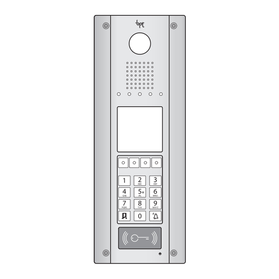
- CONTENUTO DELL'IMBALLO
- Posto esterno citofonico/videocitofonico a,
a
- Chiave a brugola b,
EN
- PACKAGING CONTENTS
- Audio/video entry control a,
- Allen wrench b,
DE
- PACKUNGSINHALT
- Außenstation Sprech-/Videosprechanlage a,
- Inbusschlüssel b,
64
145
1190 mm
DDSP VR
500 mm
100°
45 mm
870 mm
h
500 mm
5-A
1
7-A
• Caso se deseje instalar o tecto de protecção de chuva (não
) y enrosque los dos tornillos (figura
incluído) proceder como indicado na figura 4-A.
• Retirar o esquadro de bloqueio desapertando os dois parafu-
sos como indicado na figura 5-A.
) y utilice las dos
a
• Inserir a placa botoneira nos pernos colocados na base da
) para realizar las
b
caixa de encastre (figura 6-A, ponto
• Voltar a posicionar o esquadro de bloqueio no próprio lugar
(figura 6-A, punto
ponto
c
• Retirar a cobertura do borne (figura 7-A, ponto
os dois bornes amovíveis (figura 7-A, ponto
as ligações.
• Voltar a montar a cobertura do borne e fechar a placa boto-
neira.
• Fixar a placa botoneira à caixa de encastre como indicado
na figura 8-A utilizando a chave Allen fornecida.
(figura 2-A) e o posicionamento
FR
- CONTENU DE L'EMBALLAGE
- Poste extérieur d'interphonie/d'interphonie
vidéo a,
- Clé à six pans b,
ES
- CONTENIDO DEL EMBALAJE
- Placa externa de portero/videoportero
automático a,
- Llave Allen b,
PT
- CONTEÚDO DA EMBALAGEM
- Placa botoneira de porteiro/vídeo porteiro a,
- Chave allen b,
20
144
DDCI VR
1190 mm
500 mm
100°
3-A
45 mm
870 mm
1
h
500 mm
3
2
6-A
8-A
a
);
b
) e apertar os dois parafusos (figura 6-A,
).
) e utilizar
a
) para efectuar
b

Verwandte Anleitungen für Bpt DDVC/08 VR


Inhaltszusammenfassung für Bpt DDVC/08 VR
- Seite 1 BPT S.p.A. a Socio Unico Via Cornia, 1 33079 Sesto al Reghena-PN-Italy www.bpt.it-info@bpt.it PQRS WXYZ 1190 mm DDVC/08 VR – DDC/08 VR DDSI VR DDSP VR DDCI VR 500 mm 100° - INSTALLAZIONE DA INCASSO • Eliminare uno o più punti di rottura a seconda della posizione prescelta per il passaggio dei cavi (figura 1-A).
- Seite 2 - INSTALLAZIONE DA PARETE 1190 mm • Eliminare uno o più punti di rottura a seconda della posizione prescelta per il passaggio dei cavi 1190 mm (figura 1-B). 500 mm • Far passare la tubazione con i conduttori d’impianto 100° 500 mm attraverso uno dei punti a rottura (figura 2-B) utilizzando il 100°...