
Verwandte Anleitungen für Endress+Hauser nivotester FTC 4 serie


Inhaltszusammenfassung für Endress+Hauser nivotester FTC 4 serie
- Seite 1 BA 021F/00/a2/05.98 Füllstandgrenzschalter 015399-0000 nivotester FTC 420/421 Montage- und Betriebsanleitung Operating Instructions p 19…36 Endress Hauser...
-
Seite 2: Inhaltsverzeichnis
Nivotester FTC 420/421 Inhaltsverzeichnis Einleitung Meßeinrichtung Funktion Ergänzende Dokumentation Technische Daten Installation Sicherheit Montage Elektrische Verbindungen Austausch des Gerätes Abgleich Abgleich des Nivotester FTC 420 mit freier Sonde Abgleich bei bedeckter Sonde Abgleich mit Änderung des Behälterfüllstands Abgleich des Nivotester FTC 421 Störungssuche Stichwortverzeichnis Abgleich bei Maximum-Sicheheit... -
Seite 3: Einleitung
• der Elekronikeinsatz EC 61 Z und • eine Sonde, passend für das zu messende Füllgut. Es gibt eine Vielzahl von Sonden die mit dem Nivotester FTC 420 Sonden bzw. 421 betrieben werden können. Bitte nehmen Sie Kontakt mit Endress+Hauser auf; wir beraten Sie gern. -
Seite 4: Funktion
Nivotester FTC 420/421 Einleitung Funktion Sonde und Behälter bilden einen Kondensator, dessen Kapazität vom Füllstand beeinflußt wird. Der Elektronikeinsatz, der gewöhnlich im Sondenkopf eingebaut ist, setzt die Kapazitätsänderungen in ein Spannungssignal um und übermittelt dies an den Nivotester zur Auswertung. Dieser schaltet das Ausgangsrelais, wenn der vorgegebene Füllstand über- oder unterschritten wird. -
Seite 5: Technische Daten
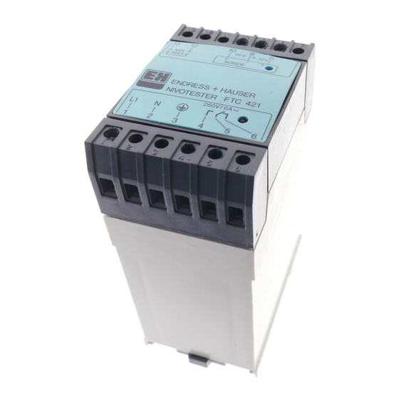
Einleitung Technische Daten Minipac-Gehäuse: grauer Kunststoff, Frontplatte blau. Mechanik • Schutzart: IP 40 • Abmessungen (T x B x H): 113 mm x 50 mm x 75 mm • Gewicht: ca. 0,3 kg • Hutschiene: nach EN 50022-35x15 oder EN 50022-35x7,5 Zulässige Umgebungstemperaturen: Umgebungstemperatur •... -
Seite 6: Installation
Nivotester FTC 420/421 Installation 2. Installation Dieses Kapitel befaßt sich mit dem mechanischen Einbau und der elektrischen Verbindung des Nivotester FTC. Fig. 3 zeigt die Front- und Rückansicht des Gerätes: • Für den Einbau des Elektronikeinsatzes und der Sonde, siehe die dazugehörende Dokumentation. Fig. -
Seite 7: Montage
Installation Montage Die Schutzart nach DIN 40050 des Gehäuses beträgt IP 40, die der Klemmblöcke IP 20. Wo möglich, sollten die Geräte in einen Schaltschrank oder an eine schattige Stelle montiert werden. Der Nivotester-Grenzschalter ist in ein Minipac-Gehäuse mit Normschiene Schnappverschluß... -
Seite 8: Elektrische Verbindungen
Nivotester FTC 420/421 Installation Schutzgehäuse Für Montage an einem staubigen oder feuchten Ort liefern wir Ih- nen ein Schutzgehäuse IP 55, in dem zwei Nivotester FTC 420 Platz haben. Siehe Fig. 5. • Montieren Sie das Schutzgehäuse an eine schattige Stelle, da die Temperatur bei einem Gerät im Innern nicht über +50 °C ansteigen darf, bei zwei Geräten max. -
Seite 9: Elektronikeinsatz
Installation Sicherheitsschaltung: ohne Brücke 12-13: Min.-Sicherheit mit Brücke: Max.-Sicherheit Signal 3…12 V NIVOTESTER Brücke 1-2 nur FTC 420/421 bei leitfähiger Masseanschluß Ansatzbildung an im Sondenkopf der Sonde Sonden- Relais- kopfgehäuse ausgang Elektronikeinsatz Sonde EC 61 Z Versorgungs- Kennfarbe: spannung Orange Fig. -
Seite 10: Maximum-Sicherheit
Nivotester FTC 420/421 Installation Sicherheitsschaltung Die Sicherheitsschaltung wird durch eine Brücke zwischen den Klemmen 12 und 13 des Nivotester gesteuert. Tabelle 1, Fig. 7 und 8 beschreiben die Funktion. Nivotester Brücke 12-13 Keine Brücke 12-13 Maximum-Sicherheit Minimum-Sicherheit FTC 420 Das Relais fällt ab, wenn Das Relais fällt ab, wenn der Füllstand den der Füllstand unter den... -
Seite 11: Austausch Des Gerätes
Installation Wenn Sie mit leitfähiger Ansatzbildung an der Sonde rechnen Ansatzbildung müssen: • Benutzen Sie eine teilisolierte Sonde, deren Isolation nahezu so lang ist wie die Sonde. • Vor dem Abgleich legen Sie eine Brücke zwischen Klemmen 1 und 2 des Elektronikeinsatzes EC 61 Z. •... -
Seite 12: Abgleich
Nivotester FTC 420/421 Abgleich 3. Abgleich Ein Abgleich wird benötigt: • Bei Inbetriebnahme des Geräts • Nach dem Austausch eines Geräts • Nach Austausch des Elektronikeinsatzes (zur Erreichung der bestmöglichen Genauigkeit) • Wenn der Behälter mit einem anderen Füllgut als beim Abgleich gefüllt wird (wesentlich andere Dielektrizitätskonstante und/oder andere Leitfähigkeit) Es gibt drei Möglichkeiten, einen Abgleich des Nivotester FTC 420... -
Seite 13: Abgleich Des Nivotester Ftc 420 Mit Freier Sonde
Abgleich Abgleich des Nivotester FTC 420 mit freier Sonde Für den nachstehenden beschriebenen Abgleich • muß der Behälter leer sein oder • darf die Sonde nicht vom Füllgut berührt werden (mindestens 100 mm von der Sondenspitze entfernt). Grüne LED Betriebsbereitschaft Hakenschalter für Einsteller Kapazitäts-Bereich... -
Seite 14: Abgleich Bei Maximum-Sicheheit
Nivotester FTC 420/421 Abgleich Bereich suchen Schalten Sie das Gerät ein. Schritt Vorgang Schließen Sie den Hakenschalter unten (Bereich I) Drehen Sie den Einsteller von einem Anschlag zum anderen und zurück - Wenn die rote Leuchtdiode dabei aufleuchtet und erlischt, weiter mit »Abgleichen bei Minimum- bzw. Maximum Sicherheit«... -
Seite 15: Abgleich Bei Bedeckter Sonde
Abgleich Abgleich bei bedeckter Sonde Dieser Abgleich ist nur möglich bei vollisolierter Sonde oder isolierendem Füllgut. • Sonde bis zum gewünschten Schaltpunkt bedecken. Zuerst den Kapazitäts-Bereich suchen, siehe dazu Seite 14. Bereich suchen Bei Minimum-Sicherheit: Abgleichen bei Minimum- Sicherheit Schritt Vorgang Drehen Sie den Einsteller vom linken Anschlag ausgehend langsam im Uhrzeigersinn, bis die rote... -
Seite 16: Abgleich Des Nivotester Ftc 421
Nivotester FTC 420/421 Abgleich Abgleich des Nivotester FTC 421 Grüne LED Betriebsbereitschaft Hakenschalter 1 für Einsteller 1: Kapazitätsbereich Schaltpunkt Hakenschalter 2 für Schaltverzögerung Einsteller 2: Rote LED Schaltverzögerung Relaiszustand Fig. 11 Abgleichelemente für Nivotester FTC 421. Abgleichelemente Fig. 11 zeigt die Abgleichelemente: •... -
Seite 17: Einstellen Der Schaltverzögerung
Abgleich Der Abgleich ist wie auf den Seiten 13 - 15 beschrieben: Abgleich Nivotester FTC 421 • »Abgleich mit freier Sonde« Seite 13, • »Abgleich bei bedeckter Sonde« Seite 15 oder • »Abgleich mit Änderung des Behälterfüllstands« Seite 15 Gehen Sie wie folgt vor: Vorgang Schritt Vorgang... -
Seite 18: Störungssuche
Nivotester FTC 420/421 Störungssuche 4. Störungssuche Normalbetrieb Ist der Nivotester FTC 420 bzw. 421 in Betrieb: • Die grüne Leuchtdiode leuchtet ständig. • Die rote Leuchtdiode leuchtet, wenn das Relais abgefallen ist, (siehe Fig. 7 und 8, Seite 10). • Bei einem Ausfall der Versorgungsspannung erlöschen die grüne und die rote Leuchtdiode;... - Seite 19 Level Limit Switch nivotester FTC 420/421 Installation and Operating Instructions Endress Hauser...
- Seite 20 Nivotester FTC 420/421 Contents Introduction Measuring system Function Supplementary documentation Technical Data Installation Safety Mounting the Nivotester Electrical connection Replacement of the Nivotester Calibration Calibration of Nivotester FTC 420 with an uncovered probe Calibration with a covered probe Calibration with a variable level Calibration of the Nivotester FTC 421 Trouble-shooting Key Words...
-
Seite 21: Introduction
• the EC 61 Z electronic insert for installation in the probe head • a probe, suitable for the medium to be measured A variety of probes are available for use with the Nivotester limit Probes switches. Endress+Hauser will be pleased to advise you on special applications. -
Seite 22: Function
Nivotester FTC 420/421 Introduction Function The probe and container (or the ground-pipe of the probe) act as a capacitor, the capacitance of which is dependent upon the level of liquid or solids present. The electronic insert, usually mounted in the probe head, passes a level-proportional voltage signal to the Nivotester for evaluation. -
Seite 23: Technical Data
Introduction Technical Data Housing: Minipac housing, light grey plastic with blue front panel Mechanical • Protection IP 40 • Dimensions: 113 mm x 50 mm x 75 mm • Weight: approx. 0.3 kg • Mounting rail: EN 50 022-35x15 or EN 50 022-35x7.5 (Top hat) Permissible temperature range Operating temperature •... -
Seite 24: Installation
Nivotester FTC 420/421 Installation 2. Installation This Chapter is concerned with the mechanical installation and electrical connection of the Nivotester FTC units. Fig. 3 gives a view of the principle connecting elements. For information on: • probe installation • installation of the EC 61 Z electronic in the probe head or separate housing, see the technical documentation supplied with these items. -
Seite 25: Mounting The Nivotester
Installation Mounting the Nivotester The degree of protection of the Nivotester housing is IP 40, that of the terminals IP 20. Where possible, the units should be mounted in a switch cabinet or shady position The limit switches use Minipac housings with snap-on fastenings suitable for switch cabinet installation on a symmetrical (top hat) rail. -
Seite 26: Electrical Connection
Nivotester FTC 420/421 Installation Installation in a protective A protective housing, degree of protection IP 55, can be supplied housing for installation in dusty or moist areas. Two units can be mounted inside, see Fig. 5: • Set up the protective housing in a shady spot where the ambient temperature does not exceed 50 °C, for two units 40 °C, or drop below -20 °C. -
Seite 27: Electronic Insert
Installation Fail-safe mode: without bridge 12-13: Min. fail-safe mode with bridge: Max. fail-safe mode Signal 3…12 V NIVOTESTER Bridge 1-2 only if Ground connection in FTC 420/421 conductive probe head deposit on probe Probe head Relay housing output Electronic insert EC 61 Z Probe Power... -
Seite 28: Fail-Safe Mode
Nivotester FTC 420/421 Installation Selection of fail-safe mode The fail-safe mode is controlled by a bridge between terminals 12 and 13 of the Nivotester. The function can be taken from Table 2, Fig. 7 and Fig. 8 Nivotester Maximum Minimum bridge 12-13 no bridge 12-13 FTC 420... -
Seite 29: Replacement Of The Nivotester
Installation A bridge must inserted between terminals 1 and 2 of the electronic Conductive build-up at the insert if there is a tendency to conductive build-up at the probe: probe • Choose a probe which is almost fully insulated • Calibrate and operate with terminals 1 and 2 of the electronic insert shorted by a bridge. -
Seite 30: Calibration
Nivotester FTC 420/421 Calibration 3. Calibration The Nivotester must be calibrated: • When the instrument is first commissioned • if the instrument substitutes an existing unit • If the electronic insert is replaced (to ensure that the best possible accuracy is attained). •... -
Seite 31: Calibration Of Nivotester Ftc 420 With An Uncovered Probe
Calibration Calibration of Nivotester FTC 420 with an uncovered probe This calibration requires that • the vessel be empty or • the liquid/solid not be in contact with the probe (at least 100 mm below its tip). Green LED Operational status Adjuster for Hook switch for switch point... -
Seite 32: Calibration For Maximum Fail-Safe Mode
Nivotester FTC 420/421 Calibration Capacitance range seeking Before proceeding, check that the green LED is lit. Procedure: Step Procedure Capacitance range seeking Turn the adjuster anticlockwise to the stop: zero setting. Select Range I at the hook switch (Table 3). Turn the adjuster clockwise through the full range and back: - If the red LED lights and extinguishes, the correct range is selected. -
Seite 33: Calibration With A Covered Probe
Calibration Calibration with a covered probe This calibration is possible with a fully insulated probe or isolating product only. • Cover the probe to the required switch point. Find the operational range by proceding as described in Capacitance range seeking »Capacitance range seeking«... -
Seite 34: Calibration Of The Nivotester Ftc 421
Nivotester FTC 420/421 Calibration Calibration of the Nivotester FTC 421 Fig. 11 Calibration controls of Nivotester FTC 421 Green LED Operational status Hook switch 1 for Adjuster 1: capacitance range Switch point Hook switch 2 for switching delay Adjuster 2: Red LED Switching delay Relay status... -
Seite 35: Switching Delay, Nivotester Ftc 421
Calibration The calibration is exactly as described on Pages 31 - 33, i.e. for Calibration procedure • an uncovered probe Nivotester FTC 421 • a covered probe or • with a variable level. Proceed as appropriate: Step Procedure Check that the time delay adjuster is at the zero position. Select the capacitance range as described on Page 32, using hook switch 1. -
Seite 36: Trouble-Shooting
(electrician’s) screwdriver: the relay in the Nivotester must switch. Endress+Hauser Sales Centers GB Tel. (01 61) 2 86 50 00, Fax (01 61) 9 98 18 41 THA Tel. (2) 9 96 78 11-20, Fax (2) 9 96 78 10 HK Tel.