Inhaltsverzeichnis
Werbung
Verfügbare Sprachen
Verfügbare Sprachen
DE
Vor dem Einbau des Ventil-Sets die Einbau-
und Betriebsanleitung vollständig lesen!
Einbau, Inbetriebnahme, Bedienung und
Wartung darf nur durch geschultes Fach-
personal durchgeführt werden!
Die Einbau- und Betriebsanleitung sowie
alle mitgeltenden Unterlagen sind an den
Anlagenbetreiber weiterzugeben!
Inhalt
1 Allgemeine Hinweise ..............................1
2 Sicherheitshinweise . ..............................2
Verpackung ...........................................3
4 Technische Daten ..................................3
5 Funktion .................................................3
6 Montage und Inbetriebnahme .................4
7 Wartung und Pflege ...............................8
8 Gewährleistung . .....................................8
OVENTROP GmbH & Co. KG
Paul-Oventrop-Straße 1
D-59939 Olsberg
Telefon
+49 (0) 29 62 82-0
Telefax
+49 (0) 29 62 82-400
E-Mail
mail@oventrop.de
Internet
www.oventrop.com
Eine Übersicht der weltweiten Ansprechpartner
finden Sie unter www.oventrop.de.
Premium Armaturen + Systeme
Einbau- und Betriebsanleitung für Fachpersonal
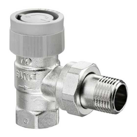
Abb.1 Ventil-Set, Eckform
1 Allgemeine Hinweise
1.1 Informationen zur Einbau- und Betriebs-
anleitung
Diese Einbau- und Betriebsanleitung dient dem
geschulten Fachpersonal dazu, das Ventil-Set
fachgerecht zu installieren und in Betrieb zu
nehmen. Mitgeltende Unterlagen - Anleitungen
aller Anlagenkomponenten sowie geltende
technische Regeln - sind einzuhalten.
1.2 Aufbewahrung der Unterlagen
Diese Einbau- und Betriebsanleitung ist vom
Anlagenbetreiber zum späteren Gebrauch
aufzubewahren.
1.3 Urheberschutz
Die Einbau- und Betriebsanleitung ist urheber-
rechtlich geschützt.
Thermostatventil-Set
Technische Änderungen vorbehalten.
171306380 05/2019
1
Werbung
Kapitel
Inhaltsverzeichnis

Verwandte Anleitungen für oventrop AQ


Inhaltszusammenfassung für oventrop AQ
-
Seite 1: Inhaltsverzeichnis
5 Funktion ..........3 anleitung 6 Montage und Inbetriebnahme ....4 Diese Einbau- und Betriebsanleitung dient dem geschulten Fachpersonal dazu, das Ventil-Set 7 Wartung und Pflege .......8 fachgerecht zu installieren und in Betrieb zu 8 Gewährleistung ........8 nehmen. Mitgeltende Unterlagen – Anleitungen aller Anlagenkomponenten sowie geltende technische Regeln – sind einzuhalten. 1.2 Aufbewahrung der Unterlagen OVENTROP GmbH & Co. KG Diese Einbau- und Betriebsanleitung ist vom Paul-Oventrop-Straße 1 Anlagenbetreiber zum späteren Gebrauch aufzubewahren. D-59939 Olsberg Telefon +49 (0) 29 62 82-0 1.3 Urheberschutz Telefax +49 (0) 29 62 82-400 Die Einbau- und Betriebsanleitung ist urheber- E-Mail mail@oventrop.de... -
Seite 2: Sicherheitshinweise
2 Sicherheitshinweise 1.4 Symbolerklärung Hinweise zur Sicherheit sind durch Symbole 2.1 Bestimmungsgemäße Verwendung gekennzeichnet. Diese Hinweise sind zu be- Die Betriebssicherheit ist nur bei bestimmungs- folgen, um Unfälle, Sachschäden und gemäßer Verwendung der Armatur gewähr- Störungen zu vermeiden. leistet. Das Ventil-Set, bestehend aus Thermostatven- til „AQ“, Verschraubung „Combi 2“ und GEFAHR Thermostat „vindo TH“, wird in Zentralheizungs- GEFAHR weist auf eine unmittelbar oder Kühlanlagen mit geschlossenen Kreisläufen gefährliche Situation hin, die zum Tod oder zur Regelung der Raumtemperatur und zur zu schweren Verletzungen führen wird, automatischen Durchflussregelung (hy- wenn die Sicherheitsmaßnahmen nicht draulischer Abgleich) eingesetzt. -
Seite 3: Transport, Lagerung Und Verpackung
3 Transport, Lagerung und Thermostatventil „AQ“: Einstellbereich: 10 – 170 l/h Verpackung Die Einstellwerte sind von außen direkt 3.1 Transportinspektion ablesbar (ohne Tabelle). Lieferung unmittelbar nach Erhalt sowie vor Regelbereich: Einbau auf mögliche Transportschäden und ∆p max.: 1,5 bar Vollständigkeit untersuchen. Falls derartige ∆p min. (10-130 l/h): 0,1 bar oder andere Mängel feststellbar sind, Wa- ∆p min. (>130-170 l/h): 0,15 bar rensendung nur unter Vorbehalt annehmen. Unterhalb von ∆p min. ist eine normale Reklamation einleiten. Dabei Reklamationsfris-... -
Seite 4: Montage Und Inbetriebnahme
4 Bauschutzkappe schraubt und anschließend der Differenzdruck 5 Überwurfmutter 6 Auslass mit der Differenzdruckmessspindel gemessen ∆p Differenzdruck werden. Sobald der gemessene Differenzdruck gleich oder größer als der Differenzdruck ∆p min. (siehe 4.1) ist, steht ausreichend Dif- ferenzdruck für die automatische Durchfl ussre- gelung des Ventils zur Verfügung. Anschließend den Ventileinsatz wieder in das Ventilgehäuse einschrauben und alle Montage- stellen auf Dichtheit überprüfen. ACHTUNG Das Drehmoment für das Festschrauben Abb. 2 Aufbau Ventil „AQ“ des Ventileinsatzes beträgt 15 Nm. Zur Ventileinsatzmontage bzw. Die Verschraubung „Combi 2“ mit Absperrung –demontage Schlüssel SW 19 benutzen. ermöglicht die Demontage des Heizkörpers, ohne Entleeren der Anlage. 5.3 Geräuschverhalten Zur zusätzlichen Regelung der Raumtempera- Für einen geräuscharmen Betrieb in Verbindung tur bildet der Thermostat „vindo TH“ gemeinsam mit einer geräuschsensiblen Anlageninstallation mit dem Ventil einen ohne Hilfsenergie arbeit- (z.B. Heizkörper) sollte der max. Differenzdruck enden Proportionalregler. über dem Ventil 600 mbar nicht überschreiten. -
Seite 5: Rohrleitungsmontage Für Genormte
P rüfen Sie vorab, ob die Funktion der Metall- und Kunststoffrohre Klemmringverschraubung gewährleistet ist. Für die Verbindung genormter Rohre aus Kupfer, Edelstahl, Präzisionsstahl und Kunst- ACHTUNG stoff an das Thermostatventil und die Ver- Bei der Montage kein zusätzliches Fett schraubung sind bei Oventrop für verschiedene oder Öl verwenden, da es die Verbindungsarten (z.B. Schrauben) die Dichtungsmaterialien im Ventil angreift. Verbindungselemente zu beziehen (Zubehör, Die Einzelteile sind bereits werksseitig siehe Katalog „Ofix“ Verbindungstechnik). Rohre geölt. -
Seite 6: Absperren Der Verschraubung
Klemmring- verschraubungen beachten. Einstellmarkierung 6.2 Inbetriebnahme 6.2.1 Hinweise zur Bauschutzkappe Das Thermostatventil wird werksseitig mit einer Bauschutzkappe aus Kunststoff ausgeliefert. Sie schützt zum einen die Ventilspindel, zum Einstellwert x anderen kann mit ihr während der Bauphase 10 [l/h] = 170 l/h das Thermostatventil manuell eingestellt Abb. 3 Voreinstellung Thermostatventil „AQ“ werden. 6.2.3 Absperren der Verschraubung ACHTUNG 1. Schutzkappe abschrauben. 2. V entilkegel mit dem Sechskantschlüssel SW Die Bauschutzkappe darf nicht zur 6 (1) durch Rechtsdrehen schließen (Abb. Absperrung des Thermostatventils gegen Umgebungsdruck (z.B. bei demontiertem Heizkörper) verwendet werden. Die hohen Rückstellkräfte der Ventilspindel würden die Bauschutzkappe beschädigen. - Seite 7 6.3 Montage des Thermostaten 6.3.1 Thermostat Begrenzen und Blockieren Der Einstellbereich des Thermostaten kann ACHTUNG mittels der im Handrad befindlichen Begren- zungselemente auf jedem Teilstrich, jeder Thermostaten erst montieren, wenn die Merkzahl und der Frostschutzstellung begrenzt Bauphase abgeschlossen ist, um oder blockiert werden. Beschädigungen am Thermostaten zu vermeiden. Begrenzen (z. B. zwischen Merkzahl „2“ und „4“) 1. Thermostat auf „5“ stellen. 1. S chieben Sie mittels eines geeigneten 2. T hermostat so ausrichten, dass die Mark- Werkzeuges oder Stiftes die Begrenzungsele- ierung gut sichtbar ist.
-
Seite 8: Wartung Und Pflege
2. D ie beiden Elemente aus der „Parkposition“ des Ventileinsatzes beträgt 15 Nm. herausschieben und in die Position rechts Zur Ventileinsatzmontage bzw. und links von der Einstellmarke einstecken –demontage Schlüssel SW 19 benutzen. (Abb. 9). 8 Gewährleistung Es gelten die zum Zeitpunkt der Lieferung gültigen Gewährleistungsbedingungen von Oventrop. Abb. 9 Zur Aufhebung der Begrenzung oder Blockierung die Elemente jeweils herausschieben und wieder in die „Parkposition“ einstecken. 7 Wartung und Pflege Die Armaturen sind wartungsfrei. Bei Funk- tionsstörungen sind Wartungsarbeiten erforder- lich. Eine gute Zugänglichkeit der Armaturen wird empfohlen. Der Ventileinsatz (Pos. 2, Abb. 2) ist ohne Entleeren der Anlage mittels „Demo-Bloc“ aus... -
Seite 9: General Information
6 Installation and initial operation ....12 valve set professionally and to put it into operation. 7 Maintenance ........16 Other valid documents – manuals of all system 8 Warranty. ..........16 components as well as valid technical rules – must be observed. 1.2 Keeping of documents The installation and operating instructions should be kept by the user of the system for later reference. 1.3 Copyright The installation and operating instructions are copyrighted. Subject to technical modifications without notice. For an overview of our global presence visit www.oventrop.de. 171306380 05/2019... -
Seite 10: Symbol Explanation
2 Safety notes 1.4 Symbol explanation Safety guidelines are displayed by symbols. 2.1 Correct use These guidelines are to be observed to avoid Safety in operation is only guaranteed if the accidents, damage to property and malfunctions. thermostatic valve set is used correctly. The valve set consisting of a thermostatic valve “AQ”, a radiator lockshield valve “Combi 2” DANGER and a thermostat “vindo TH” is used in central DANGER indicates an imminent dangerous heating or cooling systems with closed circuits situation which will lead to death or serious for room temperature control and for automatic injury if the safety guidelines are not flow control (hydronic balancing). observed. Any use of the thermostatic valve set outside the above application will be considered as non-compliant and misuse. Claims of any kind WARNING against the manufacturer and/or his authorised WARNING indicates a possible dangerous representatives, regarding damages caused situation which may lead to death or by incorrect use, cannot be accepted. -
Seite 11: Transport, Storage And Packaging
3 Transport, storage and Thermostatic valve “AQ”: Control range: packaging The set values are visible from outside (without 3.1 Transport inspection table). Upon receipt check delivery for any damages Control range: caused during transit and completeness. ∆p max.: 1.5 bar Any damage must be reported immediately ∆p min. (10-130 l/h): 0.1 bar upon receipt. ∆p min. (>130-170 l/h): 0.15 bar A normal thermostatic valve function is given 3.2 Storage below ∆p min., i.e. the set flow rate is under- The thermostatic valve set must only be stored cut depending on the differential pressure. under the following conditions: – D o not store in open air, keep dry and free Radiator lockshield valve “Combi 2”: from dust. -Wert: 1.70 m³/h – D ot not expose to aggressive fluids or heat Dimensions: sources. -
Seite 12: Differential Pressure Measurement
∆p Differential pressure measuring stem. As soon as the measured differential pressure has reached or exceeded the differential pressure ∆p min. (see 4.1), the differential pressure is high enough for an automatic fl ow control of the valve. Screw the valve insert into the valve body again and check all installation points for leaks. NOTICE The valve insert is tightened with a torque of 15 Nm. Illustr. 2 Construction thermostatic valve “AQ” Use a 19 mm spanner for mounting or dismounting the valve insert. The radiator lockshield valve “Combi 2” allows for the removal of the radiator without draining 5.3 Noise behaviour the system. For a silent operation in combination with an The thermostat “vindo TH” together with the installation which is sensitive to noise (e.g. thermostatic valve is also a proportional radiators), the maximum differential pressure controller for room temperature control working across the valve should not exceed 600 mbar. - Seite 13 6.1.4 Pipework installation for valve. composition pipes The thermostatic valve and radiator lockshield NOTICE valve can also be connected to the pipework When using compression fittings for female with the help of composition pipes. The threaded radiator fittings (sized DN 10, connection systems of the manufacturers have 15, 20), the “Ofix” compression fittings to be used. When using the Oventrop have to be used to guarantee a perfect composition pipe “Copipe”, connection of the sealing function between the pipework valves has to be carried out with the help of and the valve. the “Cofit” fittings. Item no. 10271../10281..
-
Seite 14: Initial Operation
6.2.1 Advice regarding the protection cap The thermostatic valve is supplied with a plastic protection cap. It protects the valve stem and can be used for the manual setting of the Set value x thermostatic valve during the construction 10 [l/h] = 170 l/h period. Illustr. 3 Setting of the thermostatic valve “AQ” NOTICE 6.2.3 Isolation of the radiator lockshield valve The protection cap must not be used for permanent shut-off of the thermostatic 1. Remove the protection cap. valve against system pressure (for instance 2. C lose the valve disc by turning a while the radiator is removed). The high... - Seite 15 6.3 Installation of the thermostat 6.3.1 Limitation and locking of the thermostat The control range of the thermostat can be NOTICE limited and locked to any graduation line, figure or the frost protection symbol with help of the Do not fit the thermostat until all building limiting clips which can be found inside the work has been completed to avoid damage handwheel. to the thermostat. Limitation 1. Set the thermostat to position “5”. for instance between figure “2” and “4”) 2. A lign the thermostat so that the indicator 1. S lide the limiting clips out of the “parking mark is clearly visible. position” (between figure “5” and “0”, illustr. 3. H old in this position and tighten the collar 6) with the help of a suitable tool or pin. nut (do not use excessive force). Set the thermostat to the required room temperature (illustr. 5).
-
Seite 16: Maintenance
Locking NOTICE (for instance position “3”) 1. Turn the thermostat to position “3”. The valve insert is tightened with a torque 2. S lide the limiting clips out of the “parking of 15 Nm. position” and push them into the grooves Use a 19 mm spanner for mounting or immediately before and after figure “3” dismounting the valve insert. (illustr. 9). 8 Warranty Oventrops warranty conditions valid at the time of supply are applicable. Illustr. 9 The limitation and locking can be cancelled at any time by sliding the limiting clips out of the grooves and by fitting them back into the “parking position”. 7 Maintenance The components of the set are maintenance- free. The products have to be serviced if they malfunction. The components must be easily accessible. -
Seite 17: Indicazioni Generali
4 Dati tecnici ..........19 sono rivolte al personale qualificato, che dovrà 5 Funzionamento ........19 occuparsi dell’installazione e della messa in 6 Installazione e messa in servizio ..20 servizio del set TRV. Altri documenti validi da osservare: le istruzioni 7 Manutenzione ........24 relative ai componenti dell’impianto, nonché 8 Garanzia ..........24 le normative tecniche in vigore. 1.2 Conservazione dei documenti Le istruzioni di installazione e funzionamento devono essere conservate dall’utilizzatore dell’impianto per eventuale uso futuro. 1.3 Tutela dei diritti d’autore Le istruzioni per l’uso e l’installazione sono protette da copyright. Per una panoramica della nostra presenza a Salvo modifiche tecniche senza notifica. livello mondiale visitare la pagina www.oventrop.de. 171306380 05/2019... -
Seite 18: Legenda Dei Simboli
2 Avvisi di sicurezza 1.4 Legenda dei simboli Le avvertenze riguardanti la sicurezza sono 2.1 Utilizzo conforme contrassegnate da simboli. Questi avvisi devono La sicurezza nel funzionamento del set TRV essere rispettati, per evitare infortuni, danni può essere garantita soltanto da un utilizzo materiali e guasti. conforme. Il set TRV, costituito da una valvola PERICOLO termostatizzabile “AQ”, un detentore “Combi 2” e una testa termostatica “vindo TH”, può PERICOLO viene visualizzato in una essere utilizzato in impianti di riscaldamento situazione di pericolo imminente, che può o raffrescamento centralizzati a circuito chiuso, causare la morte o gravi lesioni, ove non per il controllo della temperatura ambiente e siano state rispettate le misure di sicurezza. per la regolazione automatica delle portate (bilanciamento idraulico). È vietata ogni forma di utilizzo diversa da quelle AVVERTIMENTO summenzionate ed è considerata non conforme... -
Seite 19: Trasporto, Stoccaggio E Imballaggio
3 Trasporto, stoccaggio e Valvola termostatizzabile “AQ”: Campo di regolazione: 10 - 170 l/h imballaggio I valori impostati sono leggibili direttamente 3.1 Ispezione del trasporto dall’esterno (senza tabella). Al ricevimento della fornitura verificarne la Campo di regolazione: completezza ed eventuali danni causati dal ∆p max.: 1,5 bar trasporto. ∆p min. (10-130 l/h): 0,1 bar Eventuali danni devono essere segnalati ∆p min. (>130-170 l/h): 0,15 bar immediatamente in fase di ricezione. Al di sotto del valore minimo di ∆p il funzionamento è quello di una normale valvola 3.2 Stoccaggio... -
Seite 20: Installazione E Messa In Servizio
2) con il “Demo-Bloc” e poi misurare la pressione differenziale con l’apposito ago di misurazione della pressione differenziale. Non appena la pressione differenziale misurata risulta uguale o maggiore rispetto alla pressione differenziale ∆p minima (si veda 4.1), sarà stata raggiunta una pressione differenziale suffi ciente al controllo automatico della portata sulla valvola. Avvitare nuovamente il vitone nel corpo valvola e controllare la tenuta di tutti i punti di collegamento. Fig. 2 Struttura della valvola termostatizzabile AVVERTENZA “AQ” Il vitone deve essere serrato con una coppia di 15 Nm. Il detentore “Combi 2” consente di smontare Utilizzare una chiave aperta da 19mm per il radiatore senza scaricare l’impianto. montare o smontare il vitone. La testa termostatica “vindo TH” insieme alla valvola termostatizzabile, funziona da regolatore 5.3 Silenziosità proporzionale per il controllo della temperatura Per un funzionamento silenzioso su impianti ambiente, funzionamento senza energia sensibili al rumore (ad es. radiatori) la pressione... - Seite 21 I n quel caso, rispettare le raccomandazioni fornite dal produttore del tubo. 6.1.3 Installazione delle tubazioni con tubi V erificare prima di tutto che siano garantiti standard in metallo e in plastica i collegamenti con raccordi di serraggio. Oventrop dispone di raccordi per diversi tipi di collegamenti (ad es. attacchi filettati) per tubi standard in rame, acciaio inox, acciaio di ATTENZIONE precisione e plastica alla valvola termostatizzabile Durante la fase di installazione non e al detentore (Accessori, si veda il catalogo utilizzare grassi od olii aggiuntivi, in quanto “Ofix” alla sezione tecniche di collegamento).
-
Seite 22: Messa In Servizio
La valvola termostatizzabile viene consegnata dal fabbricante con un cappuccio di protezione di plastica in dotazione. Esso consente da un lato di proteggere lo stelo della valvola, dall’altro di poter regolare manualmente la valvola Valore impostato x termostatizzabile durante la fase di costruzione. 10 [l/h] = 170 l/h AVVERTENZA Fig. 3 Preregolazione della valvola termostatizzabile “AQ” Il cappuccio di protezione non deve essere utilizzato per una intercettazione 6.2.3 Intercettazione del detentore a servizio permanente della valvola contro la del radiatore pressione dell’impianto (ad es. in caso di 1. Rimuovere il cappuccio di protezione. rimozione del radiatore). L’elevata forza 2. C hiudere l’otturatore conico con una chiave... - Seite 23 6.3 Installazione della testa termostatica 6.3.1 Limitazione e blocco della testa termostatica ATTENZIONE Il campo di regolazione della testa termostatica può essere limitato o bloccato a vari livelli di Non installare la testa termostatica fino gradazione, numeri distintivi (impostazioni) o ad ultimazione dei lavori sull’intero cantiere simbolo di protezione antigelo, tramite appositi al fine di evitare danneggiamenti alla testa componenti di limitazione (cavalieri) presenti termostatica. dentro il volantino. 1. I mpostare la testa termostatica sulla Limitazione posizione “5”. per esempio tra l’impostazione “2” e “4” 2. A llineare la testa termostatica in modo che 1. F ar scorrere le clip di limitazione dalla l’indicatore di riferimento della posizione sia “posizione di sicura” (tra il numero di ben visibile.
-
Seite 24: Manutenzione
1. Impostare il termostato sulla posizione “3”. Il vitone deve essere serrato con una coppia 2. S postare entrambe le clip di limitazione dalla di 15 Nm. “posizione di sicura” e inserirli nelle sedi Utilizzare una chiave aperta da 19mm per subito a destra e a sinistra dell’indicatore montare o smontare il vitone. dell’impostazione “3” (Fig. 9). 8 Garanzia Sono valide le condizioni di garanzia stabilite da Oventrop e in vigore al momento della fornitura. Fig. 9 La limitazione e il blocco possono essere rimossi in ogni momento: fare scorrere nuovamente le clip, rimuovendole dalle sedi e riposizionarle sulla “posizione di sicura”. 7 Manutenzione I componenti del set non richiedono manutenzione. Effettuare lavori di manutenzione in caso di malfunzionamenti sul prodotto. Si consiglia di garantire facile accesso ai componenti. -
Seite 25: Información General
Otros documentos válidos – manuales de todos 7 Mantenimiento ........32 los componentes del sistema, así como la 8 Garantía ..........32 normativa técnica vigente. 1.2 Guardado de documentos Estas instrucciones de instalación y funcionamiento deberán permanecer con el usuario del sistema para consulta posterior. 1.3 Copyright Estas instrucciones de instalación y funcionamiento están sujetas a copyright. Sujeto a modificaciones técnicas sin aviso. Para una visión general de nuestra presencia global visite www.oventrop.es 171306380 05/2019... -
Seite 26: Explicación De Símbolos
2.1 Uso correcto mediante símbolos. Estas indicaciones deben La seguridad del funcionamiento solo se respetarse para evitar accidentes, daños a la garantiza si el kit de válvula termostática se propiedad y fallos de funcionamiento. usa correctamente. El kit de válvula termostática, compuesto por ¡PELIGRO! una válvula termostática “AQ”, un detentor “Combi 2” y un cabezal termostático “vindo PELIGRO indica una inminente situación TH”, está diseñado para sistemas centralizados de peligro que puede conllevar la muerte de calefacción y refrigeración con circuitos o daño severo si no se respetan las cerrados de agua para el control de la instrucciones de seguridad. temperatura ambiente y el control automático de caudal (equilibrado hidráulico). -
Seite 27: Transporte, Almacenamiento
3 Transporte, almacenamiento Válvula Termostática “AQ” Rango de control: y empaquetado ∆p max.: 1.5 bar 3.1 Inspección del transporte ∆p min. (10-130 l/h): 0.1 bar Tras la recepción, comprobar los posibles daños ∆p min. (>130-170 l/h): 0.15 bar causados durante el transporte. Por debajo de la ∆p min. se da un funcionamiento Cualquier daño debe notificarse inmediatamente de válvula termostática normal, ej. el caudal tras la recepción. ajustado se reduce dependiendo de la presión diferencial. 3.2 Almacenamiento Detentor “Combi 2”: El kit de válvula termostática debe almacenarse Valor k 1.70 m³/h en las siguientes condiciones: – N o almacenar a la intemperie, mantener en Dimensiones: lugar seco y libre de suciedad. Válvula termostática según EN215, series D – N o exponer a fluidos agresivos o fuentes de “Combi 2” según DIN 3842... -
Seite 28: Instalación Y Puesta En Marcha
“Demo-Bloc” y mida la presión ∆p Presión diferencial diferencial usando el eje de medición de presión diferencial. Tan pronto como la presión diferencial medida ha alcanzado o superado el valor de presión diferencial mínimo ∆p min. (ver 4.1), la presión diferencial es sufi cientemente alta para un control automático del caudal por parte de la válvula. Rosque, de nuevo, la montura de la válvula sobre su cuerpo e inspeccione la instalación por si hubiera alguna fuga. ¡NOTA! Fig. 2 Construcción de la válvula termostática “AQ” La montura de la válvula está ensamblada con un par de 15 Nm. El detentor “Combi 2” permite retirar el radiador Utilice una llave de 19 mm para montar o sin tener que vaciar el sistema. desmontar la montura de la válvula. El cabezal termostático “vindo TH” junto con la válvula termostática actúa también como un 5.3 Comportamiento frente al ruido controlador proporcional para el control de la Para un funcionamiento silencioso en temperatura ambiente sin energía auxiliar. combinación con una instalación sensible al ruido (ej., radiadores), la máxima presión... - Seite 29 3. L os refuerzos de tubo no pueden ser utilizada fácilmente accesible. en tuberías con costuras soldadas. Deben seguirse las recomendaciones del fabricante 6.1.3 Instalación de tubería para tubería de tubería. Comprobar si el funcionamiento metálica o plástica del accesorio de compresión está Oventrop ofrece elementos de conexión para garantizado. los diferentes tipos de conexión (ej. conexión roscada) de cobre estándar, acero inoxidable, acero de precisión y tubería plástica a las ¡NOTA! válvulas termostáticas y a los detentores No deben usarse agentes lubricantes o (accesorios, ver catálogo, Sistemas de Conexión...
-
Seite 30: Puesta En Marcha
6.2 Puesta en marcha 6.2.1 Recomendaciones sobre el tapón protector La válvula termostática se suministra con un Caudal de ajuste x tapón protector de plástico. Protege el eje de 10 [l/h] = 170 l/h la válvula y puede utilizarse para el ajuste manual de la válvula durante la instalación. Fig. 3: Ajuste de la válvula termostática “AQ” 6.2.3 Corte del detentor ¡NOTA! 1. Retire la tapa protectora El tapón protector no debe utilizarse para 2. C ierre el disco de la válvula girando una llave el cierre permanente de la válvula (6 mm) en el sentido de las agujas del reloj termostática contra la presión del sistema (fig. 4) - Seite 31 6.3 Instalación del termostato 6.3.1 Limitación y bloqueo del termostato El rango de control del cabezal termostático ¡NOTA! puede limitarse y bloquearse a cualquier valor o en el símbolo de protección contra la No instale el cabezal termostático hasta congelación con la ayuda de los clips limitadores que todos los trabajos en el edificio hayan que se encuentran en el interior del volante. sido terminados para evitar posibles daños en el cabezal. Limitación Por ejemplo, entre los valores “2” y “4” 1. Ajuste el cabezal a la posición “5” 1. D eslice los clips limitadores fuera de su 2. A linee el cabezal de manera que la marca posición original (entre el valor “5” y “0”, del indicador sea claramente visible. fig. 6) con la ayuda de una herramienta 3. S ujételo en esa posición y apriete la tuerca adecuada o un pin.
-
Seite 32: Mantenimiento
“3” con un par de 15 Nm. 2. D eslice los clips limitadores fuera de su Utilice una llave de 19 mm para montar o posición original e introdúzcalos en los ori- desmontar la montura de la válvula. ficios inmediatamente anterior y posterior del valor “3” (fig. 9). 8 Garantía Se aplicarán las condiciones de garantía de Oventrop válidas en el momento del suministro. Fig. 9 La limitación y el bloqueo pueden ser anulados en cualquier momento deslizando los clips limitadores fuera de los orificios y volviéndolos a alojar en su posición original. 7 Mantenimiento Los componentes del kit no precisan mantenimiento. Los productos podrán precisar mantenimiento si su funcionamiento no es correcto. Los componentes del kit deberán ser... -
Seite 33: Obecné Informace
5 Funkce ..........35 provozních podmínkách 6 Montáž a uvedení do provozu ....36 Tyto instalační a provozní pokyny k obsluze 7 Servis a údržba ........40 jsou určeny pro proškolené pracovníky, jak správně nainstalovat sadu ventilu a uvést do 8 Záruka ..........40 provozu. Je potřeba dodržovat platné dokumenty a pokyny pro všechny komponenty systému. 1.2 Uchování dokumentace Tento návod pro použití by měl být zachován pro budoucí použití provozovatelem zařízení. 1.3 Ochrana autorských práv Instalace a provoz jsou chráněny autorskými právy. Technické změny vyhrazeny. Přehled partnerů ve světě naleznete na www.oventrop.de. 171306380 05/2019... -
Seite 34: Vysvětlení Symbolů
2 Bezpečnostní podmínky 1.4 Vysvětlení symbolů Bezpečnostní pokyny jsou označeny symboly. 2.1 Správné používání a rozsah používání Tyto pokyny jsou určeny pro používání, aby Je zaručena bezpečnost provozu pouze tehdy, se zabránilo nehodám, škodám na majetku a pokud je používání armatur dle pokynů. Sada poruchám. ventilů, složená z termostatického ventilu „AQ“, šroubení „Combi 2“ a termostatické hlavice „vindo TH“, je používána pro vytápění NEBEZPEČÍ a chlazení s uzavřenými okruhy pro regulaci NEBEZPEČÍ upozornění na bezprostředně prostorové teploty a pro automatickou regulaci hrozící nebezpečí při nedodržování průtoku (hydraulické vyvážení). bezpečnostních pokynů. Mohlo by dojít Je nepřípustné používat sadu ventilů pro další k úmrtí nebo vážnému zranění. a /nebo odlišné účely, než pro které jsou určeny. Veškeré nároky vůči výrobci při... -
Seite 35: Doprava, Skladování A Obaly
3 Doprava, skladování a obaly Termostatický ventil „AQ“ Rozsah nastavení: 10 – 170 l/h 3.1 Kontrola přepravy Hodnoty nastavení lze číst zvenku přímo Dodávku je potřeba ihned po obdržení a před (bez tabulky). instalací zkontrolovat. Rozsah regulace: Zjistit úplnost dodávky a zjistit případné škody. ∆p max.: 1,5 bar V případě zjištěných nedostatků nebo jiných ∆p min. (10-130 l/h): 0,1 bar vad je potřeba zásilku reklamovat. Je potřeba ∆p min. (>130-170 l/h): 0,15 bar dodržet dobu reklamace. V případě nižší tlakové diference ∆p min. je zajištěna normální funkce termostatického 3.2 Skladování ventilu, může však dojít ke snížení průtoku Sadu ventilů skladovat za následujících pod požadovanou hodnotu. -
Seite 36: Montáž A Uvedení Do Provozu
6 odtok je změřený diferenční tlak rovný, nebo větší ∆p diferenční tlak než požadovaný min. diferenční tlak Δp (viz 4.1) pak bude automatická regulace průtoku ventilem funkční. Potom se vložka ventilu našroubuje zpět do ventilu a přezkouší se na těsnost. POZOR Otáčecí moment pro následné utažení vložky ventilu je 15 Nm. Pro montáž ventilové vložky nebo její demontáž je potřeba použít klíč SW 19. Obr. 2 Konstrukce ventilu „AQ“ 5.3 Hlukové vlastnosti Šroubení „Combi 2“ s proporcionálním jemným Pro bezhlučný provoz ve spojení s na hluk přednastavením a uzavíráním umožňuje citlivými zařízeními (například radiátory) by demontáž otopného systému bez vypouštění maximální tlaková diference ventilu neměla soustavy. Termostatická hlavice „vindo TH“ překročit 600 mbar. a termostatické ventily tvoří společně proporcionální regulátory pracující bez pomocné energie. 6 Montáž a uvedení do provozu Před osazením ventilu a šroubení do potrubního... - Seite 37 3. P ři používání trubek svařovaných 6.1.3 Instalace standardních kovových a nepoužívejte opěrná pouzdra. plastových trubek P řed použitím si zkontrolujte pokyny od Pro připojení standardních měděných trubek výrobců potrubí. Zkontrolujte, zda lze použít z nerezové oceli, přesných ocelových trubek šroubení se svěrným kroužkem. a plastového potrubí na termostatické ventily a šroubení se používají různé druhy připojení POZOR firmy Oventrop (např. šroubení) a různé druhy připojovacích prvků (příslušenství, spojovací Při instalaci nesmí být použity žádné tuky součásti „Ofix“ viz katalog). Potrubí z oceli se nebo oleje, protože může dojít k poškození těsnění. do termostatických ventilů namontuje přímo. Jednotlivé díly jsou již naolejované z výroby. POZOR Při použití šroubení se svěrným kroužkem 6.1.4 Instalace vícevrstvého plastového pro armatury pro vytápění s vnitřním...
-
Seite 38: Uvedení Do Provozu
6.2.1 Pokyny pro používání ochranné krytky Termostatický ventil je z výroby vybaven ochrannou krytkou z plastu. Chrání vřeteno ventilu, kterým lze zdvih v průběhu výstavby nastavit ručně. označení x 10 [l/h] = 170 l/h POZOR Obr. 3 Přednastavení termostatického ventilu Ochranný kryt se nesmí použít pro „AQ“ uzavírání termostatického ventilu proti okolnímu tlaku (např. při demontáži 6.2.3 Nastavení šroubení otopného tělesa). Vysoká vratná síla na 1. Odšroubovat ochrannou krytku. vřetenu ventilu by ochranný kryt poškodila 2. K uželku ventilu uzavřít pomocí šestihranného a voda z ventilu vytekla! klíče SW 6 (1) otáčením ve směru hodinových Na hrdle výstupu namontujte ocelové... - Seite 39 6.3 Montáž termostatických hlavic 6.3.1 Omezování a blokování termostatických hlavic POZOR Nastavení termostatických hlavic lze provádět ručně pomocí omezovacího prvku na Termostatické hlavice namontujte až po požadovanou rysku s označením. Touto funkcí dokončení stavby, aby nedošlo k jejich je zajištěna ochrana proti zamrznutí. poškození. Omezení 1. Termostatickou hlavici nastavte na „5“. (např. mezi označením „2“ a „4“) 2. T ermostatickou hlavici vyrovnejte tak, aby 1. P osuňte omezovací prvek pomocí vhodného označení bylo dobře viditelné. nástroje z „parkovací pozice“ (mezi označení 3. P řidržte pevně v této poloze a utáhněte „5“ a „0“, obr. 6). převlečnou matici (bez použití násilí). Na závěr nastavte termostatickou hlavici na požadovanou hodnotu teploty v místnosti (obr. POZOR Při montáži termostatické hlavice Obr.
-
Seite 40: Údržba A Péče
Blokování UPOZORNĚNÍ (např. nastavení „3“) 1. Termostatickou hlavici otočte na „3“. Utahovací moment pro následné utažení 2. O ba omezovací prvky posuňte z „parkovací vložky ventilu je 15 Nm. polohy“ doleva nebo doprava od nastavené Pro montáž ventilové vložky nebo její hodnoty (Obr. 9). demontáž je potřeba použít klíč SW 19. 8 Záruka Záruční podmínky firmy Oventrop jsou platné od okamžiku dodání výrobku. Obr. 9 Pro uvolnění omezení nebo blokování posuňte blokovací prvky a zase nastavte do „parkovací polohy“. 7 Údržba a péče Armatury jsou bezúdržbové. V případě poruchy je nutné provést údržbové práce. Je vhodné zachovat snadný přístup k armatuře. V tomto případě je potřeba ventilovou vložku (poz. 2, obr. 2) pomocí nástroje „Demo-Bloc“ vyšroubovat (poz. 1, obr. 2).