Inhaltsverzeichnis
Werbung
Verfügbare Sprachen
Verfügbare Sprachen
Werbung
Inhaltsverzeichnis

Verwandte Anleitungen für EuroLite LED IP T-PIX 12 HCL


Inhaltszusammenfassung für EuroLite LED IP T-PIX 12 HCL
-
Seite 2: Inhaltsverzeichnis
Diese Bedienungsanleitung gilt für die Artikelnummer / This user manual is valid for the article number: 51914111 Das neueste Update dieser Bedienungsanleitung finden Sie im Internet unter: You can find the latest update of this user manual in the Internet under: www.eurolite.de 2/36 00126414, Version 1.0... -
Seite 3: Einführung
BEDIENUNGSANLEITUNG LED IP T-PIX 12 HCL Leiste GEFAHR! Elektrischer Schlag durch Kurzschluss Seien Sie besonders vorsichtig beim Umgang mit gefährlicher Netzspannung. Bei dieser Spannung können Sie einen lebensgefährlichen elektrischen Schlag erhalten. Öffnen Sie das Gerät niemals. Lesen Sie vor der Verwendung des Geräts diese Bedienungsanleitung. Sie erhalten dadurch wichtige Hinweise für den korrekten Betrieb. -
Seite 4: Sicherheitshinweise
SICHERHEITSHINWEISE WARNUNG! Lesen Sie aufmerksam die Sicherheitshinweise und benutzen Sie das Produkt nur wie in dieser Anleitung beschrieben, damit es nicht versehentlich zu Verletzungen oder Schäden kommt. Verwendungszweck • Das Produkt dient zur Beleuchtung im Innen- und Außenbereich und ist nach IP65 aufgebaut. Es darf im Betrieb im Innen- und Außenbereich montiert und betrieben werden und ist nicht dimmbar. - Seite 5 Warnung vor Verbrennung und Brand • Der zulässige Umgebungstemperaturbereich (Ta) beträgt -5 bis +45 °C. Verwenden Sie das Gerät niemals außerhalb dieses Temperaturbereichs. • Die Gehäusetemperatur (Tc) kann im Betrieb bis zu 60 °C betragen. Vermeiden Sie den Kontakt mit Personen oder Gegenständen.
-
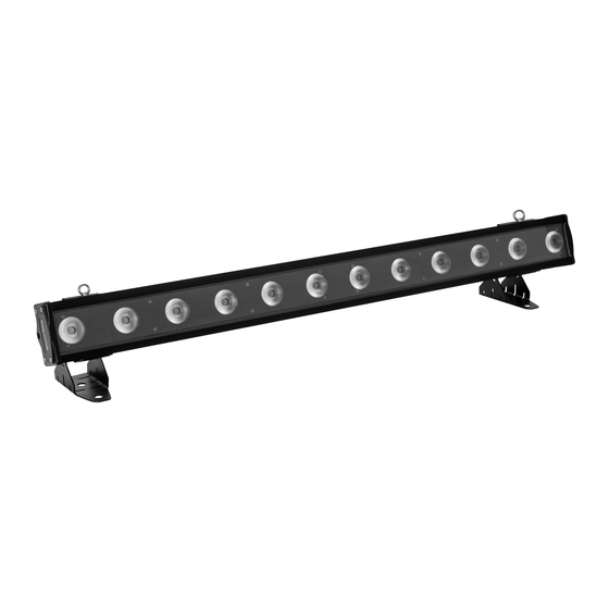
Seite 6: Gerätebeschreibung
GERÄTEBESCHREIBUNG (1) LED/Linse (2) Fangseilöse (3) Hängebügel/Standfuß (4) Control Board (5) Menu-Taste (6) Up-Taste (7) Display (8) Down-Taste (9) Enter-Taste (10) Spannungsversorgungseingang (11) DMX-Eingang PUSH (12) Spannungsversorgungsausgang (13) DMX-Ausgang 6/36 00126414, Version 1.0... -
Seite 7: Installation
INSTALLATION WARNUNG! Verletzungsgefahr durch Herabfallen Über Kopf installierte Geräte können beim Herabstürzen erhebliche Verletzungen verursachen! Stellen Sie sicher, dass das Gerät sicher installiert ist und nicht herunterfallen kann. Die Montage darf nur durch eine Fachkraft erfolgen, die mit den Gefahren und den einschlägigen Vorschriften hierfür vertraut ist. -
Seite 8: Dmx512-Ansteuerung
DMX512-ANSTEUERUNG Gerät 1 Gerät 2 Gerät 3 Startadresse 1 Startadresse 78 Startadresse 155 DMX-Controller Program Chase32 Step100 PUSH PUSH PUSH Für die Ansteuerung des Geräts per DMX512 ist eine Datenverbindung notwendig. Das Gerät verfügt dazu über 3-polige XLR-Anschlüsse. 1 Verbinden Sie den Ausgang Ihres Controllers mit dem DMX-Eingang DMX IN des Geräts über ein DMX- Kabel. -
Seite 9: Bedienung
BEDIENUNG Nach dem Anschluss ans Netz ist das Gerät betriebsbereit. Das Display zeigt die zuletzt eingestellte Betriebsart. Nehmen Sie nun die notwendigen Menüeinstellungen für die jeweilige Betriebsart mit den Bedientasten vor. Auch wenn Sie das Gerät vom Stromnetz trennen, bleiben alle Einstellungen gespeichert. Das Gerät kann entweder im Standalone-Modus über das Control Board oder im DMX-gesteuerten Modus über einen handelsüblichen DMX-Controller betrieben werden. -
Seite 10: Dmx-Betrieb
DMX-Betrieb Anzahl der DMX-Kanäle und DMX-Startadresse einstellen Für den Betrieb über einen Controller mit DMX512-Protokoll verfügt das Gerät über 77 Steuerkanäle. Es kann aber auch in einen Modus mit 6, 11, 24 oder 41 Kanälen umgeschaltet werden, wenn andere Funktionen benötigt werden. Damit das Gerät vom Controller angesteuert werden kann, muss außerdem die DMX-Startadresse eingestellt werden. - Seite 11 Farbe 6 Farbe 7 Farbe 8 Farbe 9 Farbe 10 Farbe 11 Farbe 12 Farbe 13 Farbe 14 Farbe 15 Farbe 16 Farbe 17 Farbe 18 Farbe 19 Farbe 20 Farbe 21 Farbe 22 Farbe 23 Farbe 24 Farbe 25 Farbe 26 Farbe 27 Farbe 28...
- Seite 12 Internes Programm 3 Internes Programm 4 Internes Programm 5 Internes Programm 6 Internes Programm 7 Internes Programm 8 Internes Programm 9 Internes Programm 10 Internes Programm 11 Internes Programm 12 Internes Programm 13 Internes Programm 14 Internes Programm 15 Internes Programm 16 Internes Programm 17 Internes Programm 18 Internes Programm 19...
- Seite 13 Weiß (LED 4, 5, 6) Weiß 0 - 100 % zunehmend Amber (LED 4, 5, 6) Amber 0 - 100 % zunehmend UV (LED 4, 5, 6) UV 0 - 100 % zunehmend Rot (LED 7, 8, 9) Rot 0 - 100 % zunehmend Grün (LED 7, 8, 9) Grün 0 - 100 % zunehmend Blau (LED 7, 8, 9)
- Seite 14 Blau (LED 1 + 7) Blau 0 - 100 % zunehmend Weiß (LED 1 + 7) Weiß 0 - 100 % zunehmend Amber (LED 1 + 7) Amber 0 - 100 % zunehmend UV (LED 1 + 7) UV 0 - 100 % zunehmend Rot (LED 2 + 8) Rot 0 - 100 % zunehmend Grün (LED 2 + 8)
- Seite 15 Farbe 14 Farbe 15 Farbe 16 Farbe 17 Farbe 18 Farbe 19 Farbe 20 Farbe 21 Farbe 22 Farbe 23 Farbe 24 Farbe 25 Farbe 26 Farbe 27 Farbe 28 Farbe 29 Farbe 30 Farbe 31 Farbe 32 Farbe 33 Farbe 34 Farbe 35 Farbe 36...
- Seite 16 Geschwindigkeit interne Programme Zunehmende Geschwindigkeit Modus/ Wert Eigenschaft Kanal 77 CH Dimmerintensität Allmähliche Einstellung der Dimmerintensität von 0 bis 100 % Strobe Keine Funktion Strobe-Effekt mit zunehmender Geschwindigkeit Rot (LED 1) Rot 0 - 100 % zunehmend Grün (LED 1) Grün 0 - 100 % zunehmend Blau (LED 1) Blau 0 - 100 % zunehmend...
- Seite 17 Farbe 7 Farbe 8 Farbe 9 Farbe 10 Farbe 11 Farbe 12 Farbe 13 Farbe 14 Farbe 15 Farbe 16 Farbe 17 Farbe 18 Farbe 19 Farbe 20 Farbe 21 Farbe 22 Farbe 23 Farbe 24 Farbe 25 Farbe 26 Farbe 27 Farbe 28 Farbe 29...
-
Seite 18: Reinigung Und Wartung
Internes Programm 14 Internes Programm 15 Internes Programm 16 Internes Programm 17 Internes Programm 18 Internes Programm 19 Musiksteuerung Geschwindigkeit interne Programme Zunehmende Geschwindigkeit REINIGUNG UND WARTUNG Das Gerät sollte äußerlich in regelmäßigen Abständen von Verunreinigungen wie Staub usw. gereinigt werden. -
Seite 19: Technische Daten
16 cm Gewicht: 7,4 kg Zubehör: EUROLITE TPC-10 Klammer, silber Best.-Nr. 59006856 EUROLITE Sicherungsseil A 4x1000mm bis 15kg silber Best.-Nr. 58010320 PSSO DMX Kabel IP65 3pol 1,5m sw Best.-Nr. 3022783A EUROLITE IP T-Con Netzkabel 3x1,5 1,5m Best.-Nr. 30235005 EUROLITE SB-12 Soft-Bag Best.-Nr. -
Seite 20: Introduction
USER MANUAL LED IP T-PIX 12 HCL Bar DANGER! Electric shock caused by short-circuit Be careful with your operations. With a dangerous voltage you can suffer a dangerous electric shock when touching the wires. Never open the housing. Please read these instructions carefully before using the product. They contain important information for the correct use of the product. -
Seite 21: Safety Instructions
SAFETY INSTRUCTIONS WARNING! Please read the safety warnings carefully and only use the product as described in this manual to avoid accidental injury or damage. Intended use • This product is designed to light indoor and outdoor areas and is IP65 rated. It can be mounted and operated in indoor and outdoor areas and is not dimmable. - Seite 22 Warning – risk of burns and fire • The admissible ambient temperature range (Ta) is -5 to +45°C. Do not operate the device outside of this temperature range. • The housing temperature (Tc) can be up to 60°C during use. Avoid contact by persons and materials. •...
-
Seite 23: Description Of The Device
DESCRIPTION OF THE DEVICE (1) LED/lens (2) Safety eyelet (3) Mounting bracket/foot (4) Control Board (5) Menu button (6) Up button (7) Display (8) Down button (9) Enter button (10) Power input (11) DMX input (12) Power output PUSH (13) DMX output 23/36 00126414, Version 1.0... -
Seite 24: Installation
INSTALLATION WARNING! Risk of injury caused by falling objects Devices in overhead installations may cause severe injuries when crashing down. Make sure that the device is installed securely and cannot fall down. The installation must be carried out by a specialist who is familiar with the hazards and the relevant regulations. The device may be placed on the floor or fastened to a truss or similar rigging structure. -
Seite 25: Dmx512 Control
DMX512 CONTROL Device 1 Device 2 Device 3 Start Address 1 Start Address 78 Start Address 155 DMX Controller Program Chase32 Step100 PUSH PUSH PUSH A DMX512 data link is required in order to control the device via DMX. The device provides 3-pin XLR connectors for DMX connection. -
Seite 26: Operation
OPERATION After connecting the device to the mains it is ready for operation. The display indicates the last operating mode. The operating modes can be selected by means of the display and the control buttons. All settings remain stored even if the device is disconnected from the mains. The device can be operated in stand-alone mode via the control board or in DMX-controlled mode via any commercial DMX controller. -
Seite 27: Dmx Operation
DMX operation Setting the number of DMX channels and the DMX starting address For operation with a controller with DMX512 protocol, the device is equipped with 77 control channels. However, it can also be switched to a mode with 6, 11, 24 or 41 channels if different functions are required. Tobe able to operate the device with a DMX controller, the DMX starting address must be set. - Seite 28 Color 7 Color 8 Color 9 Color 10 Color 11 Color 12 Color 13 Color 14 Color 15 Color 16 Color 17 Color 18 Color 19 Color 20 Color 21 Color 22 Color 23 Color 24 Color 25 Color 26 Color 27 Color 28 Color 29...
- Seite 29 Internal program 4 Internal program 5 Internal program 6 Internal program 7 Internal program 8 Internal program 9 Internal program 10 Internal program 11 Internal program 12 Internal program 13 Internal program 14 Internal program 15 Internal program 16 Internal program 17 Internal program 18 Internal program 19 Sound control...
- Seite 30 White 0 - 100 % increasing Amber (LED 4, 5, 6) Amber 0 - 100 % increasing UV (LED 4, 5, 6) UV 0 - 100 % increasing Red (LED 7, 8, 9) Red 0 - 100 % increasing Green (LED 7, 8, 9) Green 0 - 100 % increasing Blue (LED 7, 8, 9) Blue 0 - 100 % increasing...
- Seite 31 Blue 0 - 100 % increasing White (LED 1 + 7) White 0 - 100 % increasing Amber (LED 1 + 7) Amber 0 - 100 % increasing UV (LED 1 + 7) UV 0 - 100 % increasing Red (LED 2 + 8) Red 0 - 100 % increasing Green (LED 2 + 8) Green 0 - 100 % increasing...
- Seite 32 Color 16 Color 17 Color 18 Color 19 Color 20 Color 21 Color 22 Color 23 Color 24 Color 25 Color 26 Color 27 Color 28 Color 29 Color 30 Color 31 Color 32 Color 33 Color 34 Color 35 Color 36 Color 37 Color 38...
- Seite 33 Mode/ Value Feature Channel 77 CH Dimmer intensity Gradual adjustment of the dimmer intensity from 0 to 100 % Strobe No function Strobe-effect with increasing speed Red (LED 1) Red 0 - 100 % increasing Green (LED 1) Green 0 - 100 % increasing Blue (LED 1) Blue 0 - 100 % increasing White (LED 1)
- Seite 34 Color 13 Color 14 Color 15 Color 16 Color 17 Color 18 Color 19 Color 20 Color 21 Color 22 Color 23 Color 24 Color 25 Color 26 Color 27 Color 28 Color 29 Color 30 Color 31 Color 32 Color 33 Color 34 Color 35...
-
Seite 35: Cleaning And Maintenance
Speed internal programs Increasing speed CLEANING AND MAINTENANCE The outside of the device should be cleaned periodically to remove contaminants such as dust etc. The lenses, in particular, should be clean to ensure that light will be emitted at maximum brightness. Disconnect the device from power and allow it to cool before cleaning. -
Seite 36: Technical Specifications
No. 30130560 EUROLITE Omega Holder 36 No. 51786549 All information is subject to change without prior notice. © 17.10.2019 Eurolite is a brand of Steinigke Showtechnic GmbH Andreas-Bauer-Str. 5 97297 Waldbüttelbrunn Germany D00126414 Version 1.0 Publ. 17/10/2019 36/36 00126414, Version 1.0...