Herunterladen Inhalt Inhalt Diese Seite drucken

Werbung

Verfügbare Sprachen
  • DE

Verfügbare Sprachen

  • DEUTSCH, seite 26
SDI Output Board
取扱説明書 
Operating Instructions
Mode d'emploi
Bedienungsanleitung
Istruzioni per l'uso
######
####
お買い上げいただきありがとうございます。
電気製品は、安全のための注意事項を守らないと、
火災や人身事故になることがあります。
ご使用にあたっては、カメラコントロールユニットに付属の取
扱説明書の「安全のために」と 「
みください。お読みになったあとは、いつでも見られるところ
に必ず保管してください。
本基板の取り付けは必ずお買い上げ店またはソニーのサービス
窓口にご依頼ください。
DXBK-701
© 1998 by Sony Corporation
2
ページ
Page 11
Page 18
Seite 26
Pagina 34
警告」 、 「
3-866-203-02(1)
JP
GB
FR
DE
IT
CS
注意」をよくお読

Werbung

Inhaltsverzeichnis
loading

Inhaltszusammenfassung für Sony DXBK-701

  • Seite 1 Operating Instructions Page 11 Mode d’emploi Page 18 Bedienungsanleitung Seite 26 Istruzioni per l’uso Pagina 34 ######   #### お買い上げいただきありがとうございます。 電気製品は、安全のための注意事項を守らないと、 火災や人身事故になることがあります。 • ご使用にあたっては、カメラコントロールユニットに付属の取 扱説明書の「安全のために」と 「 警告」 、 「 注意」をよくお読 みください。お読みになったあとは、いつでも見られるところ に必ず保管してください。 • 本基板の取り付けは必ずお買い上げ店またはソニーのサービス 窓口にご依頼ください。 DXBK-701 © 1998 by Sony Corporation...
  • Seite 2 日本語 安全のために ソニー製品は安全に充分配慮して設計されています。 しかし、 警告表示の意味 電気製品は、 まちがった使いかたをする と、 火災や感電などに 取扱説明書および製品 よ り死亡や大けがなど人身事故につながる こ とがあ り 、 危険で では、次のような表示 す。事故を防ぐために次のこ とを必ずお守り く ださい。 をしています。表示の 内容をよく理解してか 安全のための注意事項を守る ら本文をお読みくださ 3 ページの注意事項をよく お読みく ださい。 い。 定期点検をする 長期間、 安全にお使いいただく ために、 定期点検をする こ とを この表示の注意事項を おすすめします。 点検の内容や費用については、 お買い上げ 守らないと、感電やそ...
  • Seite 3 取り付けと調整 ..............オー ト レベル調整 ................9 仕様 ..................けが 下記の注意を守らないと、 をしたり周辺の物品に 注意 損害 を与えることがあります。 日 本 語 CCU-TX7 31000 のシリアルナンバー 以前に取り付 けない DXBK-701は、 シリ アルナンバー31001 以降の CCU-TX7に取り付ける別 売り基板です。 シリ アルナンバー31000 以前のCCU-TX7に取り付ける場 合は、別途放熱を向上させる改造が必要です。改造しないで取り付ける と発熱によるやけどの原因となる こ とがあ り ますので、 お買い上げ店また はソニーのサービス窓口にご依頼く ださい。...
  • Seite 4 概要 SDIアウ トプッ トボー ド DXBK-701は、ソニーカメラコン ト ロールユニッ ト CCU-TX7 のためのオプシ ョ ン基板です。 本基板をCCU-TX7に取り付ける こ とによ り 、 SDIデジタル信号の出力が可 能になり ます。 ご注意 本基板はシリ アルナンバー31001 以降のCCU-TX7に取り付ける こ とがで きます 。 取り付ける と き発熱によるやけどなどの原因になる こ とがあ り ますので、 必 ずお買い上げ店またはソニーのサービス窓口にご相談く ださい。 ..................................
  • Seite 5 各部の名称と働き SDI-44 ALARM インジケーター ALARM 出力端子 AUTO LEVEL インジケーター AUTO LEVEL (BARS) AUTO LEVEL スイッチ SDI POWER SDI POWER スイッチ ALARM( AUTO LEVEL( アラーム インジケーター オートレベル SDI出力されていないと きに赤く 点灯します。 スイッチ 出力をカラーバーにしてこのスイ ッチを押す 出力端子 と、自動的にビデオレベルを調整できます。 CCU のケーブル (2 本)を接続します。 SDI POWER( パワー...
  • Seite 6 取り付けと調整 取り付けを行う前に、 CCU-TX7 の電源を切ってく ださい。 DXBK-701基板 (SDI-44)上のスイ ッチが以下のよ う になっている こ と を確認する。 FREE LOCK:LOCK ADJ OPE:OPE AUDIO MODE:通常は2CH、 接続した機器が2CHモー ドに対応し ていないときは 4CHにする。 (チャ ンネル3、 4に音声は送れません。 ) FREE LOCK FREE LOCK ADJ OPE ADJ OPE 4ch 2ch AUDIO MODE CCU-TX7 の前面パネル右側のネジ2 本をゆるめて前面パネルを開...
  • Seite 7 基板を途中まで基板スロ ッ ト に入れる。 CCU-TX7の電源部に仮止めされている2本のケーブルをクラ ンパー から取り外し、 それぞれ基板のSDI 出力端子(2か所)に取り付ける。 どち らのケーブルをどち らの端子に取り付けてもかまいません。 出力端子 クランパー ケーブル (続く )
  • Seite 8 取り付けと調整 基板を奥まで差し込み、手順 2 で取り外したネジを使って基板抜け 止め板をネジ止めする。 基板抜け止め板 SDI POWERスイ ッチをONにする。 (5 ページ参照。 ) CCU-TX7の電源を入れ、 オー ト レベル調整を行う 。 (9ページ参照。 ) CCU-TX7 の前面パネルを閉じて、 ネジを締める。...
  • Seite 9 オートレベル調整 オー ト レベル調整は、 ビデオレベルを適正な値にするために必要な操作で す。 「取り付けと調整」 の手順 6 (前ページ)でオー ト レベル調整を行います。 CCU-TX7、 CA-TX7 およびカメ ラの電源を入れる。 RCP-TX7または COU-TX7 で「BARS」 を選択する。 モニターまたはビューフ ァイ ンダーにカラーバーが表示されます。 ペン先などで本基板の AUTO LEVELスイ ッチを押す。 数秒たってAUTO LEVELイ ンジケーターが緑色に点灯すれば、 オー ト レベル調整は完了です。 ご注意 • イ ンジケーターが赤色に点灯した場合は、 基板上のスイ ッチの設定を確 認してく ださい (6 ページの手順 1 参照)。 また、 イ ンジケーターが点滅し た場合は、カラーバーが表示されているか確認してく...
  • Seite 10 仕様 消費電力 4.5W 動作温度 5℃∼40 ℃ 質量 330 g 外形寸法 17×148×277mm (幅 / 高さ/ 奥行き、突起部を除く ) 出力信号 SDI 出力端子 SDIフォーマッ ト (270Mbps) SMPTE 259M...
  • Seite 11: Inhaltsverzeichnis

    Fitting and Adjustment ..........13 Auto Level Adjustment..........16 Specifications ..............17 Overview The DXBK-701 SDI Output Board is an option board for the Sony CCU-TX7/TX7P Camera Control Unit. When this board is fitted in a CCU-TX7/TX7P, it provides an SDI digital signal output.
  • Seite 12: Location And Function Of Parts

    Location and Function of Parts SDI-44 1 ALARM indicator ALARM 2 SDI output connectors 3 AUTO LEVEL indicator AUTO LEVEL (BARS) 4 AUTO LEVEL switch SDI POWER 5 SDI POWER switch 1 ALARM indicator 4 AUTO LEVEL switch This lights red when the SDI signal is With the output set to color bars, press not being output.
  • Seite 13: Fitting And Adjustment

    Fitting and Adjustment Power off the CCU-TX7/TX7P before fitting the board. Check that the switches on the DXBK-701 board (SDI-44) are set as follows. FREE LOCK: LOCK ADJ OPE: OPE AUDIO MODE: normally 2CH; 4CH if the connected device does not support 2CH mode. (No audio output is provided on channels 3 and 4.)
  • Seite 14 Fitting and Adjustment Insert the board partly into the slot. Remove the two cables temporarily fixed to the CCU-TX7/ TX7P power supply unit from the clamp, and connect to the two SDI output connectors on the board. It does not matter which cable is connected to which connector.
  • Seite 15 Push the board fully in, and refasten the board retainer, using the two screws removed in step 2. Board retainer Set the SDI POWER switch to ON. (See page 12.) Power on the CCU-TX7/TX7P, and carry out auto level adjustment. (See page 16.) Close the front panel of the CCU-TX7/TX7P, and fasten the screws.
  • Seite 16: Auto Level Adjustment

    Fitting and Adjustment Auto Level Adjustment The auto level adjustment is necessary to ensure that the video levels are appropriate. Carry out auto level adjustment in step 6 (page 15) of the procedure under “Fitting and Adjustment”. Power on the CCU-TX7/TX7P, CA-TX7/TX7P, and camera.
  • Seite 17: Specifications

    Specifications Power consumption 4.5 W Operating temperature 5°C to 40°C (41°F to 104°F) Mass 330 g (11 oz) 17 × 148 × 277 mm ( × 5 × 11 Dimensions inches) (w/h/d, excluding projections) Output signal SDI output connectors SDI format (270 Mbps) SMPTE 259M (CCU-TX7)/ CCIR 656-III (CCU-TX7P)
  • Seite 18 Français Pour les clients européens Ce produit portant la marque CE est conforme à la fois à la Directive sur la compatibilité électromagnétique (EMC) (89/336/CEE) émises par la Commission de la Communauté européenne. La conformité à cette directives implique la conformité aux normes européennes suivantes: •...
  • Seite 19: Aperçu

    Aperçu La carte de sortie SDI DXBK-701 est une carte optionnelle prévue pour le contrôleur de caméra CCU-TX7/TX7P Sony. Insérée, elle permet la sortie de signaux numériques SDI. Remarque Cette carte peut être insérée dans les CCU-TX7 à numéro de série 11001 ou plus ou les CCU-TX7P à...
  • Seite 20: Localisation Et Fonction Des Pièces

    Localisation et fonction des pièces SDI-44 1 Témoin ALARM ALARM 2 Connecteurs de sortie SDI 3 Témoin AUTO LEVEL AUTO LEVEL (BARS) 4 Commutateur AUTO LEVEL SDI POWER 5 Interrupteur SDI POWER 1 Témoin d’alarme (ALARM) 4 Commutateur de niveau S’allume en rouge quand le signal automatique (barres) (AUTO SDI n’est pas sorti.
  • Seite 21: Installation Et Ajustement

    Installation et ajustement Mettez le CCU-TX7/TX7P hors tension avant d’insérer la carte. Vérifiez que les commutateurs de la carte DXBK-701 (SDI-44) sont réglés comme suit: FREE LOCK: LOCK ADJ OPE: OPE AUDIO MODE: normalement 2CH; 4CH si l’appareil raccordé n’assiste pas le mode 2CH. (Aucune sortie audio n’est fournie aux canaux 3 et 4.)
  • Seite 22 Installation et ajustement Insérez partiellement la carte dans la fente. Retirez temporairement les deux câbles insérés dans la section d’alimentation du CCU-TX7/TX7P du serre-câbles pour les raccorder aux deux connecteurs de sortie SDI de la carte. Ces câbles peuvent se raccorder indifféremment aux deux connecteurs.
  • Seite 23 Enfoncez la carte à fond, et remettez la retenue de carte en place avec les deux vis retirées à l’étape 2. Retenue de carte Réglez l’interrupteur SDI POWER à ON. (Voir page 20.) Mettez le CCU-TX7/TX7P sous tension, et effectuez l’ajustement automatique du niveau.
  • Seite 24: Ajustement Automatique Du Niveau

    Installation et ajustement Ajustement automatique du niveau L’ajustement automatique du niveau est nécessaire pour assurer que les niveaux vidéo sont corrects. Effectuez l’ajustement automatique du niveau de l’étape 6 (page 23) de la procédure “Installation et ajustement”. Mettez le CCU-TX7/TX7P, le CA-TX7/TX7P et la caméra sous tension.
  • Seite 25: Spécifications

    Spécifications Consommation 4,5 W Température de fonctionnement 5 à 40°C (41 à 104°F) Poids 330 g (11 onces) 17 × 148 × 277 mm ( × 5 × 11 Dimensions pouces) (l/h/p, saillies exclues) Signal de sortie Connecteurs de sortie SDI Format SDI (270 Mbps) SMPTE 259M (CCU-TX7)/ CCIR 656-III (CCU-TX7P)
  • Seite 26 Deutsch Für Kunden in Europa Dieses Produkt besitzt die CE-Kennzeichnung und erfüllt die EMV-Direktive (89/336/EEC) der EG-Kommission. Die Erfüllung dieser Direktiven bedeutek Konformität für die folgenden Europäischen Normen: • EN55103-1: Elektromagnetische Interferenz (Emission) • EN55103-2: Elektromagnetische Empfindlichkeit (Immunität) Dieses Produkt ist für den Einsatz unter folgenden elektromagnetischen Bedingungen ausgelegt: E1 (Wohnbereich), E2 (kommerzieller und in beschränktem Maße industrieller Bereich), E3...
  • Seite 27: Überblick

    Verbrennungen verursachen. Überlassen Sie die Installationsarbeiten nur einem Sony-Fachhändler........................... 1) Die Installation dieser Karte in eine CCU-TX7P mit einer Seriennummer unter 41000 erfordert eine Modifikation der Kamera- Steuereinheit. Wenden Sie sich in einem solchen Fall bitte an den Sony- Fachhändler.
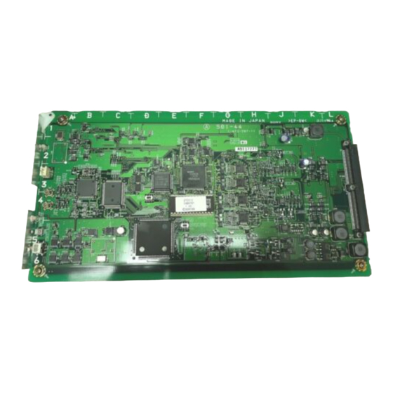
  • Seite 28: Lage Und Funktion Der Teile

    Lage und Funktion der Teile SDI-44 1 ALARM-Anzeige ALARM 2 SDI-Ausgänge 3 AUTO LEVEL-Anzeige AUTO LEVEL (BARS) 4 AUTO LEVEL-Schalter SDI POWER 5 SDI POWER-Schalter 1 ALARM-Anzeige 4 AUTO LEVEL-Schalter Leuchtet rot, wenn kein SDI-Signal Diesen Schalter bei auf Farbbalken ausgegeben wird.
  • Seite 29: Installation

    Installation Schalten Sie die CCU-TX7P aus, bevor Sie mit der Installation beginnen. Sorgen Sie dafür, daß die Schalter auf der Leiterplatte DXBK-701 (SDI-44) wie folgt eingestellt sind: FREE LOCK: LOCK ADJ OPE: OPE AUDIO MODE: normalerweise auf 2CH; falls Anschluß...
  • Seite 30 Installation Schieben Sie die Karte provisorisch in den Schlitz ein. Befreien Sie die zwei Kabel, die provisorisch am Netzteil der CCU-TX7P befestigt sind, vom Kabelhalter, und schließen Sie sie an die zwei SDI-Ausgänge an der Karte an. Es spielt dabei keine Rolle, welches Kabel an welchen Ausgang angeschlossen wird.
  • Seite 31 Drücken Sie die Karte nun vollständig ein, und schrauben Sie den Leiterplattenhalter wieder mit den in Schritt 2 gelösten Schrauben an. Leiterplattenhalter Stellen Sie den SDI POWER-Schalter auf ON. (Siehe Seite 28.) Schalten Sie die CCU-TX7P ein, und führen Sie eine automatische Pegelaussteuerung aus.
  • Seite 32: Automatische Pegelaussteuerung

    Installation Automatische Pegelaussteuerung Die automatische Pegelaussteuerung ist erforderlich, um korrekte Videopegel zu gewährleisten. Nehmen Sie diese Aussteuerung in Schritt 6 (Seite 31) unter „Installation“ vor. Schalten Sie die CCU-TX7P, CA-TX7P und die Kamera ein. Wählen Sie „BARS“ an der RCP-TX7 oder COU-TX7P. Im Monitor oder Sucher werden daraufhin Farbbalken angezeigt.
  • Seite 33: Technische Daten

    Technische Daten Leistungsaufnahme 4,5 W 5 °C bis 40 °C Betriebstemperatur Gewicht 330 g 17 × 148 × 277 mm Abmessungen (B/H/T) Ausgangssignal SDI-Ausgänge SDI-Format (270 Mbps) CCIR 656-III...
  • Seite 34: Descrizione

    Regolazione automatica del livello ....... 39 Caratteristiche tecniche ..........40 Descrizione La scheda di uscita segnali SDI DXBK-701 è una scheda opzionale per l’unità di controllo videocamera CCU-TX7P. Quando questa scheda è installata in una CCU-TX7P fornisce un’uscita di segnali SDI digitali.
  • Seite 35: Posizione E Funzione Delle Parti

    Posizione e funzione delle parti SDI-44 1 Indicatore ALARM ALARM 2 Connettori di uscita segnali SDI 3 Indicatore AUTO LEVEL AUTO LEVEL (BARS) 4 Interruttore AUTO LEVEL SDI POWER 5 Interruttore SDI POWER 1 Indicatore di avvertenza 4 Interruttore di regolazione (ALARM) automatica del livello (AUTO Questo indicatore si illumina in rosso...
  • Seite 36: Installazione E Regolazione

    Installazione e regolazione Spegnere la CCU-TX7P prima di installare la scheda. Controllare che gli interruttori sulla scheda DXBK-701 (SDI-44) siano regolati come descritto di seguito. FREE LOCK: LOCK ADJ OPE: OPE AUDIO MODE: Normalmente 2CH; 4CH se il dispositivo collegato non supporta il modo 2CH. (Nessuna uscita audio viene fornita sui canali 3 e 4.)
  • Seite 37 Inserire la scheda parzialmente nella fessura. Rimuovere i due cavi temporaneamente fissati all’unità di alimentazione della CCU-TX7P dal morsetto, e collegarli ai due connettori di uscita segnali SDI sulla scheda. I due cavi possono essere collegati indifferentemente ai due connettori. Connettori di uscita segnali SDI Morsetto Cavi...
  • Seite 38 Installazione e regolazione Spingere la scheda fino in fondo, e rimettere a posto il fermo della scheda, fissandolo con le due viti rimosse al punto 2. Fermo della scheda Regolare l’interruttore SDI POWER su ON. (Vedere pagina 35.) Accendere la CCU-TX7P, ed eseguire la regolazione automatica del livello.
  • Seite 39: Regolazione Automatica Del Livello

    Regolazione automatica del livello La regolazione automatica del livello è necessaria per assicurare che i livelli video siano appropriati. Eseguire la regolazione automatica del livello al punto 6 (pagina 38) del procedimento descritto in “Installazione e regolazione”. Accendere la CCU-TX7P, il CA-TX7P e la videocamera. Sull’RCP-TX7 o sulla COU-TX7P selezionare “BARS”.
  • Seite 40: Caratteristiche Tecniche

    Caratteristiche tecniche Consumo 4,5 W Temperatura di impiego Da 5°C a 40°C Massa 330 g 17 × 148 × 277 mm (l/a/p, escluse le Dimensioni parti sporgenti) Segnale di uscita Connettori di uscita segnali SDI Formato SDI (270 Mbps) CCIR 656-III...
  • Seite 41 Sony Corporation Printed in Japan...

Inhaltsverzeichnis