Comelit Simplebus 2 Technisches Handbuch
IT
EN
MANUALE
TECHNICAL
TECNICO
MANUAL
ATTENZIONE - WARNING - AVERTISSEMENT- WAARSCHUWING- ACHTUNG - AVISO - ADVERTENCIAS
UTILIZZO MODULI
USE OF
SIMPLEBUS
UTILISATION DES MODULES
GEBRUIK VAN
SIMPLEBUS
VERWENDUNG VON SIMPLEBUS-MODULEN IN VANDALCOM TASTATUREN, ROMA, AV4 E N
USO MODULOS
USO DOS MÓDULOS
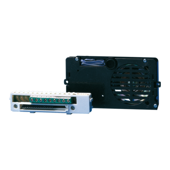
Programmazione pulsanti con gruppo audio Art. 1602 o audio-video Art. 4660, 4660C.
IT
Pushbutton programming with audio unit Art. 1602 or audio-video Art. 4660, 4660C.
EN
Programmation des boutons avec groupe audio Art. 1602 ou audio-vidéo Art. 4660, 4660C.
FR
NL
Programmering drukknoppen met audiomodule Art. 1602 of audio-videomodule Art. 4660, 4660C.
Tastenprogrammierung mit A-Einheit Art. 1602 oder A/V-Einheit 4660, 4660C.
DE
Programación de los pulsadores con grupo audio Art. 1602 o audio y vídeo Art. 4660 o 4660C.
ES
Programação dos botões com grupo áudio Art. 1602 ou áudio-vídeo Art. 4660, 4660C.
PT
1A
1. Sulla morsettiera del modulo Art. 1602, 4660, 4660C collegare l'alimentazione su ~~ ,
IT
spostare l'interruttore in posizione di programmazione (quadrato rosso) (vedi figura 1A).
Connettere la morsettiera al modulo Art. 1602, 4660, 4660C.
2. Impostare il Dip switch (figura 2) posto sul retro del modulo audio o audio-video con lo stesso
codice assegnato al citofono o al monitor, secondo la corrispondenza descritta nella tabella
di programmazione (vedi manuale o foglio tecnico riferito al posto esterno e al miscelatore).
3. Premere il pulsante che si desidera associare alla chiamata del citofono. L'avvenuta
programmazione viene segnalata con un tono di conferma.
4. Al termine della programmazione riposizionare l'interruttore in posizione di standby
(quadrato bianco) (figura 1B).
EN
1. On the terminal board of module Art. 1602, 4660, 4660C connect the power supply to ~~,
set the switch to programming position (red square) (figure 1A). Connect the terminal board
to module Art. 1602, 4660, 4660C.
2. Set the Dip switch (figure 2) located on the back of the audio or audio-video module with
the same code assigned to the interphone or monitor, according to the matching described
in the programming table (see technical manual or sheets for the external unit and mixer).
3. Press the pushbutton to be associated with the interphone call. A confirmation tone signals
that programming has taken place.
4. After programming, set the switch to standby (white square) (see figure 1B).
FR
1. Sur le bornier du module Art. 1602, 4660, 4660C, brancher l'alimentation sur ~~ , déplacer
le commutateur en position de programmation (carré rouge) (voir fig. 1A). Brancher le
bornier au module Art. 1602, 4660, 4660C.
2. Programmer le dip-switch (figure 2) placé sur le dos du module audio ou audio-vidéo avec
le même code attribué au combiné parlophonique ou au moniteur selon la correspondance
décrite dans le tableau de programmation (voir manuels ou feuille technique se référant à
la plaque de rue et au mélangeur).
3. Appuyer sur le bouton que l'on désire associer à l'appel du combiné parlophonique. La
réalisation de la programmation est signalée par un bip de confirmation.
4. À la fin de la programmation, remettre le commutateur en position de standby (carré
blanc) (voir fig. 1B).
NL
1. Sluit de voeding aan op de klemmen ~ ~ van de module 1602, 4660, 4660C en zet de
schakelaar in de programmeerstand (rood) (zie afbeelding 1A). Verbind het aansluitblok
met de modulen art. 1602, 4660, 4660C.
2. Zet de dipswitch (afbeelding 2) aan de achterzijde van de audio- of audio-videomodule op
dezelfde code als op de huistelefoon of monitor ingesteld is aan de hand van de
programmeertabel (zie de handleiding of het technische blad van het entreepaneel en van
de mixer).
FR
NL
MANUEL
TECHNISCHE
TECHNIQUE
HANDLEIDING
SIMPLEBUS
IN PULSANTIERE VANDALCOM, ROMA, AV4 E N
MODULES IN VANDALCOM, ROMA, AV4 AND N SERIES ENTRANCE PANELS
SIMPLEBUS
DANS DES PLAQUES DE RUE VANDALCOM, ROMA, AV4 ET N
MODULES IN VANDALCOM, ROMA, AV4 EN N-SERIES ENTREEPANELEN
SIMPLEBUS
EN PLACAS DE CALLE VANDALCOM, ROMA, AV4 Y N
SIMPLEBUS
NAS BOTONEIRAS VANDALCOM, ROMA, AV4 E N
1B
DE
TECHNISCHES
HANDBUCH
2
3. Druk nu op de drukknop die op deze code moet worden geprogrammeerd. Een
bevestigingstoon geeft aan dat de knop is geprogrammeerd.
4. Zet de schakelaar na de programmering terug in de standby-stand (wit) (zie
afbeelding 1B).
DE
1. Auf der Klemmenleiste des Moduls Art. 1602, 4660, 4660C das Netzteil an ~~ anschließen,
den Schalter auf Programmierung (rotes Quadrat) setzen (siehe Abb. 1A). Die
Klemmenleiste mit dem Modul Art. 1602, 4660, 4660C verbinden.
2. Den Dip Switch (Abb. 2) an der Rückseite des A- oder A/V-Moduls auf denselben Code
einstellen wie den der Innensprechstelle oder des Monitors entsprechend der
Beschreibung in der Programmiertabelle (siehe Handbuch oder technisches Datenblatt
betreffs der Außenstelle und des Mischers).
3. Die Taste drücken, der der Ruf an der Innenstelle zugeordnet werden soll. Die erfolgte
Programmierung wird durch einen Ton bestätigt.
4. Zum Abschluss der Programmierung den Schalter auf Stand-by zurücksetzen
(weißes Quadrat) ( Abb. 1B).
ES
1. En la regleta de conexiones del módulo (art. 1602, 4660 o 4660C), conectar la alimentación a
~~ y desplazar el interruptor a la posición de programación, correspondiente al cuadrado rojo
(véase la figura 1A). Conectar la regleta de conexiones al módulo (art. 1602, 4660 o 4660C).
2. Configurar los interruptores DIP (figura 2), ubicados en la parte trasera del módulo audio o
del módulo audio y vídeo, con el mismo código asignado al teléfono o al monitor según la
correspondencia descrita en la tabla de programación (véanse el manual o la hoja técnica
sobre la unidad externa y sobre el mezclador).
3. Presionar el pulsador que se desea asociar a la llamada del teléfono. La programación está
señalada con un tono de confirmación.
4. Al final de la programación, desplazar el interruptor a la posición de standby,
correspondiente al cuadrado blanco (figura 1B).
PT
1. No quadro de bornes do módulo Art. 1602, 4660, 4660C ligar a alimentação em ~~ ,
colocar o interruptor na posição de programação (quadrado vermelho) (ver figura 1A). Ligar
o quadro de bornes ao módulo Art. 1602, 4660, 4660C.
2. Configurar o Dip switch (figura 2) colocado na parte traseira do módulo áudio ou áudio-
vídeo com o mesmo código atribuído ao intercomunicador ou monitor, de acordo com a
correspondência descrita na tabela de programação (consultar o manual ou a ficha técnica
que se encontra no posto externo e no dispositivo misturador).
3. Apertar o botão que se pretende associar à chamada do intercomunicador. A programação
efectuada é sinalizada com um sinal sonoro de confirmação.
4. No final da programação voltar a colocar o interruptor na posição standby (quadrado
branco) (figura 1B).
ES
PT
MANUAL
MANUAL
TÉCNICO
TÉCNICO
1

Verwandte Anleitungen für Comelit Simplebus 2


Inhaltszusammenfassung für Comelit Simplebus 2
- Seite 1 MANUALE TECHNICAL MANUEL TECHNISCHE TECHNISCHES MANUAL MANUAL TECNICO MANUAL TECHNIQUE HANDLEIDING HANDBUCH TÉCNICO TÉCNICO ATTENZIONE - WARNING - AVERTISSEMENT- WAARSCHUWING- ACHTUNG - AVISO - ADVERTENCIAS UTILIZZO MODULI SIMPLEBUS IN PULSANTIERE VANDALCOM, ROMA, AV4 E N USE OF SIMPLEBUS MODULES IN VANDALCOM, ROMA, AV4 AND N SERIES ENTRANCE PANELS UTILISATION DES MODULES SIMPLEBUS DANS DES PLAQUES DE RUE VANDALCOM, ROMA, AV4 ET N...
- Seite 2 Operazioni per usare i pulsanti di serie del frutto 1602 e 4660 in impianti Simplebus. Operations for using the pushbuttons of the audio speaker unit 1602 and 4660 in Simplebus systems. Marche à suivre pour monter les boutons de série du module 1602 et 4660 dans des installations Simplebus. Werkzaamheden voor het aansluiten van drukknoppen op de audio luidsprekerunit 1602 en 4660 in Simplebus systemen.
- Seite 3 Fig. 4b Fig. 3c Fig. 4c Fig. 5c Operazione da effettuare solo se non sono presenti moduli pulsan- ti Art. 3063/A o 3063B. Per utilizzare più di 2 pulsanti, montare esclusivamente i moduli 3063B o 3063/A. Operation to be carried out only if pushbutton modules Art. 3063/A or 3063B are not present.
- Seite 4 SB2/ABS Impianto audio-video Simplebus con pulsantiera monoplacca e modulo Art. 3063B. Simplebus audio-video system with single-plate entrance panel and module Art. 3063B. Installation audio-vidéo Simplebus avec plaque de rue et module Art. 3063B. Simplebus audio-videosysteem met entreepaneel uit één stuk en module Art. 3063B. Simplebus Audio-/Videoanlage mit Tastatur mit durchgehender Frontblende und Modul Art.
- Seite 5 ATTENZIONE! LA DOCUMENTAZIONE SEGUENTE È DA UTILIZZARE ESCLUSIVAMENTE IN CASO DI UTILIZZO DEI MODULI ART. 3063/A E 3064/A ATTENTION! USE THE FOLLOWING DOCUMENTATION ONLY WHEN USING MODULES ART. 3063/A AND 3064/A ATTENTION ! LA DOCUMENTATION SUIVANTE EST EXCLUSIVEMENT UTILISÉE EN CAS D'EMPLOI DES MODULES ART.
- Seite 6 SB2/AAU Impianto audio-video Simplebus con pulsantiera Vandalcom e 4660, 4660C o 1602 e modulo 3064/A. Simplebus audio-video system with Vandalcom entrance panel and 4660, 4660C or 1602 and module 3064/A. Installation audio-vidéo Simplebus avec plaque de rue Vandalcom et 4660, 4660C ou 1602 et module Art. 3064/A. Simplebus audio-videosysteem met Vandalcom-entreepaneel en 4660, 4660C of 1602 en module 3064/A.