Inhaltsverzeichnis
Werbung
Verfügbare Sprachen
Verfügbare Sprachen
Werbung
Kapitel
Inhaltsverzeichnis

Verwandte Anleitungen für Electrolux IK225SR: IK225SL: IK227SR: IK227SL: IK293SR: IK293SL


Inhaltszusammenfassung für Electrolux IK225SR: IK225SL: IK227SR: IK227SL: IK293SR: IK293SL
- Seite 1 IK225SR IK225SL IK227SR IK227SL IK293SR IK293SL...
-
Seite 2: Inhaltsverzeichnis
Inhalt Entsorgungshinweis Das Gerät enthält wertvolle Materialien und ist einer Gerätebeschreibung ..............2 vom unsortierten Siedlungsabfall getrennten Erfas- Entsorgungshinweis ..............2 sung zuzuführen. Die Entsorgung von ausgedienten Sicherheits- und Warnhinweise..........3 Geräten muss fach- und sachgerecht nach den örtlich Einsatzbereich des Gerätes .............3 geltenden Vorschriften und Gesetzen erfolgen. -
Seite 3: Sicherheits- Und Warnhinweise
Sicherheits- und Warnhinweise • Um Personen- und Sachschäden zu vermeiden, • Verzehren Sie keine überlagerten Lebensmittel, sie können zu einer Lebensmittelvergiftung füh- sollte das Gerät von zwei Personen ausgepackt und aufgestellt werden. ren. • Lagern Sie keine explosiven Stoffe oder Sprüh- •... -
Seite 4: Klimaklasse
Klimaklasse Bedien- und Kontrollelemente Die Klimaklasse gibt an, bei welcher Das Elektronik-Bedienfeld hat die "Kapazitive Tastentechno- Raumtemperatur das Gerät betrieben logie". werden darf, um die volle Kälteleistung Jede Funktion kann durch Berührung des jeweiligen Symbols zu erreichen. aktiviert werden. Die Klimaklasse ist am Typenschild auf- gedruckt. -
Seite 5: Temperatur Einstellen
Temperatur einstellen Kindersicherung Mit der Kindersicherung können Sie das Gerät vor ungewolltem Ausschalten sichern. Temperatur erhöhen/wärmer Einstelltaste drücken. Kindersicherung aktivieren 5 Sek. drücken. >> Anzeige = Temperatur senken/kälter Einstelltaste drücken. Anzeige = - Beim ersten Tastendruck beginnt die Anzeige zu blinken. - Durch weiteres Drücken die Temperatureinstellung verändern. -
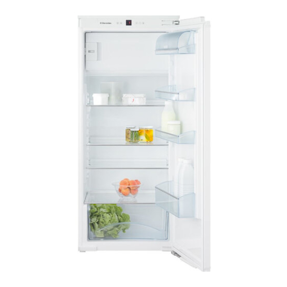
Seite 6: Ausstattung
Ausstattung Die Abstellflächen sind je nach Kühlguthöhe versetzbar. Glasplatte anheben, Aussparung über Auflage ziehen und höher oder tiefer einsetzen. Rollenschienen zum Reinigen entnehmen Innenbeleuchtung Geteilte Abstellfläche Wenn Sie Platz für hohe Ge- Die Innenbeleuchtung schaltet sich fäße benötigen, dann einfach immer ein, wenn die Tür des Gerätes die vordere halbe Glasplatte geöffnet wird. -
Seite 7: Kühlen
Kühlen Gefrierfach Im Gefrierfach können Sie bei einer Temperatur von -18 °C und Einordnungsbeispiel tiefer Tiefkühlkost und Gefriergut mehrere Monate lagern, Eis- Butter, Käse würfel bereiten und frische Lebensmittel einfrieren. Eier, Dosen, Tuben Die Lufttemperatur im Fach, gemessen mit Thermometer oder anderen Messgeräten, kann schwanken. -
Seite 8: Abtauen
Abtauen Störung Der Kühlraum taut automatisch ab. • Im Anzeigedisplay erscheint F0, F1, F2, F3, F4, F5, F6, F7, F8 oder F9. Gefrierfach – Am Gerät liegt ein Fehler vor. Den Kundendienst kontaktieren. An den Wänden des Gefrierraums bildet sich nach längerer Betriebszeit eine Reif- bzw. -
Seite 9: Mitgelieferte Zubehörteile
Mitgelieferte Zubehörteile 2 Stk. Abdeckungen für Öffnungen am Innenbehälter im Bereich des Gefrierfaches. Abdeckprofil (deckt den Spalt zwischen Oberseite des Gerätes und Nische ab). Diese werden benötigt, wenn der Türanschlag des Gerätes gewechselt wird. Abdeckungen Montage links oben bei Türanschlag rechts. 2 Stk. -
Seite 10: Türanschlag Wechseln
Türanschlag wechseln Achtung Der Wechsel des Türanschlags sollte nur von ausgebildetem Die Tür muss nun von einer Person festgehalten werden. Fachpersonal durchgeführt werden. Für den Umbau sind zwei Personen erforderlich. 5. Schrauben herausdrehen. Tür abnehmen. 1. Abdeckung abnehmen. 2. Schließdämpfer nach unten ziehen. Der Schließdämpfer zieht sich darauf- hin zusammen. -
Seite 11: Gefrierfachtür Umsetzen
12. Schließhaken umsetzen. 13. Die freien Öffnungen mit den Abdeckungen (im Beipackbeutel enthalten) verschließen. 8. Haltewinkel herausziehen und auf die Gegenseite umsetzen. 14. Halterung umsetzen. 15. Fachtür 180 ° wenden. 9. Oberen Befestigungswinkel anschrauben. Hinweis Schrauben eindrehen, den Winkel ganz nach links schieben, dann Schrauben festziehen. - Seite 12 22. Schließdämpfer anschrauben. 19. Scharniere abschrauben und jeweils an der diagonal gegenüberliegenden 23. Schließdämpfer auseinanderziehen, Position wieder anschrauben. auf den Kugelbolzen drücken und einrasten. 20. Tür anschrauben. 21. Abdeckung aufrasten.
-
Seite 13: Federkraft Scharniere Einstellen
Federkraft Scharniere einstellen Einbauvarianten (nur IK225 S / IK227 S) Außenliegendes Türpaneel Die Endanschlag-Federung der Tür kann justiert werden. - drehen im Uhrzeigersinn = stärkere Federkraft, - drehen entgegen dem Uhrzeigersinn = geringere Federkraft (Auslieferungszu- stand). Das Türpaneel liegt am Möbelkorpus auf. -
Seite 14: Gerätemaße 10/6
Gerätemaße 10/6 Gerätemaße 12/6 Seitenansicht Seitenansicht Ansicht von oben Ansicht von oben Maximaler Maximaler Türöffnungswinkel Türöffnungswinkel... -
Seite 15: Einbaumaße
Einbaumaße Gerätebelüftung Wichtiger Hinweis Um Probleme beim Einbau des Gerätes und Schäden am Gerät zu vermeiden, die folgenden Voraussetzungen unbedingt einhalten! Das Küchenmöbel muss horizontal und vertikal aus- gerichtet werden! Minimale Wandsstärke des Möbelkorpus = 16 mm. Wichtiger Hinweis Der freie Lüftungsquerschnitt muss von der unteren bis zur oberen Lüftungsöffnung durchgehend mindestens... -
Seite 16: Einbau Des Gerätes
Einbau des Gerätes Abdeckprofil aufsetzen. Das Gerät mit je zwei Schrauben 4 x 17 durch die Scharniere befestigen. Bei Geräten mit rechts angeschlagener Tür. Bei Geräten mit links angeschlagener Tür. Gerät in die Nische einschieben. Netzkabel zum Bereich der Steckdose hin verlegen. - Seite 17 Montageleisten herausziehen, in die Tür Öffnen. danebenliegenden Öffnungen einsetzen und vollständig nach Haltewinkel mit Montageleisten abschrauben. unten schieben. Dazu beiliegenden Ringschlüssel Tür schließen. verwenden. Wichtiger Hinweis Beim Abmontieren darauf achten, dass die Monta- geleisten in der Höhe nicht verstellt werden. Haltewinkel mittig auf das Türpaneel aufsetzen und mit 6 Schrau- ben 4 x 15 am Türpaneel anschrauben.
- Seite 18 Montageleisten herausziehen und in die da- Verbindungswinkel mit Schraube 4 x 15 an der Unterseite der nebenliegenden Öffnungen einsetzen. Tür anschrauben. Winkel ganz nach hinten schieben, dann Schraube festziehen. Türpaneel auf die Justierschrauben aufsetzen und mittig aus- Schließdämpfer nach unten ziehen. richten.
-
Seite 19: Türpaneel Justieren
Türpaneel justieren Die Tür unten mit dem Türpaneel verschrauben. Muttern lösen. (Schrauben 4 x 15) Türpaneel durch Drehen der Jus- tierschrauben vertikal justieren. Schrauben der Verbindungswinkel Torx 15 Schlüssel verwenden (nicht im Beipack- an der Unterseite der Tür lösen. beutel enthalten). Paneel in der Tiefe ausrichten. - Seite 20 Abdeckung aufsetzen. Verbindungswinkel hinter die Halteplatte einsetzen und mit je zwei Schrauben 3,5 x 11 an- schrauben. Wichtiger Hinweis Den Verbindungswinkel nach links verschieben, dann Schrauben festziehen. Der Verbindungswinkel muss Kontakt zur Halte- platte haben. Abdeckungen (Reihenfolge 1 2 3 4 aufsetzen.
-
Seite 22: Description De L'appareil
Protection de l'environnement Sommaire L'appareil contient des matériaux de valeur et est à Description de l'appareil ............22 amener à un lieu de recyclage spécial. L'élimination Protection de l'environnement ..........22 d'anciens appareils est à réaliser correctement en Recommandations et consignes de sécurité ......23 respectant les prescriptions et lois locales en vigueur. -
Seite 23: Recommandations Et Consignes De Sécurité
Recommandations et consignes de sécurité • Afin d'éviter tout accident matériel ou corporel, • Ne pas consommer la glace alimentaire, plus particulièrement la glace à l'eau et les glaçons, à nous vous recommandons de faire appel à une la sortie du congélateur, afin d'éviter tout risque deuxième personne pour déballer et mettre en de brûlures pouvant être provoquées par les place l'appareil. -
Seite 24: Classe Climatique
Classe climatique Éléments de commande et de contrôle La classe climatique indique la tempé- Le bandeau de commande électronique dispose de la "Techno- rature ambiante à laquelle l'appareil doit logie de touche capacitive". être utilisé pour atteindre la performance frigorifique maximale. Chaque fonction peut être activée d'une simple pression du doigt sur les icônes de commande. -
Seite 25: Réglage De La Température
Réglage de la température Sécurité enfants La sécurité enfants vous permet de protéger l'appareil contre Élever la température tout arrêt involontaires. Appuyer sur la touche de réglage Activer la sécurité enfants Abaisser la température Appuyer sur pendant 5 sec. >> Affichage = Appuyer sur la touche de réglage - L'affichage se met à... -
Seite 26: Équipement
Équipement Les surfaces de rangement peuvent être déplacées suivant la place nécessaire. Soulever la tablette en verre, tirer la découpe au-dessus du support Retirer les rails à roulette pour et la placer plus haut ou plus bas. les nettoyer. Surface de rangement Éclairage intérieur en deux parties S'il vous faut de la place pour... -
Seite 27: Réfrigération
Réfrigération Compartiment congélateur Vous pouvez congeler des produits surgelés pendant plusieurs Exemple de rangement mois, préparer des glaçons et congeler des aliments frais dans Beurre, fromage le compartiment congélateur à une température égale ou infé- Œufs, conserves, tubes rieure à -18 °C. Bouteilles La température ambiante dans le compartiment, mesurée avec Produits surgelés, glaçons... -
Seite 28: Dégivrage
Dégivrage Pannes éventuelles Le compartiment réfrigérateur de votre appareil est à dégivrage • F0, F1, F2, F3, F4, F5, F6, F7, F8 ou F9 s'affiche. automatique. – Il s'agit d'un défaut de l'appareil. Contacter le S.A.V. Compartiment congélateur • Le groupe compresseur ne démarre pas mais une valeur Au bout d'un certain temps, une couche de givre ou de glace se est indiquée sur l'affichage de température lors du bran- forme sur les parois de la cuve. -
Seite 29: Accessoires Fournis
Accessoires fournis 2 pcs. Caches pour ouvertures de la cuve dans la zone du compartiment congélation Profil de recouvrement (du jeu entre la partie supérieure de l'appareil et la niche) Ils sont nécessaires lorsque le sens d'ouverture de porte de l'appareil est inversé. Caches Montage en haut à... -
Seite 30: Inversion Du Sens D'ouverture De La Porte
Inversion du sens d'ouverture de la porte Achtung L'inversion du sens d'ouverture de la porte ne peut être effec- Die Tür muss nun von einer Person gehalten werden. tuée que par un personnel spécialisé. Pour procéder à l'inversion, l'intervention de deux personnes est 5. - Seite 31 12. Monter le crochet de fermeture sur le côté opposé. 13. Obturer les ouvertures libres à l'aide des caches (inclus dans le sachet d'accessoires). 8. Retirer l'équerre de fixation et la placer sur le côté opposé. 14. Monter le support sur le côté opposé. 15.
- Seite 32 22. Visser l'amortisseur de fermeture. 19. Dévisser les charnières et revisser cha- cune d'elle en diagonale. 23. Déployer l'amortisseur de fermeture, l'appuyer sur le pivot à rotule et l'enclencher. 20. Visser la porte. 21. Enclencher le cache.
-
Seite 33: Réglage De La Force Du Ressort Des Charnières
Réglage de la force du ressort des charnières Variantes d'encastrement (seul IK225 S / IK227 S) Panneau de porte à bord sorti Le ressort de butée de fin de course de la porte peut être ajusté. - Tourner dans le sens horaire pour res- serrer le ressort. -
Seite 34: Dimensions De L'appareil 10/6
Dimensions de l'appareil 10/6 Dimensions de l'appareil 12/6 Vue de côté Vue de côté Vue du dessus Vue du dessus Angle d'ouverture Angle d'ouverture maximal de la porte maximal de la porte... -
Seite 35: Dimensions D'encastrement
Dimensions d'encastrement Ventilation de l'appareil Remarque importante Afin d'éviter que des problèmes ne surviennent lors du montage de l'appareil et que ce dernier ne subisse des dommages, respecter impérativement les consignes suivantes ! L'élément de cuisine doit être aligné horizontalement et verticalement ! Épaisseur minimale de paroi du corps du meuble = 16 mm. -
Seite 36: Encastrement De L'appareil
Encastrement de l'appareil Mettre en place le profil de recouvrement. Fixer l'appareil à l'aide de deux vis 4 x 17 à travers les charnières. Pour appareils à char- nières de porte placées à droite. Pour appareils à char- nières de porte placées à... -
Seite 37: Remarque Importante
Ouvrir la porte du réfrigérateur. Retirer les baguettes de montage, les insérer dans les ouvertures Dévisser l'équerre de fixation (avec les ba- situées à côté et les pousser guettes de montage). complètement vers le bas. Utiliser la clé polygonale Fermer la porte. fournie. - Seite 38 Retirer les baguettes de montage et les insérer Visser les équerres de liaison sur la partie inférieure de la porte dans les ouvertures situées à côté. à l'aide de vis 4 x 15. Pousser l'équerre complètement vers l'arrière, puis serrer la vis à...
- Seite 39 Réglage du panneau de porte À l'aide des vis (4 x 15), fixer le bas de la porte sur le panneau Desserrer les de porte. écrous. Régler verticalement le panneau de Desserrer les vis des équerres de porte à l'aide des vis d'ajustement. liaison sur la partie inférieure de la porte.
- Seite 40 Mettre le cache. Mettre en place les équerres de liaison derrière la plaque de fixation et les fixer à l'aide de deux vis 3,5 x 11. Remarque importante Pousser vers la gauche l'équerre de liaison, puis visser les vis à fond. L'équerre de liaison doit toucher la plaque de fixation.
-
Seite 42: Descrizione Dell'apparecchio
Indicazioni per lo smaltimento Indice L'apparecchio contiene materiali utili e non va smaltito Descrizione dell'apparecchio ..........42 nella raccolta indifferenziata dei rifiuti, ma portato in Indicazioni per lo smaltimento ..........42 appositi centri. Gli apparecchi fuori uso devono essere Indicazioni ed avvertenze per la sicurezza ......43 smaltiti a regola d'arte, conformemente alle norme e Campo d'impiego dell'apparecchio ........43 alle leggi locali in vigore. -
Seite 43: Indicazioni Ed Avvertenze Per La Sicurezza
Indicazioni ed avvertenze per la sicurezza • L'apparecchio dovrebbe venire sballato ed instal- • Non consumare generi alimentari la cui data di lato da due persone allo scopo di evitare danni conservazione sia scaduta, potrebbero causare a persone o a cose! intossicazione. -
Seite 44: Classe Climatica
Classe climatica Elementi di controllo e di servizio La classe climatica indica la temperatura Il pannello comandi elettronico si avvale della "tecnologia a ambiente a cui può funzionare l'appa- tasti capacitativi". recchio per raggiungere la potenza di raffreddamento totale. Ogni funzione può essere attivata toccando il rispettivo simbolo. La classe climatica è... -
Seite 45: Impostare La Temperatura
Impostare la temperatura Sicurezza bambini La sicurezza bambini consente di proteggere l'apparecchio dal Aumentare la temperatura / più caldo disinserimento involontario. Premere il tasto d'impostazione Attivazione della sicurezza bambini Abbassare la temperatura / più freddo Premere per 5 cec. >> Indicazione = Premere il tasto d'impostazione Indicazione = - Premendo il tasto per la prima volta, il display comincia a lam-... -
Seite 46: Dotazioni
Dotazioni I ripiani possono essere spostati a seconda delle necessità. Sollevare la lastra di vetro, estrarla in modo che la parte incavata scorra sull'appoggio e infilarla più in alto o Estrarre i binari di rotella per più in basso. la pulizia. Ripiano diviso Illuminazione interna Se si necessita di spazio... -
Seite 47: Raffreddamento
Raffreddamento Vano congelatore Il vano congelatore consente di conservare ad una temperatura Esempio di sistemazione degli alimenti di -18 °C e a temperature inferiori prodotti surgelati e congelati burro, formaggi per parecchi mesi, fabbricare cubetti di ghiaccio e congelare gli uove, conserve, tubetti alimenti freschi. -
Seite 48: Sbrinamento
Sbrinamento Guasti Il vano frigorifero si scongela automaticamente. • Sul display compare F0, F1, F2, F3, F4, F5, F6, F7, F8 o F9. – L'apparecchio è guasto. Vano congelatore Contattare il Servizio di assistenza tecnica. Dopo un funzionamento prolungato si forma uno spesso strato di •... -
Seite 49: Accessori Compresi Nella Fornitura
Accessori compresi nella fornitura 2 pz. Coperture per aperture del contenitore interno nella zona dello scomparto congelatore Profilato di copertura (copre la fessura tra la parte superiore dell'apparecchio e la nicchia di inserimento) Sono necessarie se si modifica l'incernieratura dello sportello. Coperture Montaggio a sinistra in alto con incernieratura 2 pz. -
Seite 50: Modificare L'incernieratura Dello Sportello
Modificare l'incernieratura dello sportello Attenzione La modifica dell'incernieratura dello sportello deve essere effet- Ora lo sportello deve essere sostenuto da una persona. tuata solo da personale specializzato. Tale modifica richiede l'intervento di due persone. 5. Svitare le viti. Togliere lo sportello. 1. - Seite 51 12. Spostare il gancio di chiusura. 13. Apporre le apposite coperture (incluse nel sac- chetto in dotazione) sulle aperture aperte. 8. Estrarre il cantonale di supporto e spostarlo sul lato opposto. 14. Spostare il supporto. 15. Ruotare lo sportello interno di 180°. 9.
- Seite 52 22. Avvitare lo smorzatore di chiusura. 19. Svitare le cerniere e avvitarle rispettiva- mente in posizione diagonale opposta. 23. Distendere lo smorzatore di chiu- sura, premere sul perno a sfera e incastrarlo. 20. Avvitare lo sportello. 21. Agganciare la copertura.
-
Seite 53: Regolazione Dell'elasticità Delle Cerniere
Regolazione dell'elasticità delle cerniere Varianti d'incasso (solo IK225 S / IK227 S) Pannello esterno dello sportello Si può regolare l'elasticità dell'arresto di fine corsa dello sportello. - Rotazione in senso orario = maggiore elasticità. - Rotazione in senso antiorario = scarsa elasticità... -
Seite 54: Dimensioni Dell'apparecchio 10/6
Dimensioni dell'apparecchio 10/6 Dimensioni dell'apparecchio 12/6 Vista laterale Vista laterale Vista dall'alto Vista dall'alto Max. angolo di apertura Max. angolo di apertura dello sportello dello sportello... -
Seite 55: Dimensioni D'incasso
Dimensioni d'incasso Aerazione dell'apparecchio Avvertenza importante Per evitare problemi durante l'incasso dell'apparecchio e l'insor- gere di eventuali danni, attenersi assolutamente alle indicazioni seguenti! Il mobile della cucina deve essere allineato in oriz- zontale e in verticale! Spessore minimo della parete del corpo del mobile = 16 mm. -
Seite 56: Incasso Dell'apparecchio
Incasso dell'apparecchio Posare il profilato di copertura. Fissare l'apparecchio con due viti 4 x 17 per ogni cerniera. Con apparecchi con spor- tello incernierato a destra. Con apparecchi con sportello incernierato a sinistra. Spingere l'apparecchio nella nicchia. Posare il cavo di rete in prossimità della presa. - Seite 57 Estrarre i listelli di montaggio, inserirli Aprire lo sportello. nelle aperture adiacenti e spingerli completamente verso il basso. Svitare il cantonale di supporto con listelli di montaggio. Chiudere lo sportello. A tal fine utilizzare la chia- ve ad anello fornita. Avvertenza importante Durante lo smontaggio fare attenzione a non modifi- care la posizione dei listelli di montaggio in altezza.
- Seite 58 Estrarre i listelli di montaggio e inserirli nelle Avvitare i cantonali di raccordo alla parte inferiore dello sportello aperture adiacenti. con viti 4 x 15. Spingere bene il cantonale verso il fondo e serrare la vite. Posare il pannello dello sportello sulle viti di registrazione e Tirare verso il basso lo smorzatore di centrarlo.
- Seite 59 Regolazione del pannello dello sportello Avvitare lo sportello in basso con il relativo pannello (viti 4 x 15). Allentare i dadi. Regolare il pannello dello sportello in verticale ruotando le viti di registra- Allentare le viti dei cantonali di zione. raccordo alla parte inferiore dello sportello.
- Seite 60 Applicare la copertura. Applicare i cantonali di raccordo dietro alla piastra di supporto e fissare ognuno di essi con due viti 3,5 x 11. Avvertenza importante Spingere il cantonale di raccordo a sinistra e ser- rare le viti. Il cantonale di raccordo deve essere a contatto con la piastra di supporto.
-
Seite 62: Description Of The Appliance
Content Disposal notes The appliance contains reusable materials and should Description of the appliance ...........62 be disposed of properly - not simply with unsorted Disposal notes ................62 household refuse. Appliances which are no longer Safety instructions and warnings ...........63 needed must be disposed of in a professional and Range of appliance use ............63 appropriate way, in accordance with the current local Climate rating .................64... -
Seite 63: Safety Instructions And Warnings
Safety instructions and warnings • Do not consume food which has been stored for • To prevent injury or damage to the unit, the ap- too long, as it could cause food poisoning. pliance should be unpacked and set up by two people. -
Seite 64: Climate Rating
Climate rating Operating and control elements The climate rating indicates the room The electronic control panel has the "touch capacitance tech- temperature at which the appliance may nology". be operated in order to achieve full refrig- eration performance. Any function can be activated by touching the corresponding icon. The climate rating is indicated on the type plate. -
Seite 65: Setting The Temperature
Setting the temperature Child lock The child lock is designed to protect the appliance from being switched off accidentally. Increasing the temperature Press the button. Activating the child lock Reducing the temperature Press for 5 seconds. >> Display = Press the button. -
Seite 66: Equipment
Equipment You can re-arrange the storage shelves as required. Lift the glass shelf, align the recess over the support and replace the shelf in a higher or lower position. Remove the roller rails for cleaning. Sectioned shelf Interior light If you need to make space for tall containers, simply slide The interior light will always switch on the front half of the sectioned... -
Seite 67: Cooling
Cooling Freezer compartment You can store frozen food for several months, make ice cubes Storage example and freeze fresh food in the freezer compartment at a temperature butter, cheese of -18°C and lower. eggs, cans, tubes The air temperature in the compartment, measured by thermom- eter or other instruments, may fluctuate. -
Seite 68: Defrosting
Defrosting Malfunctions The refrigerator compartment defrosts automatically. • F0, F1, F2, F3, F4, F5, F6, F7, F8 or F9 appears in the display. – The appliance has suffered a fault. Freezer compartment Contact the customer service department. After a long period of operation, a layer of frost or ice can build up •... -
Seite 69: Supplied Accessories
Supplied accessories 2 pcs. Covers for openings in the interior container in the freezer compartment area Cover profile (covers the gap between the top of the appliance and the recess) These parts are required if the appliance door hinges are changed over. Covers Installation on the left at the top for right-hand 2 pcs. -
Seite 70: Changing Over Door Hinges
Changing over door hinges Important Door hinges should only be changed by a trained expert. The door must now be held secure by somebody. Changing the door hinges must be done by two people. 5. Remove screws. Remove door. 1. Remove cover 2. - Seite 71 12. Transfer door latch. 13. Close the openings with the covers (supplied in the accessory pack). 8. Remove the retaining bracket and transfer to the opposite side. 14. Transfer bracket to the opposite side. 15. Turn the compartment door through 180°. 9.
- Seite 72 22. Screw on soft stop mechanism. 19. Unscrew hinges and re-fit on the opposite side at diagonals to the original position. 23. Extend the soft stop mechanism, push it onto the ball stud and click into place. 20. Screw on door. 21.
-
Seite 73: Adjusting The Resilience Of The Hinges
Adjusting the resilience of the hinges Installation options (IK225 S / IK227 S only) External door panel The opening resilience of the door can be adjusted. - Turn clockwise for stronger resilience. - Turn anticlockwise for weaker resilience (factory setting). The door panel rests on the panels of the unit. -
Seite 74: Appliance Dimensions 10/6
Appliance dimensions 10/6 Appliance dimensions 12/6 Side view Side view View from above View from above Maximum door Maximum door opening angle opening angle... -
Seite 75: Installation Dimensions
Installation dimensions Appliance venting Important In order to avoid any problems when installing the appliance and to avoid damage to the appliance, the following conditions must be complied with. The kitchen unit must be aligned horizontally and vertically. Minimum wall thickness of the body of the unit = 16 mm. Important The clear ventilation cross- section must be at least... -
Seite 76: Installing The Appliance
Installing the appliance Fit cover profile. Secure the appliance through the hinges using two 4 x 17 screws per hinge. On appliances with hinges on the right On appliances with hinges on the left Slide the appliance into the recess. Route the mains cable towards the socket. - Seite 77 Remove mounting strips, insert in the Open the door. adjacent openings and push downwards as far as they will go. Unscrew the retaining bracket with the mount- ing strips. Close the door. To do so, use the ring span- ner provided. Important When removing, ensure that the mounting strips do not move.
- Seite 78 Remove the mounting strips and insert in the Screw the angle brackets onto the underside of the door using adjacent openings. 4 x 15 screws. Push the bracket to the back as far as it will go, then tighten the screw. Place the door panel on the adjusting screws and align in the centre.
- Seite 79 Aligning the door panel Screw the bottom of the door onto the door panel (4 x 15 screws). Undo the nuts. Align the door panel vertically by turning the adjusting screws. Undo the angle bracket screws on Use a Torx 15 screwdriver (not supplied in the the underside of the door.
- Seite 80 Fit cover. Insert the angle brackets behind the retaining plates and secure using two 3.5 x 11 screws per bracket. Important Slide the angle bracket to the left, then tighten the screws. The angle bracket must be in contact with the retaining plate.
- Seite 84 7084 605-00...