INDEX ENGLISH Safety precautions Product information Front panel Rear panel Operation Loudspeaker connection Power supply voltage change Example of connection Specifications ITALIANO Avvertenze per la sicurezza Descrizione generale Pannello frontale Pannello posteriore Funzionamento Collegamento dei diffusori acustici Cambio tensione di funzionamento dell’apparecchio Esempio collegamenti Dati tecnici FRANCAIS...
RCF S.p.A. will not assume any responsibility for the incorrect installation and / or use of this product.
Seite 4
9. RCF S.p.A. strongly recommends this product is only installed by professional qualified installers (or specialised firms) who can ensure correct installation and certify it according to the regulations in force. The entire audio system must comply with the current standards and regulations regarding electrical systems.
PRODUCT INFORMATIONS RCF S.p.A. would like to thank you for having purchased this product, which has been designed to guarantee reliability and high performance. AM 2160 and AM 2320 are mixer-amplifiers with 4 mic-line audio inputs on removable connectors (the first input also has an XLR socket) and 2 aux inputs for music sources (e.g.
REAR PANEL 14 17 16 13 2 RJ 45 SOCKETS (CHANNELS 2 AND 3) TO CONNECT AN RCF BM 3001 PAGING MICROPHONE PER SOCKET. Note: when a BM 3001 paging microphone is connected, it is necessary to set the dip- switches 3 and 4 of the relevant channel to the -20 dBu + PHANTOM mode (see 10 below).
Seite 7
Hot audio input – Cold audio input Ground Command – priority access when connected to ground EACH CHANNEL HAS 4 DIP-SWITCHES: OFF – CHIME OFF: the chime is disabled. CHIME: the chime will be played IN 1 as soon as a priority command is activated.
Seite 8
internally (to get a mono signal); the same for the stereo source connected to the AUX INPUT B. AUX INPUT A GAIN CONTROL. AUX INPUT B WITH DUAL RCA CONNECTOR. AUX INPUT B GAIN CONTROL. PRE OUT audio output (with RCA connector) that sends the same signal routed to the internal amplifier (signal that can be either a single source with priority or the mix of all the channels 1, 2, 3, 4 and the selected AUX INPUT).
CHIME LEVEL (a trimmer adjustable by using a small screwdriver). CHIME SEQUENTIAL COMMAND WITH REMOVABLE CONNECTOR (activated when the 2 pins are short-circuited) to send the chime continuously (the chime type can be selected by the dip-switch no.8, see 20-8). PAGING RELAY CONTACTS (3 PIN REMOVABLE CONNECTOR).
Seite 10
DIP 2 DIP 3 MODE Only the first priority command of channels 1÷4 (and also channel 1 VOX, if enabled through the dip-switch no.4) is accepted. Any other priority command will not be … I/LCK INTERLOCKED accepted until the previous is removed. Note: the only event that can always be activated later (and can override a previous priority) is the CHIME SEQUENTIAL...
(note: it is necessary to set the dip-switches no.3 and no.4 to the ‘-20 RCF BM 3001 PAGING dBu + PHANTOM’ mode, see 10, second table). MICROPHONE (NOT INCLUDED) When the BM 3001 paging microphone is on (ready to talk), its LED turns ON.
POWER SUPPLY VOLTAGE CHANGE IMPORTANT: This manual section is for qualified personnel only. The following instructions are to be ignored by the user. Make sure the device is not connected to the mains (unplug the power supply cable). Remove the lid. The voltage change connector is highlighted by a square If the mains voltage is 230 V, set the connector to the 230Vac position (see the picture 2), according to the PCB indication (looking...
L’installazione e l’utilizzo errati del prodotto esimono la RCF S.p.A. da ogni responsabilità. ATTENZIONE: Per prevenire i rischi di fiamme o scosse elettriche, non esporre mai questo ATTENZIONE prodotto alla pioggia o all’umidità.
Seite 15
Per evitare il pericolo di cadute, non sovrapporre fra loro più unità di questo prodotto, quando questa possibilità non è espressamente contemplata dal manuale istruzioni. 9. La RCF S.p.A. raccomanda vivamente che l’installazione di questo prodotto sia eseguita solamente da installatori professionali qualificati (oppure da ditte specializzate) in grado di farla correttamente e certificarla in accordo con le normative vigenti.
DESCRIZIONE GENERALE RCF S.p.A. Vi ringrazia per l’acquisto di questo prodotto, realizzato in modo da garantirne l’affidabilità e prestazioni elevate. AM 2160 e AM 2320 sono mixer-amplificatori aventi 4 ingressi audio mic.-linea su connettori rimovibili (l’ingresso 1 dispone inoltre di connettore XLR) e 2 ingressi ausiliari per eventuali sorgenti sonore esterne (es.
2 INGRESSI RELATIVI AI CANALI 2 E 3 CON PRESE RJ 45, per il collegamento di 2 basi microfoniche RCF BM 3001 (una per ciascun ingresso). Nota: nel caso sia utilizzata una base microfonica BM 3001, è necessario attivare la modalità...
Seite 18
Hot audio input – Cold audio input Ground Command – priority access when connected to ground CIASCUN CANALE DISPONE DI 4 MICROINTERRUTTORI “DIP-SWITCH”: IN 1 OFF – CHIME OFF: the chime is disabled. CHIME: the chime will be played as soon as a priority command is activated.
Seite 19
I due canali del segnale stereo presente all’ingresso AUX INPUT A sono sommati in mono all’interno dell’apparecchio; lo stesso per il segnale stereo presente all’ingresso AUX INPUT B. CONTROLLO DI GUADAGNO GAIN A DELL’INGRESSO AUSILIARIO AUX INPUT A. INGRESSO AUDIO AUSILIARIO AUX INPUT B CON DOPPIO CONNETTORE RCA. CONTROLLO DI GUADAGNO GAIN B DELL’INGRESSO AUSILIARIO AUX INPUT B.
CONTROLLO (TRIMMER REGOLABILE TRAMITE UN PICCOLO CACCIAVITE) CHIME LEVEL DEL VOLUME DELLA MELODIA DI PREAVVISO “CHIME”. COMANDO CHIME SEQUENTIAL COMMAND CON CONNETTORE RIMOVIBILE (attivo quando i due contatti sono cortocircuitati) per l’invio continuo della melodia di preavviso “chime” selezionabile tramite il dip-switch nr.8 (vedere la tabella al punto 20). PAGING RELAY (connettore rimovibile a 3 poli): contatti di un relè...
Seite 21
DIP 2 DIP 3 MODO È accettato solo il comando di priorità attivato per primo in uno dei 4 canali (eventualmente anche la funzione VOX, se abilitata mediante il dip-switch nr.4). Nessun altro comando di priorità sarà accettato fino a quando non sarà rimosso quello …...
I canali 2 e 3 hanno ciascuno un ingresso con connettore RJ 45, al quale è possibile BASE MICROFONICA RCF BM collegare una sola base microfonica RCF BM 3001 (nota: in tal caso è necessario attivare il 3001 (NON INCLUSA) modo “-20 dBu + PHANTOM”...
CAMBIO TENSIONE IMPORTANTE: La presente sezione del manuale riguarda il solo personale qualificato. Le seguenti operazioni NON devono essere effettuate direttamente dall’utente. Togliere la tensione dall’apparecchio (staccando il cavo d’alimentazione dalla presa di rete). Rimuovere il coperchio superiore dell’apparecchio. Individuare il connettore per il cambio di tensione 230 / 115 V dell’alimentatore (nella foto 1 è...
Le manuel doit être considéré comme faisant partie intégrante de ce produit et doit être transmis lors de tout changement de propriétaire car il décrit l’installation et l’utilisation correctes du produit ainsi que les précautions d’emploi à respecter. RCF S.p.A. décline toute responsabilité concernant l’installation et/ou l’utilisation incorrecte(s) de ce produit. AVERTISSEMENT AVERTISSEMENT: Pour prévenir tout risque d’incendie et de choc électrique, n’exposez...
Seite 26
Pour prévenir tout risque de chute, n’empilez pas plusieurs exemplaires de ce produit sauf si cela est spécifié dans le manuel d’utilisation. 9. RCF S.p.A. recommande fortement de faire installer ce produit par du personnel professionnel qualifié (ou par une société spécialisée) qui pourra garantir que l’installation est correcte et la certifier conforme à...
DESCRIPTION RCF S.p.A. vous remercie d’avoir choisi ce produit conçu pour garantir une fiabilité et des performances irréprochables. Les caractéristiques des deux modèles sont identiques à l’exception de la puissance nominale : l’AM 2160 est équipé d’un amplificateur de 160 watts tandis que l’AM 2320 possède un étage d’amplification de 320 watts.
14 17 16 13 DEUX PORTS RJ 45 (CANAUX 2 ET 3) POUR LA CONNEXION D’UN MICROPHONE D’ANNONCE RCF BM3001 À CHAQUE PORT. Note : lorsqu’un microphone d’annonce BM3001 est connecté, les sélecteurs DIP 3 et 4 du canal correspondant doivent être en mode « -20 dBu + ALIMENTATION FANTÔME »...
Seite 29
Point chaud de l’entrée audio – Point froid de l’entrée audio Masse Ordre – accès prioritaire quand connecté à la masse CHAQUE CANAL POSSÈDE 4 COMMUTATEURS DIP: OFF – CHIME OFF : le carillon (« chime ») CHIME : le carillon est diffusé IN 1 n’est pas disponible.
Seite 30
interne pour créer un signal mono ; il en va de même pour la source connectée à l’entrée AUX INPUT B. RÉGLAGE DE GAIN DE L’ENTRÉE AUX INPUT A. ENTRÉE AUXILIAIRE AUX INPUT B AVEC DEUX CONNECTEURS RCA. RÉGLAGE DE GAIN DE L’ENTRÉE AUX INPUT B. LA SORTIE AUDIO PRE OUT SUR CONNECTEUR RCA DÉLIVRE LE MÊME SIGNAL QUE CELUI QUI ALIMENTE L’AMPLIFICATEUR INTERNE (ce signal est soit une source prioritaire seule, soit un mélange des canaux 1, 2, 3 et 4 et de l’entrée AUX INPUT sélectionnée).
NIVEAU DU CARILLON (CHIME LEVEL) RÉGLABLE À L’AIDE D’UN PETIT TOURNEVIS. ORDRE CHIME SEQUENTIAL COMMAND AVEC CONNECTEUR AMOVIBLE (activé quand les deux broches sont court-circuitées) pour diffuser continuellement le carillon (on sélectionne le type de carillon avec le commutateur DIP n°8, voir 20-8). CONTACTS DU RELAIS D’ANNONCE PAGING RELAY (connecteur amovible 3 broches).
Seite 32
DIP 2 DIP 3 MODE Seul le premier ordre prioritaire des canaux 1 à 4 (et également la fonction VOX du canal 1 si elle a été activée avec le commutateur DIP n°4) est accepté. INTER- … I/LCK Aucun autre ordre prioritaire ne sera accepté tant VERROUILLÉ...
MICROPHONE D’ANNONCE microphone d’annonce BM3001 (note : il faut placer les commutateurs DIP 3 et 4 en mode RCF BM3001 (NON FOURNI) « -20 dBu + ALIMENTATION FANTÔME », voir 10, second tableau). Lorsque le microphone d’annonce BM3001 est allumé (prêt à la parole), sa LED s’allume.
MODIFIER LE VOLTAGE IMPORTANT : cette section du manuel s’adresse exclusivement à du personnel qualifié. Les instructions suivantes doivent être ignorées par l’utilisateur du produit. Assurez-vous que l’appareil n’est pas branché au secteur (débranchez le cordon secteur). Retirez le capot de l’appareil. Le connecteur permettant de modifier le voltage est encadré...
Typenschild Ihres Geräts vermerkte Netzspannung mit der am Einsatzort übereinstimmt. Sollte letzteres nicht der Fall sein, treten Sie diesbezüglich bitte mit Ihrem RCF-Händler in Kontakt. Die äußeren Metallteile Ihres Geräts sind durch den Schutzleiter des Netzkabels geerdet. Als Produkt der SCHUTZKLASSE I muss das Gerät deshalb an einem mit Schutzerde ausgestatteten Netzanschluss betrieben werden.
Seite 37
Um Herabfallen auszuschließen, stapeln Sie Geräte nur dann, wenn die Bedienungsanleitung dies ausdrücklich zulässt. 9. RCF S.p.A. empfiehlt dringend, dass dieses Produkt nur beruflich qualifizierte Fachkräfte (oder spezialisierte Firmen) installieren, welche die korrekte Anbringung sicherstellen und diese in Übereinstimmung mit den jeweiligen Gesetzen zertifizieren können.
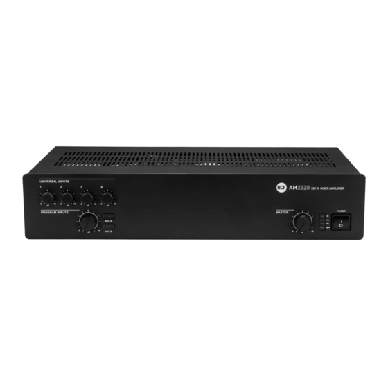
Die beiden Modelle haben identische Eigenschaften bis auf ihre maximale Ausgangsleistung von 160 W (AM2160) bzw. 320 W (AM2320). Die Verstärker besitzen einen Ausgang für niederohmige Lautsprecher (min. 4 Ω) und einen ELA-Ausgang (100 V / 70 V, zum Betrieb von Lautsprechern mit entsprechenden Transformatoren).
14 17 16 13 ZWEI RJ45-BUCHSEN (Kanäle 2 und 3) zum Anschluss je eines Durchsagemikrofons RCF BM 3001. Bemerkung: wenn ein Durchsagemikrofon BM 3001 angeschlossen ist, müssen die Kanal-DIP- Schalter 3 und 4 auf die Betriebsart „–20 dBu + PHANTOM“ gestellt sein (siehe unten, 10).
Seite 40
VIER SYMMETRISCHE SIGNALEINGÄNGE (Kanäle 1, 2, 3, 4) mit Schraubleisten- Anschlüssen. Nichtinvertierender Audioeingang – Invertierender Audioeingang Masse (Abschirmung) Vorranganforderung (aktiv, wenn mit GND verbunden) JEDER DER VIER KANÄLE HAT VIER DIP-SCHALTER. IN 1 OFF – CHIME OFF: die Gongfunktion ist CHIME: die Gongmelodie deaktiviert.
Seite 41
Der Verstärker addiert die beiden Kanäle einer an den AUX INPUT A angeschlossenen Stereoquelle intern (zu einem Monosignal); dies gilt auch für eine an AUX INPUT B angeschlossene Stereoquelle. GAIN-REGLER (EINGANGSEMPFINDLICHKEIT) FÜR DEN AUX INPUT A. EINGANG DES AUX INPUT B MIT ZWEI CINCH-BUCHSEN. GAIN-REGLER (EINGANGSEMPFINDLICHKEIT) FÜR DEN AUX INPUT B.
Ohne Vorrang geschlossen Maximale Spannung an den Kontakten: 24 V; maximaler Strom: 0,5 A AUSGANG VOM VERSTÄRKER (AM2160: max. 160 W, AM2320: max. 320 W) ZU DEN LAUTSPRECHERN (ELA-Leitung 100 V / 70 V oder Impedanz 4 Ω). Benutzen Sie immer nur einen dieser Ausgänge (lesen Sie den Abschnitt „Lautsprecheranschlüsse“).
Seite 43
DIP 2 DIP 3 BETRIEBSART Nur die zuerst eintreffende Vorranganforderung von Kanal 1-4 (ebenso Vox von Kanal 1, wenn mit Vorrang-DIP-Schalter 4 ermöglicht) hat Gültigkeit. Jegliche nachfolgend eintreffende … I/LCK INTERLOCKED Vorranganforderung hat erst Gültigkeit, wenn die vorherige endet. Bemerkung: das einzige nachfolgend aktivierbare Ereignis (das auch einen vorherigen Vorrang außer Kraft setzen kann) ist ein CHIME SEQUENTIAL COMMAND.
Eine Impedanz von weniger als 4 Ω führt zu einer schädlichen Überlastung des POWER OUTPUT Verstärkers. Bei der Wahl der Lautsprechermodelle ist die Maximalleistung des Verstärkers (AM2160: 100V 160 W, AM2320: 320 W, jeweils an 4 Ω) zu berücksichtigen. Die Lautsprecherkabel sollten so kurz wie möglich sein; längere Kabel können höhere Leitungsquerschnitte erfordern.
NETZSPANNUNGSEINSTELLUNG WICHTIG: Dieser Abschnitt der Bedienungsanleitung ist nur für qualifiziertes Personal bestimmt. Die folgenden Anleitungen sind vom Benutzer zu ignorieren. Stellen Sie sicher, dass das Gerät nicht mit der Netzspannung verbunden ist (ziehen Sie den Netzstecker). Entfernen Sie das Deckelblech. In Bild 1 ist der Stecker für den Wechsel der Netzspannung durch ein Rechteck hervorgehoben.