Emerson EXD-U00 Einbauanleitung
Schrittmotorsteuerung für elektrische regelventile ex4 - ex8
Verfügbare Sprachen
Verfügbare Sprachen
Quicklinks
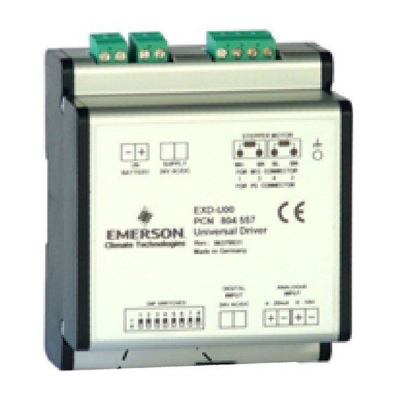
EXD-U00 Universal Driver Module is for driving
Emerson stepper motor driven electrical control
valves series EX4/EX5/EX6/EX7/EX8.
!
Safety instructions:
• Read operating instruction thoroughly. Failure
to comply can result in device failure, system
damage or personal injury.
• It is intended for use by persons having the
appropriate knowledge and skill.
• Switch off all voltages / currents before cabling.
• Comply with local electrical regulations when
wiring.
• Do not operate system before all cable
connections are completed.
• Do not apply 110/220/230V to any terminal of
driver module
Setting
Do not apply voltage to the driver before
completion of wiring and setting of dip switches.
Universal
driver
needs
no
configuration by means of dip switches for
application of different valve, different analogue
input signal and type of start mode (see fig. 1).
Function
Dip Switch Number
1 2 3 4 5 6 7 8
EX4/EX5/EX6
0 1 1 0 1 0 - -
EX7
1 0 0 1 0 1 - -
EX8
1 1 0 1 1 1 - -
4-20mA analogue input signal - - - - - - - 0
0-10V analogue input signal
- - - - - - - 1
With start mode (Fig.3b)
- - - - - - 1 -
Without start mode (Fig.3a)
- - - - - - 0 -
Installation and wiring
• Install electrical control valve in system according
to operating instructions of valve. For hot gas
bypass applications install the valve as far as
possible from discharge valve of compressor. Inlet
EXD-U_65072__R05.doc
Universal Driver Module EXD-U00
for Electrical Control Valves EX4 ... EX8
gas temperature to the valve should not exceed
80°C. Contact Emerson for higher temperatures.
Warning: Install valve with electrical
connector in downward position.
• Install Driver Module and other external electronic
devices which need to be connected to driver.
• Set-up all wire connections as shown in wiring
diagram (see Fig. 2).
• Keep separate the wires for power supply, stepper
motor of valve and signal.
• Recommended wire cross section between 0.5
2
mm
and 2.5 mm
Start-up procedure
• Do not apply voltage to the driver before
completion of wiring and setting of dip switches.
• Do not operate the driver and valve when the
system is under vacuum or without refrigerant
except for closing valve before charging of system.
• Vacuum the entire system.
• Warning: The valves are delivered at half open
position. Do not charge system before closure of
setting
except
valve in case of expansion valve and hot gas
bypass application.
• To close valve apply supply voltage to driver
module for the following times without applying
digital input signal 24V to terminals of EXD-U00:
Valve
EX4/EX5/EX6
EX7/EX8
• After closure of valve, interrupt power supply to
driver module and charge the system with
refrigerant.
• Start the system and check operating conditions.
Valve Synchronisation:
Stepper motor driven valves are synchronized with
the reference point in the fully closed position and
the controller is reset when the digital input is open.
For synchronisation the digital input must be
interrupted for 10 sec, at least once a week.
Operating Instructions
2
.
Time, seconds
min: 2
max: 30
min: 6
max: 30
Date: 25.09.2008
Technical data, power supply:
• Main supply voltage: 24V AC/DC (+10%, -15%),
50-60Hz. Power supply line to driver to be
protected by 1.0A external fuse.
• Use a safety class II transformer. Minimum power
required 20VA.
• Emergency supply voltage Ub (from ECP-024):
+18 Vdc.
Inputs:
• 1 analogue input 4-20mA, burden 364Ω, or 1
analogue input 0-10V, impedance 27kΩ.
• 1 Digital input: 24VAC/DC (+10%, -15%), 50-
60Hz.
Outputs:
4 current outputs for stepper motor of EX4 / EX5 /
•
EX6 / EX7 / EX8.
Nominal current: 0.5A for EX4 / EX5 / EX6,
•
0.75A for EX7 and 0.8A for EX8.
Maximum cable length: 6 meter AWG20/22.
•
Uninterruptible power supply ECP-024
• Power supply voltage: 24 VAC ± 10%
• Power outputs: Two, each +18VDC
Wiring Diagram see Fig. 2
(3) = Fuse 1.0A
(4) = DIN plug for connection to EX8 (prior to
March 2008 production)
(5) = Plug cable assembly EX5-Nxx for connection
to EX4/EX5/EX6/EX7 and EX8(new)
(6) = Controller supplies 4...20mA or 0...10V
(7) = Digital input signal (0V = OFF; 24V = ON)
(8) = Analogue input signal (4...20mA or 0...10V)
(9) = Optional
Uninterruptible
insures the closure of valve during power
failures in systems, where a valve with
positive shut-off function is needed
Cable color code
WH =
White
BK =
Black
BL =
Blue
BN =
Brown
GB
Power
Supply
PCN 864752

Verwandte Anleitungen für Emerson EXD-U00


Inhaltszusammenfassung für Emerson EXD-U00
-
Seite 2: Sicherheitshinweise
Regelventilen der überschreiten. Bei höheren Temperaturen wenden • Versorgungsspannung: 24V AC/DC (+10%, -15%), Baureihe EX4/EX5/EX6/EX7/EX8 eingesetzt. Sie sich bitte an Emerson. 50-60Hz (mit 1,0 A absichern) Achtung: Regelventil mit elektrischem Stecker • Transformator Klasse II verwenden, Nennleistung:...