Sony XR-CA400 Betriebsanleitung
Vorschau ausblenden
Andere Handbücher für XR-CA400:
- Anleitung (2 Seiten) ,
- Bedienungsanleitung (124 Seiten)
Inhaltsverzeichnis
Quicklinks
SERVICE MANUAL
Ver 1.2 2002.07
Cassette player section
Tape track
Wow and flutter
Frequency response
Signal-to-noise ratio
Tuner section
FM
Tuning range
Aerial terminal
Intermediate frequency
Usable sensitivity
Selectivity
Signal-to-noise ratio
Harmonic distortion at 1 kHz
Separation
Frequency response
MW/LW
Tuning range
Aerial terminal
Intermediate frequency
Sensitivity
Sony Corporation
9-870-235-13
2002G0500-1
e Vehicle Company
C 2002.07
Published by Sony Engineering Corporation
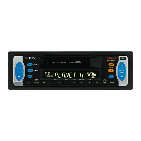
XR-CA400/CA410
Photo: XR-CA400
SPECIFICATIONS
Power amplifier section
4-track 2-channel stereo
Outputs
0.08 % (WRMS)
30 – 18,000 Hz
Speaker impedance
Maximum power output 50 W × 4 (at 4 ohms)
Cassette type
General
TYPE II, IV
61 dB
Outputs
TYPE I
58 dB
Input
87.5 – 108.0 MHz
External aerial connector
Tone controls
10.7 MHz/450 kHz
8 dBf
Power requirements
75 dB at 400 kHz
66 dB (stereo),
Dimensions
72 dB (mono)
Mounting dimensions
0.6 % (stereo),
0.3 % (mono)
Mass
35 dB at 1 kHz
Supplied accessories
30 – 15,000 Hz
MW: 531 – 1,602 kHz
LW: 153 – 279 kHz
Design and specifications are subject to change
External aerial connector
without notice.
10.7 MHz/450 kHz
MW: 30 µV
LW: 40 µV
FM/MW/LW CASSETTE CAR STEREO
Model Name Using Similar Mechanism
Tape Transport Mechanism Type
Speaker outputs
(sure seal connectors)
4 – 8 ohms
Audio output
Power aerial relay control
lead
Power amplifier control
lead
Telephone ATT control
lead
Bass ±9 dB at 100 Hz
Treble ±9 dB at 10 kHz
12 V DC car battery
(negative earth)
Approx. 178 × 50 × 176 mm
(w/h/d)
Approx. 182 × 53 × 161 mm
(w/h/d)
Approx. 1.2 kg
Parts for installation and
connections (1 set)
Front panel case (1)
AEP Model
UK Model
NEW
MG-25L-136
Inhaltsverzeichnis

Verwandte Anleitungen für Sony XR-CA400


Inhaltszusammenfassung für Sony XR-CA400
- Seite 1 Design and specifications are subject to change Aerial terminal External aerial connector without notice. Intermediate frequency 10.7 MHz/450 kHz MW: 30 µV Sensitivity LW: 40 µV FM/MW/LW CASSETTE CAR STEREO Sony Corporation 9-870-235-13 2002G0500-1 e Vehicle Company C 2002.07 Published by Sony Engineering Corporation...
-
Seite 2: Inhaltsverzeichnis
XR-CA400/CA410 TABLE OF CONTENTS Notes on chip component replacement • Never reuse a disconnected chip component. • Notice that the minus side of a tantalum capacitor may be dam- GENERAL aged by heat. Location of Controls ............3 Setting the Clock ............. 3 Flexible Circuit Board Repairing •... -
Seite 3: General
XR-CA400/CA410 SECTION 1 This section is extracted from instruction manual. GENERAL Location of controls Setting the clock The clock uses a 24-hour digital indication. Example: To set the clock to 10:08 Press (DSPL) for two seconds. The hour indication flashes. - Seite 4 XR-CA400/CA410 AUDIO OUT BUS AUDIO IN BUS CONTROL IN BUS AUDIO IN Source selector* Signalquellenwähler* Sélecteur de source* Selettore di fonte* Geluidsbronkiezer* BUS CONTROL IN * not supplied nicht mitgeliefert non fourni non in dotazione niet meegeleverd * Note for the aerial connecting * Nota per il collegamento dell’antenna...
- Seite 5 XR-CA400/CA410 Parts list (1) Teileliste (1) Liste des composants (1) Elenco dei componenti (1) Onderdelenlijst (1) The numbers in the list are keyed to those in the instructions. Die Nummern in der Liste sind dieselben wie im Erläuterungstext. Les numéros de l’illustration correspondent à ceux des I numeri nella lista corrispondono a quelli riportati nelle istruzioni.
- Seite 6 XR-CA400/CA410 (OFF) (RELEASE) Dashboard Fire wall Armaturenbrett Motorraumtrennwand Tableau de bord Séparation moteur/ Cruscotto habitacle Dashboard Parete frangifiamma Brandschot 1 8 2 Bend these claws outward for a tight fit, if necessary. Falls erforderlich, diese Klammern für einen sicheren Halt hochbiegen.
-
Seite 7: Disassembly
XR-CA400/CA410 SECTION 2 DISASSEMBLY Note: Follow the disassembly procedure in the numerical order given. MECHANISM DECK (MG-25L-136) 5 screw (PTT2.6 × 6) 6 mechanism deck (MG-25L-136) 4 connector (CN351) 3 flexible board (CNP301) 2 sub panel assy 1 screw (PTT2.6 × 6) 1 four screws (PTT2.6 ×... - Seite 8 XR-CA400/CA410 HEAT SINK (ISO) 1 three screws (PTT2.6 × 10) 2 heat sink (ISO) 1 four screws (PTT2.6 × 10)
-
Seite 9: Assembly Of Mechanism Deck
XR-CA400/CA410 SECTION 3 ASSEMBLY OF MECHANISM DECK Note: Follow the assembly procedure in the numerical order given. HOUSING 7 Hold the hanger by bending the claw. 5 Fit projection on C part. 1 Install the catch to the hanger. 2 Install the hanger onto two claws of the housing. - Seite 10 XR-CA400/CA410 LEVER (LDG-A) / (LDG-B) shaft A shaft A shaft B shaft B shaft C 1 Fit the lever (LDG-A) on 3 type-E stop ring 2.0 shafts A – C and install it. 2 Fit the lever (LDG-B) on shafts A and B and install it.
- Seite 11 XR-CA400/CA410 GUIDE (C) 2 guide (C) 1 three claws MOUNTING POSITION OF CAPSTAN/REEL MOTOR (M901) two precision screws (P2 × 2) capstan/reel motor (M901) Note: Mount the motor so that the angle between of the motor and the hole for the becomes 30 °...
-
Seite 12: Mechanical Adjustments
XR-CA400/CA410 SECTION 4 SECTION 5 MECHANICAL ADJUSTMENTS ELECTRICAL ADJUSTMENTS 1. Clean the following parts with a denatured-alcohol-moistened TAPE DECK SECTION 0 dB=0.775 V swab: playback head pinch roller Tape Speed Adjustment rubber belt capstan Setting: idler 2. Demagnetize the playback head with a head demagnetizer. -
Seite 13: Diagrams
XR-CA400/CA410 SECTION 6 DIAGRAMS 6-1. NOTE FOR PRINTED WIRING BOARDS AND SCHEMATIC DIAGRAMS Note on Printed Wiring Board: Note on Schematic Diagram: • All capacitors are in µF unless otherwise noted. pF: µµF • X : parts extracted from the component side. -
Seite 14: Ic Block Diagrams
XR-CA400/CA410 • IC Block Diagrams – MAIN Board – IC51 SAA6588T-118 POWER SUPPLY PAUSE & RESET DETECTOR MULTI PATH 57kHz DETECTOR 8th ORDER BAND-PASS FILTER CLOCKED SIGNAL QUALITY COMPARATOR DECODER CLOCK CLOCK RDS/RDBS RDS/RDBS INTERFACE DATA DEMODULATOR DECODER REGISTER DATA... - Seite 15 XR-CA400/CA410 IC331 TDA7402TR IC351 LB1930M-TLM BUFFER 33 32 31 24 23 OUT1 MOTOR CONTROL DRIVE CIRCUIT MIXER CIRCUIT OUT2 BUFFER MONO- MONO- MONO- MONO- MONO- MONO- P-GND S-GND FADER FADER FADER FADER FADER FADER ACINLF FRONT SUBWOOFER SWINR ACIN +PHASE...
-
Seite 16: Printed Wiring Board - Main Board
XR-CA400/CA410 6-2. PRINTED WIRING BOARD – MAIN Board – BUS AUDIO AUDIO OUT REAR REMOTE IN BUS CONTROL CN781 (FRONT VIEW) F781 REAR RCH+ FRONT RCH+ FRONT LCH+ REAR LCH+ GRN/BLK REAR LCH– WHT/BLK FRONT LCH– GRY/BLK FRONT RCH– VIO/BLK REAR RCH–... -
Seite 17: Schematic Diagram - Main Board (1/3)
XR-CA400/CA410 6-3. SCHEMATIC DIAGRAM – MAIN Board (1/3) – • • See page 13 for Waveform. See page 14 for IC Block Diagrams. (Page 18) (Page 19) -
Seite 18: Schematic Diagram - Main Board (2/3)
XR-CA400/CA410 6-4. SCHEMATIC DIAGRAM – MAIN Board (2/3) – • • See page 13 for Waveforms. See page 14 for IC Block Diagrams. (Page 17) (Page 19) -
Seite 19: Schematic Diagram - Main Board (3/3)
XR-CA400/CA410 6-5. SCHEMATIC DIAGRAM – MAIN Board (3/3) – • See page 14 for IC Block Diagrams. (Page 17) (Page 21) (Page 18) -
Seite 20: Printed Wiring Board - Key Board
XR-CA400/CA410 Ver 1.2 6-6. PRINTED WIRING BOARD – KEY Board – KEY BOARD (COMPONENT SIDE) LSW901 – 904, 907 – 915 LSW905, 906 LSW901 S902 S903 S908 SOURCE + (VOLUME) LSW905 > D-BASS LED903 (ILLUMINATION) LSW906 S905 LCD901 (LIQUID CRYSTAL DISPLAY) -
Seite 21: Schematic Diagram - Key Board
XR-CA400/CA410 6-7. SCHEMATIC DIAGRAM – KEY Board – • See page 13 for Waveform. (Page 19) -
Seite 22: 6-8. Ic Pin Function Description
FLASH_W Not used (open) BUSON Bus on/off control signal output to the SONY bus interface (IC581) “L”: bus on TESTIN Setting terminal for the test mode “L”: test mode, normally fixed at “H” Input of acknowledge signal for the key entry Acknowledge signal is input to accept function... - Seite 23 XR-CA400/CA410 Pin No. Pin Name Description Power on/off control signal output of the loading motor drive (IC351) and capstan/reel motor TAPEON (M901) “H”: motor on CMON Capstan/reel motor (M901) drive signal output terminal “H”: motor on Front panel block remove/attach detection signal input NOSESW “L”: front panel is attached, “H”: front panel is removed...
-
Seite 24: Exploded Views
XR-CA400/CA410 SECTION 7 EXPLODED VIEWS NOTE: • -XX and -X mean standardized parts, so they • Items marked “*” are not stocked since they may have some difference from the original are seldom required for routine service. Some one. delay should be anticipated when ordering •... - Seite 25 3-224-861-01 PANEL, FRONT BACK 3-224-898-01 PANEL, FRONT (CA400) 3-225-121-01 BUTTON (R/CE) (MBP. D) 3-224-898-11 PANEL, FRONT (CA410) 3-225-124-01 BUTTON (EJECT/CE) (Z) 3-042-504-01 EMBLEM (NO.2.5), SONY * 67 3-225-128-01 PLATE (R), LIGHT GUIDE 3-225-118-01 BUTTON (+/-) (CA400) 3-225-119-01 BUTTON (S/A) 3-225-118-11 BUTTON (+/-) (CA410) (+ >...
- Seite 26 XR-CA400/CA410 (3) MECHANISM DECK SECTION (MG-25L-136) HP901 M901 not supplied Ref. No. Part No. Description Remark Ref. No. Part No. Description Remark A-3291-667-A CLUTCH (FR) ASSY 3-933-346-01 CATCHER * 152 3-019-130-01 LEVER (LDG-A) 3-933-344-01 GUIDE (C) * 153 3-019-131-01 LEVER (LDG-B)
-
Seite 27: Electrical Parts List
XR-CA400/CA410 SECTION 8 ELECTRICAL PARTS LIST NOTE: • Due to standardization, replacements in the • Items marked “*” are not stocked since they When indicating parts by reference number, please include the board. parts list may be different from the parts speci- are seldom required for routine service. - Seite 28 XR-CA400/CA410 Ref. No. Part No. Description Remark Ref. No. Part No. Description Remark LSW913 1-771-882-11 SWITCH, TACTILE (WITH LED) (REP, 3) R942 1-216-808-11 METAL CHIP 1/16W (CA410: AMBER) R943 1-216-808-11 METAL CHIP 1/16W LSW913 1-786-106-11 SWITCH, TACTILE (WITH LED) (REP, 3)
- Seite 29 XR-CA400/CA410 MAIN Ref. No. Part No. Description Remark Ref. No. Part No. Description Remark A-3326-771-A MAIN BOARD, COMPLETE (CA410: AMBER) C181 1-124-233-11 ELECT 10uF A-3326-772-A MAIN BOARD, COMPLETE C183 1-163-251-11 CERAMIC CHIP 100PF (CA400/CA410: GREEN) C184 1-107-823-11 CERAMIC CHIP 0.47uF...
- Seite 30 XR-CA400/CA410 MAIN Ref. No. Part No. Description Remark Ref. No. Part No. Description Remark C585 1-126-933-11 ELECT 100uF D724 8-719-079-42 DIODE 1ZB22 (TPA3) C611 1-126-157-11 ELECT 10uF D731 8-719-079-42 DIODE 1ZB22 (TPA3) C615 1-126-157-11 ELECT 10uF D732 8-719-079-42 DIODE 1ZB22 (TPA3)
- Seite 31 XR-CA400/CA410 MAIN Ref. No. Part No. Description Remark Ref. No. Part No. Description Remark JC701 1-216-295-11 SHORT 1-216-001-00 METAL CHIP 1/10W JC702 1-216-295-11 SHORT 1-216-057-00 METAL CHIP 2.2K 1/10W 1-216-025-11 RES-CHIP 1/10W JC751 1-216-296-11 SHORT 1-216-097-11 RES-CHIP 100K 1/10W JC752...
- Seite 32 XR-CA400/CA410 MAIN Ref. No. Part No. Description Remark Ref. No. Part No. Description Remark R514 1-216-097-11 RES-CHIP 100K 1/10W R607 1-249-399-11 CARBON 1/4W R515 1-216-097-11 RES-CHIP 100K 1/10W R608 1-249-399-11 CARBON 1/4W R516 1-216-097-11 RES-CHIP 100K 1/10W R609 1-249-397-11 CARBON...
- Seite 33 XR-CA400/CA410 Ref. No. Part No. Description Remark Ref. No. Part No. Description Remark PARTS FOR INSTALLATION AND CONNECTIONS ************** HARDWARE LIST ************************************** ************** X-3373-602-1 FRAME ASSY 7-685-792-09 SCREW +PTT 2.6X6 (S) X-3366-405-1 SCREW ASSY (EXP), FITTING 7-685-647-79 SCREW +BVTP 3X10 TYPE2 N-S 3-225-732-01 COLLAR 7-685-794-09 SCREW +PTT 2.6X10 (S)
-
Seite 34: Revision History
XR-CA400/CA410 REVISION HISTORY Clicking the version allows you to jump to the revised page. Also, clicking the version at the upper right on the revised page allows you to jump to the next revised page. Ver. Date Description of Revision 2001.01...