
Verwandte Anleitungen für Gewiss GW 10 793


Inhaltszusammenfassung für Gewiss GW 10 793
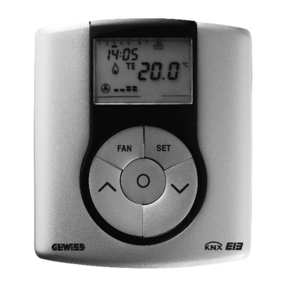
- Seite 1 Termostato EIB - da parete EIB wall thermostat Thermostat EIB - mural Termóstato EIB - de pared EIB Thermostat für Wandmontage GW 10 793 GW 14 793...
-
Seite 3: Inhaltsverzeichnis
INDICE pag. AVVERTENZE GENERALI Contenuto della confezione ..........4 DESCRIZIONE GENERALE In breve . -
Seite 4: Avvertenze Generali
L’organizzazione di vendita GEWISS è a disposizione per chiarimenti e informazioni tecniche. Gewiss SpA si riserva il diritto di apportare modifiche al prodotto descritto in questo manuale in qualsiasi momento e senza alcun preavviso. Contenuto della confezione n. -
Seite 5: Descrizione Generale
DESCRIZIONE GENERALE In breve Il Termostato EIB - da parete consente di gestire la temperatura dell’ambiente in cui è installato. La regolazione della temperatura viene effettuata comandando, attraverso il bus KNX/EIB del sistema di Building Automation, gli attuatori KNX/EIB che controllano gli elementi di riscaldamento o condizionamento, compresi i fan coil. - Seite 6 DESCRIZIONE GENERALE Impostazione modalità di funzionamento • da bus con oggetti distinti a 1 bit (OFF, ECONOMY, PRECOMFORT, COMFORT); • da bus con oggetto a un byte. Misura temperatura • con sensore integrato o sonda di temperatura; • misto con definizione del peso relativo. Controllo temperatura a zone •...
-
Seite 7: Elementi Di Comando E Visualizzazione Posteriori
DESCRIZIONE GENERALE Elementi di comando e visualizzazione posteriori Tasto di programmazione indirizzo fisico LED di programmazione indirizzo fisico... -
Seite 8: Posizione Dei Comandi
DESCRIZIONE GENERALE Posizione dei comandi Il termostato è dotato di un display LCD retroilluminato e di cinque pulsanti di comando sempre accessibili. -
Seite 9: Descrizione Comandi
DESCRIZIONE GENERALE Descrizione comandi PULSANTI DI COMANDO Simbolo Pag. Regolazione velocità fan coil Regolazione temperatura (+) / Selezione parametri Selezione modalità funzionamento / conferma Regolazione temperatura (–) / Selezione parametri Impostazione parametri SEGNALAZIONI A DISPLAY Modalità di funzionamento automatico del fan coil collegato AUTO Modalità... -
Seite 10: Modalità Di Controllo
DESCRIZIONE GENERALE Modalità di controllo Il termostato può essere impostato in 2 differenti modalità di controllo: • Slave: il funzionamento dipende dal dispositivo configurato come Master (ad esempio il cronotermostato EIB GW 10 791), che imposta tipo, modalità di funzionamento o set point del termostato in funzione della parametrizzazione ETS. - Seite 11 DESCRIZIONE GENERALE SIGNIFICATO DI Riscaldamento Condizionamento Simbolo Modalità Modalità Set point Set point funzionamento funzionamento Economy Comfort ECONOMY COMFORT Precomfort Precomfort PRECOMFORT PRECOMFORT Comfort Economy COMFORT ECONOMY Il funzionamento antigelo è attivo solo in riscaldamento, a impianto di termoregolazione spento (OFF). In questo caso il termostato utilizza il set point di temperatura antigelo impostato, riattivando l’impianto di riscaldamento solo se la temperatura ambientale scende...
-
Seite 12: Istruzioni D'impiego
ISTRUZIONI D’IMPIEGO Durante il funzionamento, l’attivazione del riscaldamento o del condizionamento sono segnalate nel modo seguente: Riscaldamento Il simbolo indica che il comando di attivazione è stato inviato all’attuatore di comando della caldaia o dell’elettrovalvola di zona. Se via ETS sono state attivate le notifiche dal carico e il termostato non riceve dall’attuatore il riscontro dell’avvenuta attuazione, il simbolo inizia a... - Seite 13 ISTRUZIONI D’IMPIEGO È possibile impostare i seguenti parametri: Tipo di funzionamento (riscaldamento/condizionamento) Giorno della settimana Minuti Unità di misura della temperatura Se via ETS è stata abilitata la modifica dei set point da locale sono visibili e modificabili localmente anche i seguenti parametri: Riscaldamento Condizionamento - Set Point...
- Seite 14 ISTRUZIONI D’IMPIEGO Per scorrere la sequenza, confermando il valore del parametro visualizzato, premere il tasto finché non appare il parametro che si desidera modificare. L’uscita dalla procedura di impostazione dei parametri avviene premendo nuovamente il tasto SET oppure, automaticamente, dopo 30 secondi dall’ultima digitazione. Per impostare i parametri di riscaldamento e condizionamento occorre eseguire entrambe le sequenze (nella seconda sequenza si possono confermare i parametri uguali, modificando solo quelli specifici).
- Seite 15 ISTRUZIONI D’IMPIEGO Impostazione unità di misura temperatura Quando il simbolo °C o °F della temperatura inizia a lampeggiare, selezionare l’unità di misura della temperatura con i tasti Per confermare il valore impostato, premere il tasto entro 30 secondi. - Impostazione Set Point (riscaldamento) risc All’apparire del simbolo...
- Seite 16 ISTRUZIONI D’IMPIEGO - Impostazione Set Point (riscaldamento) risc All’apparire del simbolo , il valore di temperatura inizia a lampeggiare. Regolare il valore di ) con i COMFORT tasti Per confermare il valore impostato, premere il tasto entro 30 secondi. - Impostazione Set Point (condizionamento) cond All’apparire del simbolo...
- Seite 17 ISTRUZIONI D’IMPIEGO P05 - Logica di controllo All’apparire della scritta P05, viene visualizzata la logica di controllo dell’impianto di termoregolazione. (00 = controllo a 2 punti, 01 = controllo proporzionale, 02 = controllo fan coil) La logica di controllo dell’impianto di termoregolazione non può...
- Seite 18 ISTRUZIONI D’IMPIEGO CONTROLLO PROPORZIONALE Il termostato controlla, al termine di ogni tempo di ciclo, la temperatura ambientale e, in base alla differenza riscontrata con il set point impostato, modula le attivazioni e disattivazioni della caldaia (PWM) oppure invia un comando il valore di controllo dell'elemento riscaldante o raffrescante (controllo continuo).
- Seite 19 ISTRUZIONI D’IMPIEGO ISCALDAMENTO ventola spenta set point 3risc 2risc 1risc valvola ON valvola OFF ONDIZIONAMENTO ventola spenta set point 1cond 2cond 3cond valvola OFF valvola ON Per evitare continue commutazioni, il termostato può attendere fino a 2 minuti prima di inviare il comando di attivazione all’attuatore che controlla l’impianto di termoregolazione o ai canali dell’attuatore che comandano le velocità...
- Seite 20 ISTRUZIONI D’IMPIEGO ATTENZIONE: Per il controllo delle velocità fan coil, con comandi di tipo ON/OFF, se non si dispone di attuatore con interblocco, si raccomanda l'abilitazione delle notifiche dall'attuatore comandato e il link degli oggetti relativi nella configurazione del progetto ETS. In tal caso (ad esempio nel passaggio da V1 a V2) il termostato invia un comando di attivazione velocità...
- Seite 21 ISTRUZIONI D’IMPIEGO P08 - Valore percentuale minimo per invio comando All'apparire della scritta P08, impostare la risoluzione percentuale di invio del comando al dispositivo di controllo della termoregolazione. I possibili valori sono: 5%, 10%, 20%. Per confermare il valore impostato, premere il tasto entro 30 secondi.
- Seite 22 ISTRUZIONI D’IMPIEGO P12 - Valore differenziale di regolazione Velocità 3 All'apparire della scritta P12, impostare il valore differenziale di regolazione velocità V3. Possibili valori: da 0,2 °C a 2 °C, con passo di 0,1 °C. Per confermare il valore impostato, premere il tasto entro 30 secondi.
-
Seite 23: Forzatura Temporanea Della Temperatura
ISTRUZIONI D’IMPIEGO P15 - Abilitazione dei comandi remoti di impostazione modalità e tipo di funzionamento All’apparire della scritta P15, abilitare o disabilitare i comandi remoti con i tasti (OFF = comandi remoti disabilitati, ON = comandi remoti abilitati) L’abilitazione è segnalata sul display dal simbolo L’abilitazione dei comandi remoti permette di impostare da remoto il tipo e la modalità... -
Seite 24: Parametri Preimpostati
ISTRUZIONI D’IMPIEGO Parametri preimpostati Giorno della settimana 1: lunedì 00:01 16 °C 18 °C Set point temperatura di riscaldamento 20 °C 5 °C ANTIGELO 24 °C 26 °C Set point temperatura di condizionamento 28 °C 35 °C PROTEZIONE ALTE TEMPERATURE Unità... -
Seite 25: Comportamento Alla Caduta E Al Ripristino Dell'alimentazione Bus
ISTRUZIONI D’IMPIEGO Comportamento alla caduta e al ripristino dell’alimentazione bus Alla caduta dell’alimentazione bus il dispositivo non compie alcuna azione. Ora e data sono mantenute dall’alimentazione tampone (batteria ricaricabile), mentre tutte le altre impostazioni sono conservate in una memoria non volatile. Con alimentazione fornita esclusivamente dalla batteria si ha un’autonomia di 36 ore nelle seguenti condizioni: •... -
Seite 26: Sostituzione Batteria
ISTRUZIONI D’IMPIEGO Sostituzione batteria Togliere la vite di fissaggio, che si trova sotto il dispositivo, e staccare il termostato dalla base di supporto, seguendo la sequenza illustrata in figura. Togliere il coperchietto di chiusura del vano batteria e sostituire la batteria ricaricabile con un’altra dello stesso tipo (ML1220) rispettando le polarità... -
Seite 27: Pulizia Del Termostato
ISTRUZIONI D’IMPIEGO Riagganciare il termostato sulla base di supporto, seguendo la sequenza illustrata in figura, e fissarlo nuovamente con la vite posta sotto il dispositivo. ATTENZIONE - Se il termostato non è stato alimentato dal bus durante la sostituzione della batteria, riaggiornare data e ora. - Non gettare la batteria nel fuoco. -
Seite 28: Istruzioni D'installazione
ISTRUZIONI D’INSTALLAZIONE ATTENZIONE: l’installazione del dispositivo deve essere effettuata esclusivamente da personale qualificato, seguendo la normativa vigente e le linee guida per le installazioni KNX/EIB. Corretto posizionamento Per la corretta rilevazione della temperatura dell’ambiente controllare, il termostato non deve essere installato in nicchie, vicino a porte finestre, accanto... -
Seite 29: Avvertenze Per L'installazione Knx/Eib
ISTRUZIONI D’INSTALLAZIONE Montaggio su scatola tonda (o quadrata) Avvertenze per l’installazione KNX/EIB 1. La lunghezza della linea bus tra il termostato EIB e l’alimentatore non deve superare i 350 metri. 2. La lunghezza della linea bus tra il termostato EIB e il più lontano dispositivo KNX/EIB da comandare non deve superare i 700 metri. -
Seite 30: Connessioni Elettriche
ISTRUZIONI D’INSTALLAZIONE ATTENZIONE: i cavi di segnale del bus non utilizzati e il conduttore di continuità elettrica non devono mai toccare elementi sotto tensione o il conduttore di terra. Connessioni elettriche Schema delle connessioni elettriche 1. Prima di procedere alla connessione al bus KNX/EIB, inserire la batteria ricaricabile per la memoria tampone (vedere paragrafo Sostituzione batteria). - Seite 31 ISTRUZIONI D’INSTALLAZIONE 3. Inserire il morsetto bus negli appositi piedini del dispositivo. Il corretto senso di inserzione è determinato dalle guide di fissaggio.
-
Seite 32: Completamento
ISTRUZIONI D’INSTALLAZIONE Completamento Agganciare il termostato sulla base di supporto, seguendo la sequenza illustrata in figura, e fissarlo con la vite in dotazione. -
Seite 33: Dati Tecnici
DATI TECNICI Comunicazione Bus KNX/EIB Alimentazione Tramite bus KNX/EIB, 29 V dc SELV + 1 batteria ricaricabile tipo ML1220 3 V per l’aggiornamento data/ora in caso di assenza tensione bus Assorbimento corrente dal bus 5 mA Cavo bus KNX/EIB TP1 Elementi di comando 5 pulsanti frontali 1 tasto miniatura di programmazione indirizzo... - Seite 35 CONTENTS page GENERAL INFORMATION Pack content ............36 GENERAL DESCRIPTION Summary .
-
Seite 36: General Information
The GEWISS sales organisation is at your disposal for clarifications and technical information. Gewiss SpA reserves the right to make changes to the product described in this manual at any time and without giving any notice. Pack content n. -
Seite 37: General Description
GENERAL DESCRIPTION Summary The EIB wall thermostat allows you to manage the temperature in the area it is installed in. The temperature is regulated by the KNX/EIB actuators which are managed by the Building Automation KNX/EIB bus and control the heating or air-conditioning elements, including the fan coils. - Seite 38 GENERAL DESCRIPTION Setting the operation mode • from the bus with separate 1 bit objects (OFF, ECONOMY, PRECOMFORT, COMFORT); • from the bus with 1 byte objects. Temperature reading • with integrated sensor or temperature probe; • mixed with definition of the relative weight. Temperature control in zones •...
-
Seite 39: Control Elements And Rear Display
GENERAL DESCRIPTION Control elements and rear display Physical address programming key Physical address programming LED... -
Seite 40: Position Of The Commands
GENERAL DESCRIPTION Position of the commands The thermostat is fitted with a backlit LCD display and 5 control buttons which are always accessible. -
Seite 41: Command Description
GENERAL DESCRIPTION Command description CONTROL BUTTONS Symbol Page Fan-coil speed regulation Temperature regulation (+) / Select settings Select operation mode / confirmation Temperature regulation (-) / Select settings Setting parameters VDU SIGNALS Auto operation mode for the connected fan coil AUTO Manual operation mode for the connected fan coil Thermostat in operation mode OFF... -
Seite 42: Control Mode
GENERAL DESCRIPTION Control mode The thermostat can be set to 2 different control modes: • Slave: operations depend on the device set as the Master (for example, the EIB GW 10 791 timer-thermostat), that sets the type, operation mode or set point for the thermostat according to ETS settings. - Seite 43 GENERAL DESCRIPTION MEANING OF Heating Air conditioning Symbol Operation Operation Set point Set point mode mode Economy Comfort ECONOMY COMFORT Precomfort Precomfort PRECOMFORT PRECOMFORT Comfort Economy COMFORT ECONOMY The frostprotect function is only enabled in heating function mode, when the thermal regulation system is OFF. In this case the thermostat uses the set frostprotect set-point re-starting the heating system only when the ambient temperature decreases below T...
-
Seite 44: Setting Parameters
OPERATING INSTRUCTIONS During operation, the activation of. the heating or air-conditioning functions are indicated as followed: Heating symbol indicates that the activation command has been sent to the actuator which controls the boiler or the zone electrovalve. If the load notice has been sent via the ETS and the thermostat does not receive confirmation from the actuator that the same has been activated, the symbol starts to flash. - Seite 45 OPERATING INSTRUCTIONS It is possible to set the following parameters: Operation type (heating/air conditioning) Day of the week Hours Minutes Temperature unit of measurement If local set point changes are enabled via ETS, the following parameters are also displayed and editable locally: Heating Air conditioning - Set Point...
- Seite 46 OPERATING INSTRUCTIONS To scroll the sequence, confirming the values displayed on the screen, press the until you reach the parameter you want to change. Press the SET key again to exit the parameter setting procedure or it will exit automatically after a 30" time-out. It is necessary to perform both sequences to set the heating and air-conditioning parameters (in the second sequence it is possible to confirm the parameters which are the same, and just change the specific ones).
- Seite 47 OPERATING INSTRUCTIONS Setting the temperature unit of measurement When the temperature symbol °C or °F starts to blink, select the temperature unit of measurement using the keys. Press the key within 30 seconds to confirm the value set. - Set Point setting (heating) heat The temperature value starts to blink when the...
- Seite 48 OPERATING INSTRUCTIONS - Set Point setting (heating) heat The temperature value starts to blink when the symbol appears. Regulate the value (T ) using the COMFORT keys. Press the key within 30 seconds to confirm the value set. - Set Point (air conditioning) setting cond The temperature value starts to blink when the...
- Seite 49 OPERATING INSTRUCTIONS P05 - Control logic When P05 appears on the screen, the thermal regulation system control logic is displayed. (00 = 2 point control, 01 = proportional control, 02 = fan coil control) The thermal regulation system control logic cannot be changed locally.
- Seite 50 OPERATING INSTRUCTIONS PROPORTIONAL CONTROL At the end of each cycle time, the thermostat controls the ambient temperature and, based on the difference found with the set point, turns the boiler on or off (PWM) or sends a heating or cooling control value command (constant control).
- Seite 51 OPERATING INSTRUCTIONS EATING fan OFF set point 3heat 2heat 1heat valve ON valve OFF IR CONDITIONING fan OFF set point 1cond 2cond 3cond valve OFF valve ON To avoid continuous switchings, the thermostat will wait for up to 2 minutes before sending the activation command to the actuator that controls the thermal regulation system or to the actuator channels that control the fan coil speed.
- Seite 52 OPERATING INSTRUCTIONS WARNING: For fan coil speed control with ON/OFF type commands, if there is no actuator with interlock, enabling notifications from the controlled actuator and object link for ETS project configuration is recommended. In this case (for example, when switching from V1 to V2) the thermostat sends a start V2 speed command only after receiving notification on V1 speed command contact opening (switch from speed OFF).
- Seite 53 OPERATING INSTRUCTIONS P08 - Minimum percentage value to send the command When the P08 code appears on the screen, set the percentage resolution to send the command to the thermal regulation control device. The values available are as follows: 5%, 10%, 20%. Press the key within 30 seconds to confirm the value set.
- Seite 54 OPERATING INSTRUCTIONS P12 - Speed 3 regulation differential value When the P12 appears on the display, set the differential regulation value to speed V3. Possible values: from 0.2 °C to 2 °C with a pitch of 0.1 °C. Press the key within 30 seconds to confirm the value set.
-
Seite 55: Temporary Temperature Forcing
OPERATING INSTRUCTIONS P15 - Enable remote control mode and operation type settings When P15 appears, enable or disable remote controls using keys. (OFF = remote controls OFF, ON = remote controls ON) The symbol on the display indicates that this option is enabled. -
Seite 56: Default Parameters
OPERATING INSTRUCTIONS Default parameters Day of the week 1: Monday Time 00:01 16 °C 18 °C Heating temperature set-point 20 °C 5 °C FROSTPROTECT 24 °C 26 °C Air-conditioning temperature set-point 28 °C 35 °C HIGH TEMPERATURE PROTECTION Temperature unit of measurement °C Control logic 2 points... -
Seite 57: Behaviour On The Failure And Reinstatement Of The Bus Power Supply
OPERATING INSTRUCTIONS Behaviour on the failure and reinstatement of the bus power supply When the bus power supply fails, the device performs no actions. The time and date are maintained by the buffer power system (rechargeable battery) whilst all the other settings are saved to a non-volatile memory. -
Seite 58: Replacing The Battery
OPERATING INSTRUCTIONS Replacing the Battery Remove the fastener screws which are under the device, and remove the thermostat from the support base, as seen in the figure below. Remove the battery holder cover and replace the rechargeable battery with one of the same type (ML1220), paying attention to the direction of the poles. -
Seite 59: Cleaning The Thermostat
OPERATING INSTRUCTIONS Replace the thermostat in the support base, as seen in the figure below, and replace the screws under the device. WARNING - If the thermostat was not powered by the bus whilst replacing the battery, update the time and date. - Never throw the battery into a fire. -
Seite 60: Installation Instructions
INSTALLATION INSTRUCTIONS WARNING: the installation of the device must be exclusively done by qualified personnel, following the regulations in force and the guidelines for KNX/EIB installations. Correct installation position In order for the thermostat to take correct readings of the ambient temperature, it must not be installed in an alcove, near a door or window, next to radiators or air conditioner... -
Seite 61: Warnings For Knx/Eib Installation
INSTALLATION INSTRUCTIONS Mounting on a round (or square) box Warnings for KNX/EIB installations 1. The length of the bus line between the EIB thermostat and the power supply unit must not exceed 350 metres. 2. The length of the bus line between the EIB thermostat and the most distant KNX/EIB device must not exceed 700 metres. -
Seite 62: Electrical Connections
INSTALLATION INSTRUCTIONS WARNING: the unused bus signal cables and the electrical continuity conductor must never touch elements under power or the earth conductor. Electrical connections Electrical connections diagram 1. Before connecting the KNX/EIB bus, insert the rechargeable buffer memory battery (see Replacing the Battery paragraph). - Seite 63 INSTALLATION INSTRUCTIONS 3. Insert the bus connector into the special feet of the device. The fastener guides determine the direction it should be inserted.
-
Seite 64: Completing Installation
INSTALLATION INSTRUCTIONS Completing installation Position the thermostat on the support base, as seen in the figure below, and fix it in place using the supplied screws. -
Seite 65: Technical Data
TECHNICAL DATA Communication KNX/EIB Bus Power supply By KNX/EIB Bus, 29 V dc SELV + 1 rechargeable battery type ML1220 3 V to update date/time in the event bus power is out Bus current consumption 5 mA Bus wire KNX/EIB TP1 Control elements 5 front buttons 1 mini physical address programming key... - Seite 67 SOMMAIRE page AVERTISSEMENTS GÉNÉRAUX Contenu de la confection ..........68 DESCRIPTION GENERALE En bref .
-
Seite 68: Avertissements Généraux
L’organisation de vente de la Société GEWISS est à votre disposition pour tous éclaircissements et toutes informations techniques. Gewiss SpA se réserve le droit de faire des modifications sur le produit décrit dans ce manuel à n’importe quel moment et sans aucun préavis. -
Seite 69: Description Generale
DESCRIPTION GENERALE En bref Le Thermostat EIB - mural permet de gérer la température de la pièce où il est installé. Le thermostat effectue le réglage de la température en commandant, par le biais du bus Ç KNX/EIB du système de Home Automation, les actionneurs KNX/EIB qui contrôlent les éléments de chauffage ou de climatisation, y compris les fan coils. - Seite 70 DESCRIPTION GENERALE Programmation du mode de fonctionnement • par bus avec objets distincts à 1 bit (ARRET, ECONOMIE, PRECONFORT, CONFORT); • par bus avec objet à un byte. Mesure de la température • avec capteur intégré ou sonde de température; •...
-
Seite 71: Eléments De Commande Et D'affichage Postérieurs
DESCRIPTION GENERALE Eléments de commande et d’affichage postérieurs Touche de programmation adresse physique LED de programmation adresse physique Ç... -
Seite 72: Position Des Commandes
DESCRIPTION GENERALE Position des commandes Le thermostat est muni d’un afficheur LCD rétroéclairé et de cinq boutons de commande toujours accessibles. -
Seite 73: Description Des Commandes
DESCRIPTION GENERALE Description des commandes BOUTONS DE COMMANDE Symbole Page Réglage de la vitesse du fan coil Réglage de la température (+) / Sélection des paramètres Sélection du mode de fonctionnement / confirmation Réglage de la température (-) / Sélection des paramètres Programmation des paramètres SIGNALISATIONS SUR L’AFFICHEUR Mode de fonctionnement automatique du fan coil connecté... -
Seite 74: Modalité De Contrôle
DESCRIPTION GENERALE Modalité de contrôle Le thermostat peut être réglé en 2 modalités de contrôle différentes : • Slave le fonctionnement dépend du dispositif configuré comme Master (par exemple le chronothermostat EIB GW 10 791), qui programme le type, le mode de fonctionnement ou le set point du thermostat en fonction de la paramétrisation ETS. - Seite 75 DESCRIPTION GENERALE SIGNIFICATION DE Chauffage Climatisation Symbole Mode de Mode de Set-point Set-point fonctionnement fonctionnement Economie Confort ÉCONOMIE CONFORT Préconfort Préconfort PRÉCONFORT PRÉCONFORT Confort Economie CONFORT ÉCONOMIE Le fonctionnement antigel n’est activé qu’en modalité chauffage, avec l’installation de régulation thermique éteinte (ARRET).
-
Seite 76: Instructions D'utilisation
INSTRUCTIONS D'UTILISATION Pendant le fonctionnement, l’activation du chauffage ou de la climatisation est signalée de la façon suivante : Chauffage Le symbole indique que la commande d’activation a été envoyée à l’actionneur de commande de la chaudière ou de l’électrovanne de zone. Si via ETS les notifications ont été activées par la charge et que le chronothermostat ne reçoit pas de l'actionneur la réponse que l'activation a été... - Seite 77 INSTRUCTIONS D'UTILISATION Il est possible de programmer les paramètre suivants : Type de fonctionnement (chauffage/climatisation) Jour de la semaine Heures Minutes Unité de mesure de la température Si via ETS la modification des set points au niveau local, les paramètres suivants sont aussi visibles et modifiables localement: Chauffage Climatisation...
- Seite 78 INSTRUCTIONS D'UTILISATION Pour faire défiler la séquence, en confirmant la valeur du paramètre affiché, appuyer sur la touche jusqu’à ce que le paramètre que l’on désire modifier apparaisse. Pour sortir de la procédure de programmation des paramètres, appuyer à nouveau sur la touche SET, ou bien la sortie se fera automatiquement, 30 secondes après la dernière fois qu'on a appuyé...
- Seite 79 INSTRUCTIONS D'UTILISATION Programmation de l’unité de mesure de la température Lorsque le symbole °C ou °F de la température commence à clignoter, il faut sélectionner l’unité de mesure de la température avec les touches Pour confirmer la valeur programmée, appuyer sur la touche dans les 30 secondes qui suivent.
- Seite 80 INSTRUCTIONS D'UTILISATION - Programmation du Set-point (chauffage) chauff Quand le symbole apparaît, la valeur de température commence à clignoter. Régler la valeur de CONFORT avec les touches Pour confirmer la valeur programmée, appuyer sur la touche dans les 30 secondes qui suivent. - Programmation du Set-point (climatisation) climat...
- Seite 81 INSTRUCTIONS D'UTILISATION P05 - Logique de contrôle Quand le message P05 apparaît, la logique de contrôle de l'installation de régulation thermique est affichée . (00 = contrôle à 2 points, 01 = contrôle proportionnel, 02 = contrôle fan coil) La logique de contrôle de l'installation de régulation thermique ne peut pas être modifiée localement.
- Seite 82 INSTRUCTIONS D'UTILISATION CONTRÔLE PROPORTIONNEL A la fin de chaque temps de cycle le thermostat contrôle la température ambiante et, en fonction de la différence trouvée avec le set point programmé, il module les activations et les désactivations de la chaudière (PWM), ou bien il envoie une commande avec une valeur de contrôle de l’élément chauffant ou refroidissant (contrôle continu).
- Seite 83 INSTRUCTIONS D'UTILISATION HAUFFAGE hélice éteinte set-point 3chauff 2chauff 1chauff soupape MARCHE soupape ARRET LIMATISATION Ç hélice éteinte set-point 1climat 2climat 3climat soupape ARRET soupape MARCHE Pour éviter des commutations continuelles, le thermostat peut attendre jusqu’à 2 minutes avant d’envoyer la commande d’activation à...
- Seite 84 INSTRUCTIONS D'UTILISATION ATTENTION : Pour contrôler les vitesses du fan coil, avec des commandes du type MARCHE/ARRET, si l'on ne dispose pas d'un actionneur avec interblocage, il est recommandé d'activer les notifications de l'actionneur commandé et le link des objets relatifs dans la configuration du projet ETS. Dans ce cas (par exemple, dans le passage de V1 à...
- Seite 85 INSTRUCTIONS D'UTILISATION P08 - Valeur pourcentage minimum pour l’envoi commande Quand le message P08 apparaît, programmer la résolution pourcentage d’envoi de la commande au dispositif de contrôle de la régulation thermique. Les valeurs possibles sont : 5%, 10%, 20%. Pour confirmer la valeur programmée, appuyer sur la touche dans les 30 secondes qui suivent.
- Seite 86 INSTRUCTIONS D'UTILISATION P12 - Valeur du différentiel de réglage Vitesse 3 Lorsque le message P12 apparaît, programmer la valeur du différentiel de réglage vitesse V3. Valeurs possibles: de 0,2 °C à 2 °C, avec un pas de 0,1 °C. Pour confirmer la valeur programmée, appuyer sur la touche dans les 30 secondes qui suivent.
-
Seite 87: Forçage Temporaire De La Température
INSTRUCTIONS D'UTILISATION P15 - Activation des commandes à distance pour programmer le type et le mode de fonctionnement Quand le message P15 apparaît, activer ou désactiver les commandes à distance avec les touches (ARRET = commandes à distance désactivées, MARCHE = commandes à distance activées) L’activation est signalée sur l'afficheur par le symbole L’activation des commandes à... -
Seite 88: Paramètres Préréglés
INSTRUCTIONS D'UTILISATION Paramètres préréglés Jour de la semaine 1: lundi Heure 00:01 16 °C 18 °C Set point de la température de chauffage 20 °C 5 °C ANTIGEL 24 °C 26 °C Set point de la température de climatisation 28 °C 35 °C PROTECTION HAUTES TEMPERAT Unité... -
Seite 89: Comportement À La Chute Et Au Rétablissement De L'alimentation Bus
INSTRUCTIONS D'UTILISATION Comportement à la chute et au rétablissement de l’alimentation bus A la chute de l’alimentation du bus, le dispositif n’effectue aucune action. L’heure et la date sont maintenues par l’alimentation de secours (pile rechargeable), tandis que tous les autres réglages sont conservés dans une mémoire non volatile. Avec l’alimentation fournie exclusivement par la pile on a une autonomie de 36 heures dans les conditions suivantes : •... -
Seite 90: Remplacement De La Pile
INSTRUCTIONS D'UTILISATION Remplacement de la pile Enlever la vis de fixation qui se trouve sous le dispositif, et détacher le thermostat de la base de support, en suivant la séquence illustrée sur la figure. Enlever le petit couvercle de fermeture du logement de la pile, et remplacer la pile rechargeable par une autre pile du même type (ML1220), tout en respectant les... -
Seite 91: Nettoyage Du Thermostat
INSTRUCTIONS D'UTILISATION Raccrocher le thermostat sur la base de support, en suivant la séquence illustrée sur la figure, et le fixer à nouveau avec la vis située sous le dispositif. ATTENTION - Si le thermostat n’a pas été alimenté par le bus pendant le remplacement de la pile, il faut remettre à... -
Seite 92: Instructions Pour L'installation
INSTRUCTIONS POUR L'INSTALLATION ATTENTION : l’installation du dispositif ne doit être effectuée que par du personnel qualifié, conformément à la réglementation en vigueur et aux lignes directrices pour les installations KNX/EIB. Positionnement correct Pour pouvoir détecter correctement la température de la pièce à contrôler, le thermostat ne doit pas être installé... -
Seite 93: Avertissements Pour L'installation Du Knx/Eib
INSTRUCTIONS POUR L'INSTALLATION Montage sur une boîte ronde (ou carrée) Avertissements pour l’installation du KNX/EIB 1. La longueur de la ligne bus entre le thermostat EIB et l’alimentateur ne doit pas dépasser 350 mètres. Ç 2. La longueur de la ligne bus entre le thermostat EIB et le dispositif KNX/EIB à commander le plus éloigné... -
Seite 94: Connexions Électriques
INSTRUCTIONS POUR L'INSTALLATION ATTENTION : les câbles de signal du bus non utilisés et le conducteur de continuité électrique ne doivent jamais toucher des éléments sous tension ni le conducteur de terre. Connexions électriques Schéma des connexions électriques 1. Avant de procéder à la connexion au bus KNX/EIB, insérer la pile rechargeable pour la mémoire de secours (voir le paragraphe Remplacement de la pile). - Seite 95 INSTRUCTIONS POUR L'INSTALLATION 3. Brancher la borne bus dans les pieds du dispositif prévus. Le sens correct d’insertion est déterminé par les guides de fixation. Ç...
-
Seite 96: Achèvement
INSTRUCTIONS POUR L'INSTALLATION Achèvement Accrocher le thermostat sur la base de support, en suivant la séquence illustrée sur la figure, et le fixer avec la vis fournie. -
Seite 97: Donnees Techniques
DONNÉES TECHNIQUES Communication Bus KNX/EIB Alimentation Avec bus KNX/EIB, 29 V cc SELV + 1 pile rechargeable du type ML1220 3 V pour la mise à jour de la date et de l’heure en cas d’absence de la tension au bus Absorption du courant par le bus 5 mA Câble bus... - Seite 99 ÍNDICE pág. ADVERTENCIAS GENERALES Contenido del embalaje ..........100 DESCRIPCIÓN GENERAL En breve .
-
Seite 100: Advertencias Generales
La organización de venta GEWISS se encuentra a disposición para informaciones técnicas. Gewiss SpA se reserva el derecho de aportar cambios al producto descrito en este manual en cualquier momento y sin preaviso. Contenido del embalaje n. -
Seite 101: Descripción General
DESCRIPCIÓN GENERAL En breve El Termostato EIB - de pared permite controlar la temperatura del ambiente en el que se ha instalado. La regulación de la temperatura se efectúa controlando, a través del bus KNX/EIB del sistema de Building Automation, los actuadores KNX/EIB que controlan los elementos de calefacción o acondicionamiento, incluidos los fan-coil. - Seite 102 DESCRIPCIÓN GENERAL Programación modalidad de funcionamiento • desde bus con objetos diferentes de 1 bit (OFF, ECONÓMICO, PRECONFORT, CONFORT); • desde bus con objeto a un byte. Medida temperatura • con sensor integrado o sonda de temperatura; • mixto con definición del peso relativo. Control temperatura de zonas •...
-
Seite 103: Elementos De Mando Y Visualización Posteriores
DESCRIPCIÓN GENERAL Elementos de mando y visualización posteriores Tecla de programación dirección física LED de programación dirección física Ñ... -
Seite 104: Posición De Los Mandos
DESCRIPCIÓN GENERAL Posición de los mandos El termostato está dotado de una pantalla LCD retroiluminada y de cinco pulsadores de mando siempre accesibles. -
Seite 105: Descripción Mandos
DESCRIPCIÓN GENERAL Descripción mandos PULSADORES DE MANDO Símbolo Pág. Regulación velocidad fan coil Regulación temperatura (+) / Selección parámetros Selección modalidad funcionamiento / confirmación Regulación temperatura (-) / Selección parámetros Configuración parámetros SEÑALIZACIONES EN LA PANTALLA Modalidad de funcionam. autom. del fan coil conectado AUTO Modalidad de funcionam. -
Seite 106: Modalidad De Control
DESCRIPCIÓN GENERAL Modalidad de control El termostato puede programarse en 2 diferentes modalidades de control: • Slave el funcionamiento depende del dispositivo configurado como Master (por ejemplo el cronotermostato EIB GW 10 791), que programa tipo, modalidad de funcionamiento o set point del termostato según la parametrización ETS. En el primer caso (modalidad), el termóstato usa los set point configurados por ETS, que pueden ser modificados localmente y por bus si estas opciones han sido habilitadas en la configuración ETS. - Seite 107 DESCRIPCIÓN GENERAL SIGNIFICADO DE Calefacción Acondicionamiento Símbolo Modalidad Modalidad Set point Set point funcionamiento funcionamiento Económico Confort ECONÓMICO CONFORT Preconfort Preconfort PRECONFORT PRECONFORT Confort Económico CONFORT ECONÓMICO El funcionamiento antihielo está activo solo en calefacción, de instalación de termorregulación apagada (OFF). En este caso el termostato utiliza el set point de temperatura antihielo programado, reactivando la instalación de calefacción solo si la temperatura ambiental...
-
Seite 108: Configuración Parámetros
INSTRUCCIONES DE USO Durante el funcionamiento, la activación de la calefacción o del acondicionamiento están señaladas de la manera siguiente: Calefacción El símbolo indica que el mando de activación se ha enviado al actuador de mando de la caldera o de la electroválvula de zona. - Seite 109 INSTRUCCIONES DE USO Es posible programar los siguientes parámetros: Tipo de funcionamiento (calefacción/acondicionamiento) Día de la semana Horas Minutos Unidad de medida temperatura Si mediante ETS se ha habilitado la modificación de los set point desde local, son visibles y modificables también los siguientes parámetros: Calefacción Acondicionamiento - Set Point...
- Seite 110 INSTRUCCIONES DE USO Para desplazar la secuencia, confirmando el valor del parámetro visualizado, presionar la tecla hasta que no aparezca el parámetro que se desea modificar. La salida del procedimiento de programación de los parámetros se efectúa presionando nuevamente la tecla SET o, automáticamente, después de 30 segundos desde la última vez que ha pulsado.
- Seite 111 INSTRUCCIONES DE USO Programación unidad de medida temperatura Cuando el símbolo °C o °F de la temperatura empieza a parpadear, seleccionar la unidad de medida de la temperatura con las teclas Para confirmar el valor programado, presionar la tecla antes de 30 segundos. - Programación Set Point (calefacción) calef...
- Seite 112 INSTRUCCIONES DE USO - Programación Set Point (calefacción) calef Cuando aparezca el símbolo , el valor de temperatura empezará a parpadear. Regular el valor de CONFORT con las teclas Para confirmar el valor programado, presionar la tecla antes de 30 segundos. - Programación Set Point acond (acondicionamiento)
- Seite 113 INSTRUCCIONES DE USO P05 - Lógica de control Al aparecer la leyenda P05, se visualiza la lógica de control de la instalación de termorregulación. (00 = control de 2 puntos, 01 = control proporcional, 02 = control fan coil) La lógica de control de la instalación de termorregulación no puede modificarse localmente.
- Seite 114 INSTRUCCIONES DE USO CONTROL PROPORCIONAL El termostato controla, al final de cada tiempo de ciclo, la temperatura ambiente y según la diferencia observada con el set point programado, modula las activaciones y desactivaciones de la caldera (PWM) o envía un mando con un valor de control del elemento calentador o de enfriado (control continuo).
- Seite 115 INSTRUCCIONES DE USO ALEFACCIÓN ventilador apagado set point 3calef 2calef 1calef válvula ON válvula OFF CONDICIONAMIENTO ventilador apagado set point Ñ 1acond 2acond 3acond válvula OFF válvula ON Para evitar continuas conmutaciones, el termostato puede esperar hasta 2 minutos antes de enviar el mando de activación al actuador que controla la instalación de termorregulación o a los canales del actuador que controlan la velocidad del fan coil.
- Seite 116 INSTRUCCIONES DE USO ATENCIÓN: Para el control de velocidades fan coil, con mandos tipo ON/OFF, si no se dispone de un actuador interbloqueo, se recomienda habilitar las notificaciones del actuador mandado y el link de los objetos relativos en la configuración del proyecto ETS.
- Seite 117 INSTRUCCIONES DE USO P08 - Valor de porcentaje mínimo para envío mando Cuando aparezca la nota P08, programar la resolución de porcentaje de envío del mando al dispositivo de control de la termorregulación. Los posibles valores son: 5%, 10%, 20%. Para confirmar el valor programado, presionar la tecla antes de 30 segundos.
- Seite 118 INSTRUCCIONES DE USO P12 - Valor diferencial de regulación Velocidad 3 Cuando aparezca el símbolo P12, programar el valor diferencial de regulación velocidad V3. Posibles valores: de 0,2 °C a 2 °C, con paso de 0,1 °C. Para confirmar el valor programado, presionar la tecla antes de 30 segundos.
-
Seite 119: Forzado Temporal De La Temperatura
INSTRUCCIONES DE USO P15 - Habilitación de los mandos remotos de configuración modalidad y tipo de funcionamiento Cuando aparece la nota P15, habilitar o deshabilitar los mandos remotos con las teclas (OFF = mandos remotos deshabilitados, ON = mandos remotos habilitados) La habilitación está... -
Seite 120: Parámetros Preprogramados
INSTRUCCIONES DE USO Parámetros preprogramados Día de la semana 1: lunes Hora 00:01 16 °C 18 °C Set point temperatura de calefacción 20 °C 5 °C ANTIHIELO 24 °C 26 °C Set point temperatura de acondicionamiento 28 °C 35 °C PROTECCIÓN ALTAS TEMPERATURAS Unidad de medida temperatura °C... -
Seite 121: Comportamiento A La Caída Y Al Reajuste De La Alimentación Bus
INSTRUCCIONES DE USO Comportamiento a la caída y al reajuste de la alimentación bus Al caer la alimentación bus, el dispositivo no lleva a cabo ninguna acción. Hora y fecha se mantienen desde la alimentación tampón (batería recargable), mientras que las demás programaciones se conservan en una memoria no volátil. -
Seite 122: Sustitución Batería
INSTRUCCIONES DE USO Sustitución batería Quitar el tornillo de fijación, que se encuentra debajo del dispositivo, y desenchufar el termostato de la base de soporte, siguiendo la secuencia ilustrada en la figura. Extraer la tapa de cierre de la cavidad batería y cambiar la batería recargable con otra del mismo tipo (ML1220) respetando las polaridades indicadas. -
Seite 123: Limpieza Del Termostato
INSTRUCCIONES DE USO Volver a enganchar el termostato en la base de soporte, siguiendo la secuencia ilustrada en la figura y fijarlo nuevamente con el tornillo colocado debajo del dispositivo. ATENCIÓN - Si el termostato no ha sido alimentado por el bus durante la sustitución de la batería, volver a actualizar fecha y hora. -
Seite 124: Instrucciones De Instalación
INSTRUCCIONES DE INSTALACIÓN ATENCIÓN: la instalación del dispositivo debe efectuarse exclusivamente por personal cualificado, siguiendo la normativa vigente y las líneas guía para las instalaciones KNX/EIB. Correcto posicionamiento Para la correcta detección de la temperatura ambiente controlar, el termostato no debe ser instalado en recintos, cerca de puertas o ventanas, al lado de calefactores o acondicionadores y no... -
Seite 125: Advertencias Para La Instalación Knx/Eib
INSTRUCCIONES DE INSTALACIÓN Montaje en caja redonda (o cuadrada) Advertencias para la instalación KNX/EIB 1. La longitud de la línea bus entre el termostato EIB y el alimentador no debe superar los 350 metros. 2. La longitud de la línea bus entre el termostato EIB y el más lejano dispositivo KNX/EIB a dirigir no debe superar los 700 metros. -
Seite 126: Conexiones Eléctricas
INSTRUCCIONES DE INSTALACIÓN ATENCIÓN: los cables de señal del bus no utilizados y el conductor de continuidad eléctrica no deben nunca tocar elementos bajo tensión o el conductor de tierra. Conexiones eléctricas Esquema de las conexiones eléctricas 1. Antes de proceder a la conexión al bus KNX/EIB, introducir la batería recargable para la memoria tampón (ver parágrafo Sustitución batería). - Seite 127 INSTRUCCIONES DE INSTALACIÓN 3. Introducir la borna bus en los pies específicos del dispositivo. El sentido correcto de inserción está determinado por las guías de fijación. Ñ...
-
Seite 128: Finalización
INSTRUCCIONES DE INSTALACIÓN Finalización Volver a enganchar el termostato en la base de soporte, siguiendo la secuencia ilustrada en la figura y fijarlo con el tornillo suministrado. -
Seite 129: Datos Técnicos
DATOS TÉCNICOS Comunicación Bus KNX/EIB Alimentación Mediante bus KNX/EIB, 29 V cc SELV + 1 batería recargable tipo ML1220 3 V para la actualización de fecha/hora en caso de ausencia tensión bus Absorción corriente desde el bus 5 mA max Cable bus KNX/EIB TP1 Elementos de mando... - Seite 131 INHALTSVERZEICHNIS Seite ALLGEMEINE HINWEISE Packungsinhalt ........... . .132 ALLGEMEINE BESCHREIBUNG Kurzbeschreibung .
-
Seite 132: Allgemeine Hinweise
Die GEWISS Verkaufsabteilung steht für weitergehende Erläuterungen und technische Informationen gerne zur Verfügung. Gewiss S.p.A. behält sich das Recht vor, das in diesem Handbuch beschriebene Produkt jederzeit und ohne Vorankündigung zu ändern. Packungsinhalt 1 St. EIB Thermostattimer für Wandmontage 1 St. -
Seite 133: Allgemeine Beschreibung
ALLGEMEINE BESCHREIBUNG Kurzbeschreibung Das EIB Thermostat für Wandmontage ermöglicht die Temperaturregelung des Raums, in dem es installiert ist. Die Temperaturregelung erfolgt durch Ansteuerung der KNX/EIB-Antriebe der Heizungs- oder Klimaanlage, einschließlich eventueller Fan Coil, über den KNX/EIB-Bus des Building Automation Systems. Im Zusammenspiel mit EIB Thermostattimern für Wandmontage (GW 10 791 - GW 14 791), bei denen über den Bus die Betriebsart und -modus empfangen wird, ermöglicht das Thermostat die Erstellung von Temperaturregelanlagen mit mehreren Zonen. - Seite 134 ALLGEMEINE BESCHREIBUNG Einstellung Betriebsart • über Bus mit eindeutigen Objekten mit 1 Bit (AUS, ABSENKUNG, PREKOMFORT, KOMFORT) • über Bus mit Objekt mit 1 Byte Temperaturmessung • mit integriertem Sensor oder Temperaturfühler • gemischt mit Definition der jeweiligen Wichtung Zonentemperaturüberwachung •...
-
Seite 135: Hintere Bedien- Und Anzeigeelemente
ALLGEMEINE BESCHREIBUNG Hintere Bedien- und Anzeigeelemente Programmiertaste physikalische Adresse LED für Programmierung physikalische Adresse... -
Seite 136: Position Der Bedienelemente
ALLGEMEINE BESCHREIBUNG Position der Bedienelemente Das Thermostat ist mit einem rückbeleuchteten LCD-Display und fünf Steuertasten ausgestattet, die immer zugänglich sind. -
Seite 137: Beschreibung Der Befehle
ALLGEMEINE BESCHREIBUNG Beschreibung der Befehle STEUERTASTEN Symbol Seite Drehzahlregelung Fan Coil Temperaturregelung (+) / Parameterauswahl Auswahl Funktionsmodus / Bestätigung Temperaturregelung (-) / Parameterauswahl Parametereinstellung DISPLAYANZEIGEN Automatische Betriebsart der angeschlossenen Fan Coil AUTO Manuelle Betriebsart der angeschlossenen Fan Coil Thermostat in Betriebsart AUS Betriebsart Geschwindigkeit OFF Fan Coil eingeschaltet... -
Seite 138: Überwachungsmodus
ALLGEMEINE BESCHREIBUNG Überwachungsmodus Das Thermostat kann auf 2 verschiedene Überwachungsmodi eingestellt werden: • Slave: Der Betrieb hängt von dem als Master konfiguriertem Gerät ab (z.B. der EIB Thermostattimer GW 10 791), der die Betriebsart und -modus oder Sollwert des Thermostats entsprechend der ETS-Parametereinstellung vorgibt. Im ersten Fall (Modus) verwendet das Thermostat die über ETS konfigurierten Sollwerte, die lokal und über den Bus modifiziert werden können, falls diese Optionen während der ETS- Konfiguration aktiviert wurden. - Seite 139 ALLGEMEINE BESCHREIBUNG BEDEUTUNG VON Heizung Klimatisierung Symbol Sollwert Betriebsart Sollwert Betriebsart Absenkung Komfort ABSENKUNG KOMFORT Prekomfort Prekomfort PREKOMFORT PREKOMFORT Komfort Absenkung KOMFORT ABSENKUNG Die Frostschutzfunktion ist nur in dem Betriebsmodus Heizung mit ausgeschalteter Temperaturregelung (AUS) aktiv. In diesem Fall verwendet das Thermostat den eingestellten Temperatursollwert für Frostschutz und schaltet die Heizungsanlage nur ein, wenn die Raumtemperatur unter absinkt.
-
Seite 140: Bedienungsanweisung
BEDIENUNGSANWEISUNG Während des Betriebs wird das Einschalten der Heizung oder der Klimatisierung auf die folgende Weise angezeigt: Heizung Das Symbol zeigt an, dass der Einschaltbefehl vom Antrieb der Heizkesselsteuerung oder dem Zonenventil erfasst wurde. Wenn über ETS die Verbraucherbenachrichtigungen aktiviert wurden und der Thermostattimer vom Antrieb nicht die Bestätigung der erfolgten Einschaltung erhält, beginnt das Symbol... - Seite 141 BEDIENUNGSANWEISUNG Folgende Parameter können eingestellt werden: Betriebsmodus (Heizung / Klimatisierung) Wochentag Stunden Minuten Temperatureinheit Wenn über ETS die lokale Änderung der Sollwerte aktiviert wurde, werden auch die folgenden Parameter lokal angezeigt und veränderbar: Heizung Klimatisierung - Sollwert - Sollwert Heiz Klima - Sollwert - Sollwert...
- Seite 142 BEDIENUNGSANWEISUNG Die Taste zum Durchblättern der Sequenz und Bestätigung der angezeigten Werte drücken, bis der Parameter angezeigt wird, der geändert werden soll. Das Verlassen der Parametereinstellprozedur erfolgt durch erneutes Drücken der Taste SET, oder automatisch 30 Sekunden nach dem letzten Tastendruck. Zum Einstellen der Heizungs- und Klimatisierungsparameter müssen beiden Sequenzen ausgeführt werden (in der zweiten Sequenz können die gleichen Parameter bestätigt und nur die Spezifischen geändert werden).
- Seite 143 BEDIENUNGSANWEISUNG Einstellung der Temperatureinheit Wenn das Symbol °C oder °F der Temperatur anfängt zu blinken, kann die Temperatureinheit mit den Tasten gewählt werden. Zur Bestätigung des eingestellten Werts die Taste innerhalb von 30 Sekunden drücken. - Einstellung Sollwert (Heizung) Heiz Bei der Anzeige des Symbols , beginnt der Temperaturwert zu blinken.
- Seite 144 BEDIENUNGSANWEISUNG - Einstellung Sollwert (Heizung) Heiz Bei der Anzeige des Symbols , beginnt der Temperaturwert zu blinken. Den Wert ) mit den Tasten KOMFORT einstellen. Zur Bestätigung des eingestellten Werts die Taste innerhalb von 30 Sekunden drücken. - Einstellung Sollwert (Klimatisierung) Klima Bei der Anzeige des Symbols...
- Seite 145 BEDIENUNGSANWEISUNG P05 - Regellogik Bei der Anzeige von P05, wird die Regellogik der Temperaturregelung angezeigt. (00 = 2-Punkt Regelung, 01 = Proportionalregelung, 02 = Fan Coil Steuerung) Die Regellogik der Temperaturregelung kann lokal nicht geändert werden. Wenn die 2-Punkt Regelung eingestellt wurde, zum Punkt P09 springen, bei Fan Coil zum Punkt P10 gehen, bei Proportionalregelung zum Punkt P06 gehen.
- Seite 146 BEDIENUNGSANWEISUNG PROPORTIONALREGELUNG Das Thermostat prüft am Ende jeder Taktzeit die Raumtemperatur und moduliert je nach festgestellter Abweichung zum eingestellten Sollwert das Ein- und Ausschalten des Heizkessels (PWM) oder sendet einen Befehl für die Steuerung des Heiz- oder Kühlelements (dauernde Regelung). FAN COIL STEUERUNG Beim Erreichen des Temperatursollwerts - (bei...
- Seite 147 BEDIENUNGSANWEISUNG EIZUNG Ventilator ausgeschaltet Sollwert 3Heiz 2Heiz 1Heiz Ventil AN Ventil AUS LIMATISIERUNG Ventilator ausgeschaltet Sollwert 1Klima 2Klima 3Klima Ventil AUS Ventil AN Um ständiges Schalten zu vermeiden, kann der Thermostat bis zu 2 Minuten warten, bevor der Einschaltbefehl dem Antrieb für die Steuerung der Temperaturregelung oder den Kanälen des Antriebs zur Steuerung der Fan Coil Drehzahl geschickt wird.
- Seite 148 BEDIENUNGSANWEISUNG ACHTUNG: Für die Steuerung der Fan Coil Drehzahl mit Regelung Typ AN/AUS wird, falls kein Antrieb mit Verriegelung zur Verfügung steht, die Aktivierung der Benachrichtungen durch den gesteuerten Antrieb empfohlen, und die Verknüpfung der entsprechenden Objekte in der Konfiguration des ETS-Projekts. In diesem Fall (z.B.
- Seite 149 BEDIENUNGSANWEISUNG P08 - Minimaler Prozentwert für Befehlsübermittlung Bei der Anzeige von P08 die prozentuale Auflösung für die Übermittlung des Befehls an das Steuergerät der Temperaturregelung einstellen. Die möglichen Werte sind: 5%, 10%, 20%. Zur Bestätigung des eingestellten Werts die Taste innerhalb von 30 Sekunden drücken.
- Seite 150 BEDIENUNGSANWEISUNG P12 - Differenzwert der Regelung Drehzahl 2 Bei der Anzeige von P12, den Differenzwert der Regelung Drehzahl V3 einstellen. Mögliche Werte: Von 0,2 °C bis 2 °C, mit Schritten von 0,1 °C. Zur Bestätigung des eingestellten Werts die Taste innerhalb von 30 Sekunden drücken.
-
Seite 151: Kurzzeitiges Übersteuern Der Temperatur
BEDIENUNGSANWEISUNG P15 - Aktivierung Fernsteuerung zur Einstellung Betriebsart- und modus Bei der Anzeige von P15 die Fernbedienung mit den Tasten ein- oder ausschalten. (AUS = Fernbedienung ausgeschaltet, AN = Fernbedienung eingeschaltet) Die Aktivierung wird im Display durch das Symbols angezeigt. Die Aktivierung der Fernbedienung ermöglicht die Ferneinstellung der Betriebsart und -modus, z.B. -
Seite 152: Voreingestellte Parameter
BEDIENUNGSANWEISUNG Voreingestellte Parameter Wochentag 1: Montag Uhrzeit 00:01 16 °C 18 °C Sollwert Heizungstemperatur 20 °C 5 °C FROSTSCHUTZ 24 °C 26 °C Sollwert Klimatisierungstemperatur 28 °C 35 °C ÜBERTEMPERATURSCHUTZ Temperatureinheit °C Regellogik 2-Punkt Differenzwert der Regelung Heizung 0,2 °C 2-Punkt Regelung Klimatisierung 0,5 °C... -
Seite 153: Verhalten Bei Ausfall Und Wiederherstellung Der Busversorgung
BEDIENUNGSANWEISUNG Verhalten bei Ausfall und Wiederherstellung der Busversorgung Bei Ausfall der Busversorgung führt das Gerät keinerlei Aktion aus. Datum und Uhrzeit werden durch die Pufferbatterien (aufladbare Batterie) gespeichert, alle anderen Einstellungen werden in einem nicht flüchtigen Speicher gesichert. Mit reinem Batteriebetrieb steht unter den folgenden Bedingungen eine Autonomie von 36 Stunden zur Verfügung: •... -
Seite 154: Batteriewechsel
BEDIENUNGSANWEISUNG Batteriewechsel Die Befestigungsschraube unter dem Gerät entfernen und das Thermostat gemäß folgender Abbildung vom Haltesockel entfernen. Den Deckel des Batteriefachs entfernen und den entladenen Akku durch einen anderen des gleichen Typs (ML1220) ersetzen, dabei auf die angegebene Polung achten. -
Seite 155: Reinigung Des Thermostats
BEDIENUNGSANWEISUNG Das Thermostat wieder gemäß der in der Abbildung dargestellten Folge auf dem Haltesockel einrasten und wieder mit der Schraube auf der Unterseite befestigen. ACHTUNG - Wenn die Busversorgung des Thermostats während des Batteriewechsels unterbrochen wurde, müssen Datum und Uhrzeit wieder eingestellt werden. - Die Batterie nicht ins Feuer werfen. -
Seite 156: Installationsanweisung
INSTALLATIONSANWEISUNG ACHTUNG: Die Installation des Geräts darf ausschließlich von qualifiziertem Personal gemäß der gültigen Richtlinie und den Installationsrichtlinien für KNX/EIB Installationen erfolgen. Richtige Positionierung Um eine korrekte Erfassung der Raumtemperatur zu gewährleisten, darf das Thermostat nicht in Nischen, neben Türen oder Fenster, neben Heizkörpern oder Klimageräten... -
Seite 157: Hinweise Zur Installation Knx/Eib
INSTALLATIONSANWEISUNG Montage auf rundem (oder eckigem) Gehäuse Hinweise zur Installation KNX/EIB 1. Die Länge der Busleitung zwischen dem EIB Thermostat und dem Netzgerät darf 350 Meter nicht überschreiten. 2. Die Länge der Busleitung zwischen dem EIB Thermostat und dem am weitesten entfernt liegenden, zu steuernden KNX/EIB-Gerät darf 700 Meter nicht überschreiten. -
Seite 158: Elektrische Anschlüsse
INSTALLATIONSANWEISUNG ACHTUNG: nicht verwendeten Bussignalkabel Stromdurchgangsleiter dürfen nie spannungsführende Elemente oder den Erdungsleiter berühren. Elektrische Anschlüsse Elektroanschlussschema 1. Vor dem Anschluss an den KNX/EIB-Bus müss die aufladbare Pufferbatterie eingesetzt werden (siehe Abschnitt Batteriewechsel)). 2. Die rote Ader des Buskabels an die rote Klemme (+) des Terminals und die schwarze Ader an die schwarze Klemme (-) anschließen. - Seite 159 INSTALLATIONSANWEISUNG 3. Die Busklemme in die entsprechenden Steckkontakte des Gerätes einsetzen. Die korrekte Montagerichtung wird durch die Befestigungsführungen vorgegeben.
-
Seite 160: Vervollständigung
INSTALLATIONSANWEISUNG Vervollständigung Das Thermostat gemäß der in der Abbildung dargestellten Folge auf dem Haltesockel einrasten und mit der mitgelieferten Schraube befestigen. -
Seite 161: Technische Daten
TECHNISCHE DATEN Kommunikation KNX/EIB Bus Stromversorgung Über KNX/EIB Bus, 29 V dc SELV + 1 Akku ML1220 3 V für die Aktualisierung Datum/Uhrzeit bei Ausfall der Busspannung Stromaufnahme des Bus 5 mA Buskabel KNX/EIB TP1 Bedienelemente 5 Fronttasten 1 Miniatur-Programmiertaste physikalische Adresse Anzeigeelemente 1 LCD-Display mit LED-Hintergrundbeleuchtung... - Seite 162 xxxxxx N O T E...
- Seite 163 xxxxxxx N O T E...
- Seite 164 According to article 9 paragraph 2 of the European Directive 2004/108/EC the responsible for placing the apparatus on the Community market is: GEWISS S.p.A Via A. Volta, 1 - 24069 Cenate Sotto BG) Italy Tel: +39 035 946 111 Fax: +39 035 945 270 E-mail: qualitymarks@gewiss.com +39 035 946 111 sat@gewiss.com...