
Verwandte Anleitungen für Raychem nvent ETS-05


Inhaltszusammenfassung für Raychem nvent ETS-05
- Seite 1 ETS-05 ELECTRONIC THERMOSTAT ELEKTRONISCHER THERMOSTAT THERMOSTAT ÉLECTRONIQUE TERMOSTATO ELECTRÓNICO TERMOSTATO ELETTRONICO ELEKTRONINEN TERMOSTAATTI...
- Seite 2 ETS-05 Ambient Sensing Line Sensing ENGLISH Installation instructions for nVent RAYCHEM ETS-05 The nVent RAYCHEM ETS-05 Approvals: electronic surface and ambient sensing thermostat provides accurate nVent temperature control for heating cables. The ETS-05 is available in the following 1180 versions:...
- Seite 3 DEUTSCH Montageanleitung nVent RAYCHEM ETS-05 Der nVent RAYCHEM ETS- Zulassungen: 05 ist ein elektronischer nVent Thermostat mit Anlege- und Umgebungstemperaturfühler zur 1180 präzisen Temperaturregelung von II 2(1)G Heizleitungen. Der ETS-05 ist in II 2D den folgenden Ausführungen Ex eb ia mb [Ga] IIC T5 Gb erhältlich:...
- Seite 4 FRANÇAIS Instructions d’installation nVent RAYCHEM ETS-05 Le thermostat de contrôle Agréments : électronique et de température nVent ambiante nVent RAYCHEM ETS-05 assure une régulation 1180 précise de la température des rubans chauffants. Le modèle II 2(1)G II 2D ETS-05 est disponible...
- Seite 5 ESPAÑOL Instrucciones de instalación de nVent RAYCHEM ETS-05 El termostato electrónico de Homologaciones: detección superficial y de ambiente Thermal Management RAYCHEM ETS-05 permite un control preciso de la temperatura de 1180 los cables calefactores. El modelo II 2(1)G ETS-05 II 2D está...
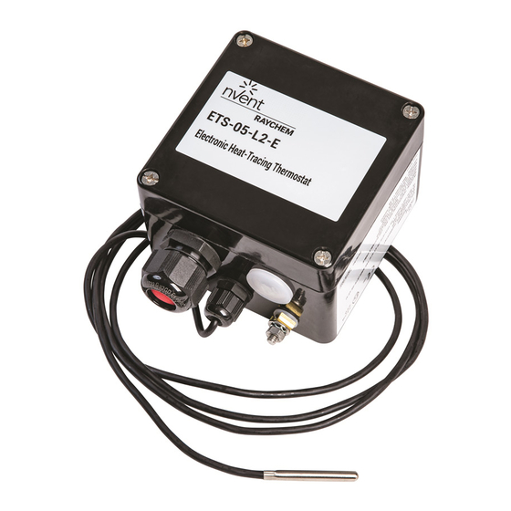
- Seite 6 ITALIANO Istruzioni di installazione per nVent RAYCHEM ETS-05 Il termostato elettronico a contatto Omologazioni: e ambiente RAYCHEM ETS-05 nVent offre un controllo preciso della temperatura per i cavi scaldanti. 1180 L’unità ETS-05 è disponibile nelle seguenti versioni: II 2(1)G ETS-05-L2-E...
- Seite 7 SUOMI nVent RAYCHEM ETS-05 -termostaatin asennusohjeet nVent RAYCHEM ETS-05 on Hyväksynnät: pintalämpötilaa mittaava elektroninen termostaatti lämpökaapeleiden nVent tarkkaan ohjaukseen. ETS-05- termostaatista on saatavana 1180 seuraavat mallit: II 2(1)G ETS-05-L2-E II 2D ETS-05-H2-E Ex eb ia mb [Ga] IIC T5 Gb ETS-05-L1-J Ex tb IIIC T100°C Db IP66...
-
Seite 8: Terminal Block
ETS-05-L2/H2/A2-E TERMINAL BLOCK Relay Out Neutral Out Neutral Supply 230V Supply Earth Earth Earth Terminals 2 and 3 are joined electrically Terminals 5, 6 and 7 are joined electrically *NOTE: Do not remove Earth connecting wire SENSOR/FAILURE MODE SELECT TERMINALS Terminals 1 to 3 allow for the connection of a three wire PT100 sensor. - Seite 9 BORNIER Sortie Sortie Alimentation Alimentation Terre Terre Terre relais neutre neutre 230 V Raccordement électrique des bornes 2 et 3 Raccordement électrique des bornes 5, 6 et 7 *REMARQUE : ne pas retirer le câble de raccordement à la terre. BORNES DE SONDE/ SÉLECTION DE MODE ERREUR Les bornes 1 à...
- Seite 10 MORSETTIERA Relè di Uscita Alimentazione Alimentazione Terra Terra Terra uscita neutra neutra 230 V I morsetti 2 e 3 sono collegati elettricamente I morsetti 5, 6 e 7 sono collegati elettricamente *NOTA: non rimuovere la connessione di messa a terra MORSETTI DI SELEZIONE SENSORE/GUASTO I morsetti da 1 a 3 permettono di collegare un sensore PT100 a tre fili.
- Seite 11 ENGLISH A 1 Thermostat enclosure B 3 mm terminal screwdriver 2 Cable entries (2 x M25) 7 mm screwdriver 3 Temperature sensor terminals Trimming knife 4 Power and Heat Tracing 33 mm spanner (for M25 glands) Terminal blocks (max. 6 mm 19 mm spanner (for M16 glands) 10 mm spanner (for Earth clamp) DEUTSCH...
- Seite 12 ITALIANO A 1 Involucro del termostato B Cacciavite per morsetti 3 mm 2 Ingressi cavi (2 x M25) Cacciavite 7 mm 3 Morsetti per sensori di Spelacavi temperatura Chiave 33 mm 4 Morsettiere per cavi di (per pressacavi M25) alimentazione e tracciamento Chiave 19 mm elettrico (max.
- Seite 13 FRANÇAIS Montage du boîtier ETS-05 (thermostat de contrôle) Différentes possibilités de montage (ne pas le monter sur une sont illustrées (4 trous de montage tuyauterie haute température). M6 à entraxe de 106 x 82 mm). Pour obtenir une meilleure régulation de AVERTISSEMENT: la température, monter le boîtier à...
- Seite 14 ENGLISH Enclosure installation ETS-05-A2-E (ambient sensing thermostat) For optimised temperature control or wet conditions protect the locate the thermostat: thermostat contents from water • as indicated in the system design ingress, by closing lid when not documentation working on the assembly. •...
- Seite 15 FRANÇAIS Montage du boîtier ETS-05-A2-E (thermostat d’ambiance) Pour un meilleur contrôle de la AVERTISSEMENT: Lorsque l’on température ambiante, positionner le travaille par temps humide, thermostat: protéger le thermostat en fermant • en se référant à la documentation le couvercle lorsqu’il n’y a pas relative à...
- Seite 16 ITALIANO Installazione della cassetta ETS-05-A2-E (termostato a rilevamento ambientale) Per un controllo ottimale della proteggere il termostato temperatura, posizionare il dall’ingresso dell’acqua chiudendo termostato: il coperchio, se non per attività • come indicato nella operative. documentazione di progetto del sistema Il sensore ambiente viene fornito •...
- Seite 17 90° ENGLISH Location of the sensor ETS-05 • as indicated in the system design • on lower quadrant of pipe 90° documentation for single heating cable (B) • away from valves, flanges, supports, • on lower quadrant of pipe pumps or other heat sinks centrally between the heating cables if they are two or •...
- Seite 18 ITALIANO Posizione del sensore ETS-05 • come indicato nella documentazione • sul quadrante inferiore del tubo di progetto del sistema a 90° nel caso di cavi scaldanti singoli (B) • lontano da valvole, flange, supporti, pompe o altri dissipatori di calore •...
- Seite 19 FRANÇAIS Fixation de la sonde ETS-05 • Fixer solidement la sonde en deux AVERTISSEMENT: endroits sur le tuyau au moyen du Ne pas installer la sonde si ruban adhésif approprié (D). la température ambiante est • Disposer la sonde parallèlement au inférieure à...
- Seite 20 32 AMP 30 mA ETS-05 PE PE Fail-Safe option Auswahl-funktion Fühlerbruch Mode sécurité Opción a prueba de fallos Opzione failsafe Vikaturvallisuus • Heating cable • Heizband • Ruban chauffant • Cable calefactor • Cavo scaldante Heat Tracing Output on error: •...
- Seite 21 ENGLISH Complete installation ETS-05 Ensure that the pipe and sensor are When thermostat installation is thermally insulated and clad to the complete, test as described in design specification after installation the Testing & Commissioning of thermostat. Section. Retain this instruction Seal cladding with sealant (A).
- Seite 22 ITALIANO ETS-05 Completamento dell’installazione Dopo l’installazione del termostato, Una volta ultimata l’installazione verificare che il tubo e il sensore del termostato, collaudarlo siano isolati termicamente e rivestirli come descritto nella sezione secondo le specifiche di progetto. ‘Collaudo, messa in servizio e Sigillare il rivestimento con un manutenzione’.
- Seite 23 ENGLISH Setting Locate lid and tighten lid screws. If necessary, loosen lid screws and remove lid. Adjust digital switches to switching WARNING: Ensure thermostat is isolated elsewhere for a temperature (°C). The switches minimum of 1 minute before present the setpoint temperature in three digits (100,10, 1).
- Seite 24 ENGLISH Testing, commissioning and maintenance Test heating cable when thermostat – Thermostat operation is correct. installation is complete as directed in – Thermostat setting suites nVent Installation and Maintenance application. manual. – Lid is closed firmly. – Earth wire connecting Earth stud Maintain thermostat during normal to terminal block Earth is present plant maintenance.
- Seite 25 ESPAÑOL Prueba, puesta en marcha y mantenimiento Pruebe el cable calefactor cuando – El termostato funciona finalice la instalación del termostato correctamente. siguiendo las instrucciones – La configuración del termostato del manual de Instalación y es adecuada para la aplicación. mantenimiento de nVent.
- Seite 28 ©2019 nVent. All nVent marks and logos are owned or licensed by nVent Services GmbH or its affiliates. All other trademarks are the property of their respective owners. nVent reserves the right to change specifications without notice. Raychem-IM-EU0227-ETS05-ML-1909 nVent.com | 28...