Inhaltsverzeichnis
Werbung
Verfügbare Sprachen
Verfügbare Sprachen
HWAT-ECO
(Version 4)
Electronic Temperature Control Unit
For energy saving operation of HWAT-R/-M/-L heating cable
Mikroprozessorgesteuerter Temperatursteller
Für den energiesparenden Betrieb der
Temperaturhaltebänder HWAT-R/-M/-L
Modulateur de puissance électronique
Pour une utilisation économique des rubans HWAT-R/-M/-L
Elektronická jednotka řízení teploty
Pro úsporný provoz topného kabelu HWAT-R/-M/-L
Werbung
Kapitel
Inhaltsverzeichnis
Fehlerbehebung

Verwandte Anleitungen für Raychem HWAT-ECO


Inhaltszusammenfassung für Raychem HWAT-ECO
- Seite 1 HWAT-ECO (Version 4) Electronic Temperature Control Unit For energy saving operation of HWAT-R/-M/-L heating cable Mikroprozessorgesteuerter Temperatursteller Für den energiesparenden Betrieb der Temperaturhaltebänder HWAT-R/-M/-L Modulateur de puissance électronique Pour une utilisation économique des rubans HWAT-R/-M/-L Elektronická jednotka řízení teploty Pro úsporný provoz topného kabelu HWAT-R/-M/-L...
- Seite 2 148 mm...
- Seite 3 HWAT -ECO HWAT -ECO HWAT 230V HWAT-ECO...
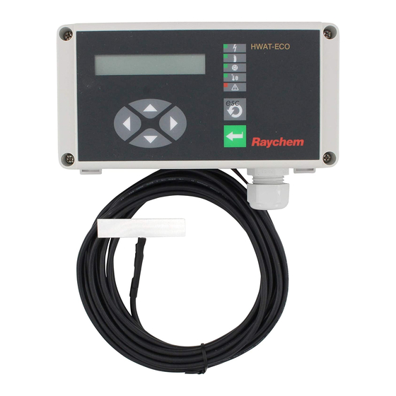
- Seite 4 HWAT-ECO-10 HWAT-ECO-10 Packaging content See diagram in flip-out coverpage The box contains the following parts: HWAT-ECO unit Manual Two screws Two washers Temperature sensor with 4 metre cable Aluminium tape for sensor mounting...
- Seite 5 HWAT-ECO ENGLISH Description of indicator lights, buttons and display ........Contents ..........................1. Description ........................2. Installation ........................3. Operation ........................4. Error/ Alarms and Troubleshooting ..............5. Appendix ........................DEUTSCH Beschreibung der Anzeigeleuchten, Tasten und Anzeige ......Inhalt .............................
-
Seite 6: Inhaltsverzeichnis
1. DESCRIPTION ......................... 1.1 Purpose ........................1.2 Technical data ......................1.3 Care and maintenance ..................2. INSTALLATION ....................... 2.1 Disassembling the unit ..................2.2 Wall mounting instructions ................2.3 Installation of cables and sensors ............... 2.3.1 Wiring diagrams ..................2.3.2 Minimum power cable sizing ............. - Seite 7 4. ERROR/ALARMS and TROUBLESHOOTING ............ 5. APPENDIX ......................... 5.1 Country code ......................5.2 Pipe size, Insulation and Temperature ............5.3 Legionella prevention by temperature shock .......... 5.4 Checklist for problem-free installation and safe operation ....5.4.1 Typical installation schedule for the HWAT-Plus system ..
-
Seite 8: Description
(= MASTER). The other ECOs (= SLAVES) will automatically copy the MASTER settings when connected to it. • HWAT-ECO can be connected to a BMS. The input of a remote DC voltage will set the desired maintain temperature. • An alarm terminal makes errors remotely readable. -
Seite 9: Care And Maintenance
(DIN EN 60730/ VDE 0631-1) 1.3 Care and maintenance To clean the HWAT-ECO use a soft cloth, water and soap, do not use sol- vents. Do not pour water directly on the device. Do not use a water hose or... -
Seite 10: Installation
Several touchable parts inside the unit are directly connected to the mains voltage. The HWAT-ECO has a removable top lid. Both top and bottom of the box have electronic parts and are connected to each other by a 14-pin connec- tor. -
Seite 11: Installation Of Cables And Sensors
2.3 Installation of cables and sensors Tyco Thermal Controls insists on the use of a 30 mA residual current device and a C-characteristic circuit breaker to provide maximum safety and protection from fire. 2.3.1 Wiring diagrams There are three wiring diagrams: C, D and E (see 5.5 Diagrams). pag. -
Seite 12: Sensor Cable
Connect both inside the wires of the sensor to the TEMP terminal in HWAT-ECO. the unit, see Fig. 4. The sensor wires do not have a special polarity. To connect a wire use... -
Seite 13: Network
Connect both wires of the 0-10 V output to the BMS terminal inside the HWAT-ECO, see Fig. 4. Connect the ground wire to the “–” and the 0-10 V output to the “+” terminal. To connect a wire use a screwdriver to push down the orange tab on the side of the terminal Put the wire into the hole and release the orange tab. -
Seite 14: Language
During the quick start the ESC button can be used to go back to a previous menu. On startup the display will show the following text: Press a key to start, and the following Quick install menus appear: Any key to start 3.1.1 Language With the up/down arrow keys you can choose between 5 languages, English, German, French, Danish, Italian and Czech. -
Seite 15: Pre-Programs
The HWAT-ECO has 7 default timer programs. See 5.5.2 Diagrams, page 34 for more information. A pre-program can be selected using the up/ down arrow keys. Press Enter to confirm your choice. HWAT-ECO takes a few seconds to copy the default program to the internal memory. During this time a row of dots will show in the display. -
Seite 16: Menu Overview
A menu can be consulted if further detailed settings (eg. Master/slave, BMS, etc.) are required. You must press a key to access the menu inside the HWAT-ECO. (Pressing ESC shows the current preferred cable temperature.) Pressing another key shows the main menu. There are 6 main menus: Language, Time and Date, Setup, Timer program, Holiday and Info. -
Seite 17: Menu Explanation - Extended Features
Constant temperature 4 Timer program 1 Default program (password check Apartment block if Lock is On) Prison / Barracks Hospital / Nursing Home Hotel Sport centre / Swimming pool Office Edit timer for Monday 2 Edit program Monday Tuesday Edit timer for Tuesday Wednesday Edit timer for Wednesday Thursday... - Seite 18 3. Insulation Set the insulation thickness with the arrow keys. The value can be changed from 9 to 100 mm, but is limited by the pipe diameter. See appendix 5.2, page 23 (‘Pipe size, Insulation and Temperature’) for more information. 4.
-
Seite 19: Timer Program And Legionella Prevention
3.3.2 Timer program and legionella prevention When Lock is ON a password is needed to access the following menus. When lock is OFF the following menus are directly accessable (The display shows a * in the lower right corner). 1. Default program 2. -
Seite 20: Holiday
3.3.3 Holiday This menu is used to set the unit Off, temporarily off or return to timer program. – xx Days off: A number of days can be selected. The unit automatically returns to timer mode when the selected number of days have passed. –... -
Seite 21: Error/Alarms And Troubleshooting
4. ERROR/ALARMS AND TROUBLESHOOTING Please ensure that the unit is correct connected to the power supply and the heating cable is connected to the HWAT-Eco unit. Alarms: Symptom Probable Causes Corrective Actions “ERROR 1” displays 1. Internal temperature of Switch off or disconnect (buzzer beeping HWAT-ECO higher than 65°C... - Seite 22 2. Installed heating cable is (2) Change heating cable type different from the program in HWAT-ECO (can only be selected done in Quickstart). See 3.1.3. 3. Insulation thickness devi- (3) Adjust power correction ates from the required factor.
-
Seite 23: Appendix
5.2 Pipe Size, Insulation and Temperature Pipe size and insulation characteristics have a considerable influence on the temperatures achieved by the HWAT-ECO and the self-regulating tapes. Increasing insulation thickness, better insulating materials and/or smaller pipe sizes generally results in higher temperatures as the heat losses... - Seite 24 The HWAT-ECO internal data is based on standard sets of values for pipe size and insulation characteristics. Any deviations from these standard sets will result in a deviation from the target temperatures. The unit compensates for this by using the ‘Power Correction Factor’.
- Seite 25 Fig. 9 Permitted pipe / insulation combinations Pipe sizes 15 mm 20 mm 25 mm 32 mm 40 mm 50 mm 100 mm Insulation 9 mm 13 mm 20 mm 25 mm 30 mm 40 mm 50 mm 60 mm 70 mm 80 mm 90 mm...
-
Seite 26: Legionella Prevention By Temperature Shock
5.3 Legionella prevention The growth of legionella pneumophila is dependent on temperature: HWAT-R and HWAT-ECO offer the possibility of increasing the water temper- ature by fully powering the HWAT-R. The increased water temperature ena- bles decontamination (measures anti-scalding are essential). Most legionella pneumophila bacteria are killed at 60°C over a period of 30 minutes. - Seite 27 Fig. 10 Example Fig. 11...
- Seite 28 Fig. 12...
-
Seite 29: Checklist For Problem-Free Installation And Safe Operation
5.4 Checklist for problem-free installation and safe operation 5.4.1 Typical installation schedule for hot water temperature maintenance General order of events: l The system is designed and the installation planned. l The pipework is pressure tested or otherwise checked for leaks. l The HWAT-L/R/M cable is tested and then installed on the designated pipes. - Seite 30 Fig. 14 Measurement Instructions for the placing of the heat insulation l For problem-free operation of the self-regulating heating cables, the mate- rial quality and thickness of the thermal insulation are in accordance with the design parameters, and this insulation must be installed correctly. l All the parts of the pipework, including valves, wall transit points, etc.
-
Seite 31: Diagrams
5.5 Diagrams 5.5.1 Diagrams A, B, C, D, E, F, G and H, Installation Sensor positioning Sensor positioning on metal pipes on plastic pipes ATE-180 HW A T -R/-M/-L Pipe/boiler coupling Min. 200 mm HW A T -ECO sensor Min. 200 mm Aluminium tape Insulation Boiler... - Seite 32 MASTER SLAVE 1 SLAVE 2 RS485 RS485 shielded shielded HWAT TEMP HWAT 230V HWAT 230V 230V HW A T -ECO HWAT-ECO Optional TEMP HWAT-ECO TEMP TEMP L ’ N’ L ’ N’ L ’ N’ Alarm Alarm Alarm Temperature Self-regulating...
- Seite 33 Temp (C) >6,4 >64 = Leg. Prevent.
-
Seite 34: Diagram I, Pre-Programs
5.5.2 Diagrams I, Pre-programs = Maintain temp. = Eco temp. = Heating off Constant Monday - Sunday Apartments Max. Monday - Friday Max. Saturday - Sunday Prison Max. Monday - Sunday Hospital / Nursing Home Max. Monday - Sunday... - Seite 35 = Maintain temp. = Eco temp. = Heating off Hotel Max. Monday - Sunday Sport centre / Swimming pool Max. Monday - Sunday Office Max. Monday Max. Tuesday - Thursday Max. Friday Max. Saturday - Sunday...
- Seite 37 Aus, Temp. halten, Spar-Betrieb, Leg. Vorbeugung. Verpackungsinhalt Siehe Darstellung in der Umschlagfaltseite Die Verpackung muss folgende Bestandteile enthalten: • HWAT-ECO-Temperatursteller • Handbuch • zwei Schrauben • zwei Unterlegscheiben • Temperatursensor mit 4 m langem Anschlusskabel • Aluminiumklebeband zur Befestigung des Temperatursensors...
- Seite 38 1. BESCHREIBUNG ......................1.1 Anwendung ......................1.2 Technische Daten ....................1.3 Pflege und Wartung .................... 2. INSTALLATION ......................2.1 Öffnen des Gerätes ....................2.2 Anleitungen für die Wandmontage .............. 2.3 Installation der Kabel und des Temperatursensors ......2.3.1 Anschlussbilder ..................2.3.2 Anschlussquerschnitte der Zuleitungen ........
- Seite 39 4. FEHLER/ALARMMELDUNGEN UND FEHLERBEHEBUNG ......5. ANHANG ..........................5.1 Ländercode (Land) ....................5.2 Rohrdurchmesser, Wärmedämmung und Temperatur ...... 5.3 Legionellenvorbeugung durch Temperaturerhöhung ......5.4 Prüfliste für die reibungslose Installation und den sicheren Betrieb ................... 5.5 Anschlussbilder, Abbildungen und graphische Darstellungen ..
-
Seite 40: Beschreibung
1. BESCHREIBUNG 1.1 Anwendung Der Temperatursteller HWAT-ECO wurde für den Betrieb mit der selbst- regelnden Temperaturhaltebandreihe HWAT-R, HWAT-M und HWAT-L entwickelt. Das Warmwasser-Temperaturhaltesystem ist ein den Komfort steigerndes System, indem es sofort Warmwasser am Wasserhahn bereit- hält. Dazu wird ein selbstregelndes Temperaturhalteband auf der Rohrleitung angebracht, das jeglichen Temperaturverlust des Warmwassers ausgleicht. - Seite 41 Montage Wandmontage mit zwei Schrauben (im Lieferumfang) oder auf DIN-Schiene Kabelverschraubungen 2 x M20 und 1 x PG13,5 mit 3 Einfüh- rungen für Steuerleitungen mit einem Außendurchmesser von 3 bis 5 mm Master-/Slave-Verkabelung 2-adriges, paarweise verdrilltes Kabel, geschirmt, MONI-RS485, max. 1,3 mm Leiterquerschnitt und Isolations- spannung 500 V Alarmkontakt...
-
Seite 42: Pflege Und Wartung
Sie das Gerät öffnen. Im Geräteinneren liegt Netzspannung an freilie- genden Bauteilen an. Der HWAT-ECO hat ein abnehmbares Oberteil. Das Oberteil und das Unterteil des Gehäuses enthalten elektronische Bauteile, die über einen 14-poligen Stecker miteinander verbunden sind. Entfernen Sie zuerst die vier Schrauben aus dem Oberteil. -
Seite 43: Anleitungen Für Die Wandmontage
vereinfacht die Führung des Verbinders, wenn dieser gelöst wird. Siehe Kapitel 5.5.1., Abb. Schließen des Gerätes Nehmen Sie das Oberteil in die Hand, und richten Sie dieses über dem wandmontierten Gehäuseunterteil aus. Die Trennwand im Gehäuseinneren hilft, das Oberteil und den Verbinder zu führen. Schieben Sie das Oberteil sanft auf das Unterteil, wobei ein leichter spürbarer Widerstand festzustel- len ist, während die Kontaktstifte des Verbinders eingeschoben werden. -
Seite 44: Anschlussquerschnitte Der Zuleitungen
2.3.2. Anschlussquerschnitte der Zuleitungen Abb. 2 Sicherungsautomat, Kennlinie „C“ 3 x 1,5 mm 3 x 1,5 mm 3 x 1,5 mm 3 x 2,5 mm Leiterquerschnitt Verwenden Sie Leitungen mit eindrähtigen Adern bei Leiterquerschnitt 1,5 mm . Beachten Sie dabei, dass die Installation die örtlichen Bestimmungen für elektrische Installationen erfüllt. -
Seite 45: Anschluss Der Alarmkontakte
Z.Bsp. MONI-RS-485 Wire 2.3.6. Netzwerk Siehe Kapitel 5.5.1., Abb. . Der HWAT-ECO-Temperatursteller kann in einem System mit bis zu 9 Temperaturstellern verwendet werden. Alle Temperatursteller müssen untereinander über die Eingänge A und B parallel an der Anschlussklemme (siehe Abb. 4) elektrisch verbunden sein. Dies... -
Seite 46: Gebäudeleittechnik (Glt)
Signale zur GLT gesendet. Schließen Sie die beiden Adern an dem mit BMS gekennzeichneten Anschluss (s. Abb.4) im Inneren des HWAT-ECO an. Schließen Sie die Masseleitung an den mit “–” gekennzeichneten Anschluss und die 0-10 V-Leitung an den mit “+” gekennzeichneten Anschluss an. Drücken Sie für den Anschluss einer Ader die seitlich der Anschlussklemme angebrachte orangefarbene Lasche mit einem Schraubendreher nach unten, führen Sie... - Seite 47 stellte Haltetemperatur ausgegeben. Der Temperatursteller verlässt nach fünf Minuten ohne Tastenbetätigung das Menü automatisch. 3.1. Schnellinbetriebnahme Bei der Erstinbetriebnahme des Temperaturstellers muss zuerst eine Schnellinbetriebnahme vorgenommen werden, bevor das System betriebs- bereit ist. Diese Schnellinbetriebnahme unterstützt Sie bei allen wichtigen Einstellungen.
-
Seite 48: Schnellinbetriebnahme
(Siehe Kapitel 5.5.2). Diese vorinstallierten Programme können mit den Pfeiltasten auf/ab aufgerufen werden. Bestätigen Sie die Einstellung mit der Taste Enter. Es dauert einige Sekunden, bis der HWAT-ECO ein vorinstal- liertes Programm in seinen internen Speicher kopiert hat. Während dieser Zeitspanne werden auf der Anzeige mehrere Punkte ausgegeben. -
Seite 49: Land
Die “Folge Boiler” Funktion soll sicherstellen, dass die Haltetemperatur nicht die Boilertemperatur überschreitet. Die Boilertemperatur wird mit einem extern angebrachten Temperatursensor gemessen. Der HWAT-ECO erinnert sich an die über die letzten 24 Stunden gemessene Höchsttemperatur. Mit den Pfeiltasten auf/ab kann zwischen den Einstellungen AUS oder EIN mit einer festgelegten Haltetemperatur abwei chung von 5°C unterhalb der... -
Seite 50: Boilertemperaturüberwachung (Folge Boiler)
Sofern detailliertere Einstellungen (z.B. Master/Slave, GLT usw.) erforder- lich sind, kann ein erweitertes Menü herangezogen werden. Um dieses in dem HWAT-ECO gespeicherte Menü aufzurufen, muss eine beliebige Taste betätigt werden (Bei Betätigung der Taste ESC wird die gegenwärtig einge- stellte Haltetemperatur angezeigt). Es stehen 6 Haupt-Menüs zur Auswahl: Sprache, Zeit und Datum, Setup, Programm, Urlaub und Info. -
Seite 51: Menü-Erläuterungen
2 Prog. aendern Timer für Montag ändern Timer für Dienstag ändern Timer für Mittwoch ändern Timer für Donnerstag ändern Timer für Freitag ändern Timer für Samstag ändern Timer für Sonntag ändern 5 Urlaub 1 Dauerbetrieb EIN 2 xx Tage ausgeschaltet 3 Permanent ausgeschaltet 0 Software 6 Info... -
Seite 52: Programm Und Legionellenvorbeugung
Wenn die “Folge Boiler”-Funktion aktiv ist, werden die GLT-Temperaturein- stellungen gegebenenfalls überschrieben. 7. Master/Slave In Temperaturhaltebandsystemen, in denen mehrere HWAT-ECO über ein RS-485 Netzwerk verbunden sind, muss ein Temperatursteller als Master festgelegt werden. Nur dieser Temperatursteller muss programmiert werden. Alle Slaves übernehmen die Master-Einstellungen. Auf dem Slave-Display wird nur eine ID (Identifikationsnummer) angezeigt. -
Seite 53: Urlaub
3.3.2 Programm und Legionellenvorbeugung Wenn die Verriegelung aktiviert ist, muss ein Passwort für den Zugriff auf die nachstehenden Menüs eingegeben werden. Wenn die Verriegelung deak- tiviert ist, können die nachstehenden Menüs unmittelbar aufgerufen werden (Auf der Anzeige befindet sich in der unteren rechten Ecke ein Sternchen “*”). 1. -
Seite 54: Info
3.3.3 Urlaub Mit diesem Menüschritt kann der Temperatursteller AUS, vorübergehend AUS oder auf das Timer-Programm zurückgeschaltet werden. – Aus: Es ist kein Programm aktiv, das Temperaturhalteband wird nicht angesteuert. Im Display erscheint: Aus – xx Tage aus: Es können bis zu 99 Tage eingestellt werden, an denen das Temperaturhalteband nicht angesteuert wird. -
Seite 55: Fehler/Alarmmeldungen Und Fehlerbehebung
Summer akustischen und Einheit austauschen. Warnton und Fehler-LED “ ” leuchtet) “ERROR 2” wird Fehler am Sensor beim 1. Sensor an HWAT-ECO angezeigt (gleichzei- Wassererwärmer anschließen oder für tig erzeugt Summer Sensor beim Wasser erwärmer 1. Sensor nicht installiert akustischen Warnton OFF auswählen. - Seite 56 (1) Wassererwärmertemperatur niedrig Temperaturhaltebandes zu niedrig und Programm prüfen. 2. Anderes Temperaturhalteband (2) Typ des Temperaturhaltebandes installiert, als im Programm aus- für HWAT-ECO ändern (nur bei gewählt Schnellinbetriebnahme möglich). 3. Ungenügende Dämmstärke Siehe 3.1.3. 4. Eingegebener Wert für (3) Leistungskorrekturfaktor Umgebungstemperatur zu hoch ändern.
-
Seite 57: Anhang
Polen, Russland, Schweden, Schweiz, Großbritanien Belgien, Frankreich, Italien, Spanien (*) die angegebene Dämmstärke wird in der HWAT-ECO-Software verwendet. Beenden Sie, falls die Dämmstärke oder der Rohrdurchmesser von den vor- stehenden Angaben abweicht, zuerst die Schnellinbetriebnahme, und gehen Sie anschließend zu Kapitel 5.2. -
Seite 58: Rohrdurchmesser, Dämmung Und Temperatur
5.2 Rohrdurchmesser, Dämmung und Temperatur Der Rohrdurchmesser und die Dämmeigenschaften haben einen beträcht- lichen Einfluss auf die mit dem HWAT-ECO und den selbstregelnden Temperaturhaltebändern erzielten Temperaturen. Eine größere Dämmstärke, bessere Dämmwerkstoffe und/oder kleinere Rohrdurchmesser ergeben im Allgemeinen höhere Temperaturen, da die Wärmeverluste sinken. - Seite 59 Grad bewirkt, empfiehlt sich die Anwendung von Kombinationen mit ausge- prägten Abweichungen von den in der nachstehenden Tabelle aufgeführten Kombinationen nicht. Anmerkung: Wenn der HWAT-ECO für eine Haltetemperatur nahe der mit einem bestimmten Temperaturhaltebandtyp erzielbaren Höchsttemperatur eingestellt ist, dann bewirkt die Steigerung des „Leistungs-Korrektur Faktors”...
-
Seite 60: Legionellenvorbeugung Durch Temperaturerhöhung
5.3 Legionellenvorbeugung durch Temperaturerhöhung Das Wachstum der „legionella pneumophila” (Bakterienstämme der Legionärskrankheit) ist von der Temperatur abhängig: HWAT-R und HWAT-ECO bieten die Möglichkeit, die Wassertemperatur zu erhöhen, indem das HWAT-R die höchstmögliche Leistung abgibt. Dabei ermöglicht die erhöhte Wassertemperatur eine effiziente Dekontamination (Sicherheitsmaßnahmen gegen Verbrühungsgefahr sind daher unerlässlich). - Seite 61 Berechnung der Aufheizzeit für die Legionellenvorbeugung: 1. Ermitteln Sie den zutreffenden Kurvenverlauf auf Grundlage des mittleren Rohrdurchmessers und der verwendeten Dämmstärke. 2. Lesen Sie die für das Aufheizen von der Haltetemperatur auf 60°C erfor- derliche Dauer ∆T ab. 3. Verlängern Sie die Aufheizzeit um 30 Minuten für das Abtöten der Legionella-Bakterienstämme.
- Seite 62 Abb. 11 Aufheizzeit, 1“-Rohr (25/34), RS, 20C Umgebungstemperatur Aufheizzeit, 0,5“-Rohr (15/21), RS, 20C Umgebungstemperatur 30 mm RW 19 mm RW 9 mm RW 20 mm RW 00:00 01:00 02:00 03:00 04:00 05:00 06:00 01:45 01:00 01:15 01:30 00:00 00:15 00:30 00:45 Zeit in Stunden:Minuten Zeit in Stunden:Minuten...
-
Seite 63: Prüfliste Für Die Einwandfreie Installation Und Den Sicheren Betrieb
5.4 Prüfliste für die einwandfreie Installation und den sicheren Betrieb Absicherung l Betriebsspannung AC 230 V, 50 Hz l (CH) Elektrische Schutzmaßnahmen und Berührungssicherheit nach NIN 1000-1, 1995 l Die geforderten Schutzmaßnahmen des zuständigen EVU/EW sowie die entsprechenden VDE-, SEV- bzw. ÖVE-Vorschriften sind zu beachten. l Leitungsschutzschalter der Charakteristik „C“... - Seite 64 Betrieb l Bei normalem Betrieb sind die Temperaturhaltebänder wartungsfrei. l Die angegebenen maximal zulässigen Umgebungs- und Betriebstemperaturen dürfen nicht überschritten werden. l Bei Reparaturarbeiten an den Rohrleitungen muss das Temperaturhalteband vor Beschädigungen geschützt werden. l Nach Beendigung der Reparatur ist der Stromkreis erneut zu überprüfen (s.o.).
-
Seite 65: Anschlussbilder, Abbildungen Und Graphische Darstellungen
5.5 Anschlussbilder, Abbildungen und graphische Darstellungen 5.5.1 Anschlussbilder und Abbildungen zur Installation MASTER MASTER SLAVE 1 TEMP TEMP GLT ALARM HWAT 230V TEMP GLT... - Seite 66 SLAVE 1 MASTER SLAVE 2 RS485 RS485 HWAT TEMP AC 230V AC 230V HWAT AC 230V HWAT HW A T -ECO HWAT-ECO HWAT-ECO Optional TEMP TEMP TEMP L ’ N’ L ’ N’ L ’ N’ Alarm Alarm Alarm Temperatur-...
- Seite 67 Temp (C) >6,4 >64 = Leg. Vorbeugung...
-
Seite 68: Graphische Darstellungen Der Vorprogrammierten Programme
5.5.2 Graphische Darstellungen der vorprogrammierten Programme (zeitlicher Ablauf) = Temperatur halten = Energiespar-betrieb (Temperatur-Absenkmodus) = Temperaturhalteband aus Konstanttemperatur Montag-Sonntag Mehrfamilienhaus Max. Montag-Freitag Max. Samstag-Sonntag Gefängnis Max. Montag-Sonntag Krankenhaus Max. Montag-Sonntag... - Seite 69 = Temperatur halten = Energiespar-betrieb (Temperatur-Absenkmodus) = Temperaturhalteband aus Hotel Max. Montag-Sonntag Sportzentrum Max. Montag-Sonntag Büro Max. Montag Max. Dienstag - Donnerstag Max. Freitag Max. Samstag - Sonntag...
- Seite 72 Contenu de l’emballage Voir le schéma sur le rabat de la couverture de cette notice À la livraison, l’emballage doit contenir les éléments suivants : Le modulateur HWAT-ECO Le manuel d’utilisation Deux vis Deux rondelles Une sonde de température avec un câble de 4 mètres...
- Seite 73 1. DESCRIPTION ........................ 1.1 Objectif ........................1.2 Caractéristiques techniques ................1.3 Entretien ........................2. INSTALLATION ......................2.1 Ouverture du modulateur ................. 2.2 Instructions de montage mural ..............2.3 Installation des câbles et sondes ..............2.3.1 Schémas de câblage ................2.3.2 Section minimale du câble d’alimentation ........
- Seite 74 4. ERREURS, ALARMES ET GUIDE DE DÉPANNAGE ......5. ANNEXES ......................... 5.1 Codes nationaux ................... 5.2 Taille, isolation et température de canalisation ......5.3 Prévention des légionelles par choc thermique ......5.4 Vérifications pour une installation sans problème ..... 5.4.1 Installation type d’un système pour maintien en température d’eau chaude sanitaire .......
-
Seite 75: Description
HWAT-ECO (MAÎTRE). Les unités ECO (= ESCLAVES) qui seront connec- tées au MAÎTRE en copieront automatiquement les paramètres. • HWAT-ECO peut être raccordé à un système de gestion technique de bâti- ment (GTB). Le raccordement à une tension CC distante permet d’obtenir la température de maintien souhaitée. -
Seite 76: Entretien
Matériau du boîtier 1.3 Entretien Nettoyer le modulateur HWAT-ECO au moyen d’un chiffon doux et d’un peu d’eau savonneuse. Ne pas utiliser de solvants. Ne pas asperger le modula- teur. Ne pas nettoyer à la lance d’arrosage ou au nettoyeur à haute pression! En cas de panne, contacter votre représentant Tyco Thermal Controls. -
Seite 77: Ouverture Du Modulateur
Le modulateur contient des pièces qu’il est dangereux de toucher lors- qu’elles sont sous tension. Le HWAT-ECO possède un couvercle amovible. Les parties supérieure et inférieure abritent des composants électroniques et sont interconnectées par un connecteur à 14 broches. Commencez par dévisser les quatre vis du couvercle. -
Seite 78: Installation Des Câbles Et Sondes
2.3 Installation des câbles et sondes Un dispositif différentiel de 30 mA et un disjoncteur à courbe « C » doivent être prévus afin d’assurer une sécurité et une protection optimales contre l’incendie. 2.3.1 Schémas de câblage Voir schémas de câblage C, D et E à la section 5.5. Connexion d’un seul modulateur : Diagramme page 101 F1: Disjoncteur à... -
Seite 79: Câblage De La Sonde Thermique
à un modulateur maître. Connectez les deux fils de la sonde à la Bornier du borne TEMP du modulateur – fig. 4. Les câbles HWAT-ECO. de la sonde n’ont pas de polarité particulière. Contacteur alarme Pour connecter un conducteur, enfoncez la patte orange sur le côté... -
Seite 80: Réseau
87). Connectez les deux câbles de la sortie 0 – 10 V au terminal « BMS » à l’intérieur du HWAT-ECO. Connectez le câble de terre à la borne « – » et la sortie 0 – 10 V à la borne « + ». Pour connecter un conducteur, enfoncez la patte orange sur le côté... -
Seite 81: Paramétrage Rapide (Quick Install)
3.1 Paramétrage rapide (Quick install) À la première utilisation du modulateur, vous devez procéder à un paramé- trage rapide pour que l’unité puisse démarrer. Ce paramétrage va régler les principales données. À la fin de cette programmation, l’unité se met automa- tiquement en service. -
Seite 82: Température De Maintien
5.5 Schémas. Sélectionnez le programme prédéfini au moyen des flèches haut/bas. Appuyez sur Enter pour valider votre choix. En quelques secondes, HWAT-ECO copiera le programme par défaut dans sa mémoire interne. Pendant ce temps, des points s’affichent à l’écran. -
Seite 83: Alarme Sonore Marche/Arrêt
Remarque : Pour programmer d’autres sélections (par ex. Maître / esclave, GTB, etc.), consulter les menus. Pour accéder au menu du HWAT-ECO, il suffit d’en- foncer n’importe quelle touche, sauf la touche ESC qui permet d’afficher la température de câble sélectionnée. Il y a 6 menus principaux :... -
Seite 84: Structure Des Menus
3.2 Structure des menus 1 Langue English Deutsch Francais Dansk Italiano Sélection Année 2 Heure et date Année Sélection Mois Mois Jour Sélection Jour Heure Sélection Heure Sélection Minutes Minutes Choisissez la Température de maintien 3 Réglage 1 Temp. maintien 2 Temp. -
Seite 85: Détail Des Menus
6 Info 0 Logiciel 1 Type de câble 2 T° chaudière 3 T° interne 4 Affichage du journal légionellose 5 Programme d’essai 3.3 Détail des menus 3.3.1 Langue À l’aide des flèches haut/bas, sélectionnez la langue de votre choix : anglais, allemand, français, danois ou italien. - Seite 86 de ruban sélectionné, entre 1 mètre et la longueur maximale. Appuyez sur Enter pour valider votre choix. 4. Température ambiante La température ambiante est la température moyenne de l’endroit où est installé le ruban chauffant. Sélectionnez-la au moyen des flèches (plage : entre 0°C et 25°C).
-
Seite 87: Programme Horloge Et Prévention De La Légionellose
GTB si nécessaire. 11. Maître du réseau Dans les grandes installations qui se composent de plusieurs HWAT-ECO interconnectés, il faut que l’un des modulateurs soit le Maître du réseau. Le modulateur maître doit être entièrement programmé ; les unités esclaves utiliseront les paramètres du Maître. - Seite 88 Bureau Bureau Les horaires des programmes par défaut sont donnés dans l’annexe 5.5.2 Schéma I. Après avoir sélectionné un programme, l’HWAT-ECO affiche une rangée de points sur l’écran. Quelques secondes sont en effet nécessai- res pour programmer la mémoire interne.
-
Seite 89: Vacances
04:00 – 04:30: Arrêt ..04:30 – 05:00: Économie 00:00 – 00:30: 100% puissance 05:00 – 05:30: Économie 00:30 – 01:00: 100% puissance 05:30 – 06:00: Économie 01:00 – 01:30: 100% puissance 06:00 – 06:30: Économie 01:30 – 02:00: 100% puissance 06:30 –... -
Seite 90: Erreurs, Alarmes Et Guide De Dépannage
4. ERREURS, ALARMES ET GUIDE DE DÉPANNAGE Veuillez vous assurer que l’unité est correctement connectée à l’alimentation et que le ruban chauffant est raccordé au modulateur HWAT-ECO. Alarmes: Symptômes Causes probables Mesures à prendre L’écran affiche 1. La température interne du HWAT- Déconnectez l’alimentation ou... - Seite 91 2. Le ruban chauffant installé programmateur. ne correspond pas à celui du (2) Changez le type de ruban programme sélectionné. chauffant dans le HWAT-ECO (en 3. L’épaisseur d’isolation est diffé- mode Quickstart uniquement). Voir rente de celle requise. la section 3.1.3. (3) Modifiez le 4.
-
Seite 92: Annexes
Valeurs du résistance de la sonde KTY81-210 Temperature Résistance 1772 W 10°C 1922 W 20°C 30°C 2080 W 2245 W 40°C 2417 W 50°C 60°C 2597 W 5. ANNEXES 5.1 Codes nationaux Le code du pays doit être introduit pour permettre de faire référence aux épaisseurs d’isolation caractéristiques pour le pays concerné. -
Seite 93: Taille, Isolation Et Température De Canalisation
Les données internes du HWAT-ECO se basent sur des paramètres stan- dards de diamètre de tuyauteries de caractéristiques d’isolation. Le moindre décalage par rapport à ces valeurs standards entraîne une diffé- rence dans les températures souhaitées. - Seite 94 Remarque : lorsque HWAT-ECO est paramétré pour maintenir des tempéra- tures proches des températures maximales pour un type de ruban chauffant déterminé, on n’atteindra pas de températures plus élevées en augmentant le facteur de correction de puissance.
-
Seite 95: Prévention Des Légionelles Par Choc Thermique
5.3 Prévention des légionelles Les légionelles sont des bactéries proliférant à certaines températures. HWAT-R et HWAT-ECO permettent d’augmenter la température de l’eau en faisant fonctionner le HWAT-R à pleine puissance. L’augmentation de la température de l’eau permet la prévention (il est indispensable de prendre des précautions pour éviter les brûlures au points de puisage). - Seite 96 Fig. 10 Exemple Fig. 11...
- Seite 97 Fig. 12...
-
Seite 98: Vérifications Pour Une Installation Sans Problème
5.4 Vérifications pour une installation sans problème 5.4.1 Installation type d’un système pour maintien en température d’eau chaude sanitaire Déroulement des opérations : l L’étude du système a été faite et l’installation planifiée. l La tuyauterie a été testée en pression et les fuites éventuelles ont été réparées. - Seite 99 Fig. 14 Mesure l Toutes les parties de la tuyauterie y compris les vannes, traversées de paroi doivent être isolées. Fonctionnement l Si l’installation est effectuée conformément à la notice de montage, les rubans ne nécessitent pas d’entretien. La résistance d’isolation doit cependant être vérifiée régulièrement et comparée à...
-
Seite 100: Schémas
5.5 Schémas 5.5.1 Schémas A, B, C, D, E, F, G et H, Installation MAÎTRE ESCLAVE MAÎTRE TEMP TEMP GTC ALARME HWAT 230V TEMP GTC... - Seite 101 MAÎTRE ESCLAVE 1 ESCLAVE 2 RS485 RS485 TEMP HWAT 230V 230V HWAT 230V HWAT HWAT-ECO HWAT-ECO Option TEMP HWAT-ECO TEMP TEMP L ’ N’ L ’ N’ L ’ N’ Alarme Alarme Alarme Sonde de Ruban Ruban Ruban température autorégulant autorégulant...
- Seite 102 Temp (C) >6,4 >64 = Prév. Legio...
-
Seite 103: Schéma I, Présélections
5.5.2 Schéma I, Présélections = Température de maintien = Température économique = Chauffage désactivé Constante Lundi-Dimanche Immeuble Max. Lundi-Vendredi Max. Samedi-Dimanche Prison / Caserne Max. Lundi-Dimanche Hôpital Max. Lundi-Dimanche... - Seite 104 = Température de maintien = Température économique = Chauffage désactivé Hôtel Max. Lundi-Dimanche Centre sportif Max. Lundi-Dimanche Bureau Max. Lundi Max. Mardi - Jeudi Max. Vendredi Max. Samedi - Dimanche...
- Seite 105 že je jednotka odblokovaná. 22-6-2011 09:13 Maintenir Obsah balení Viz diagram na rozkládací titulní straně Balení obsahuje tyto části: Jednotka HWAT-ECO Návod Dva šrouby Dvě podložky Snímač teploty s kabelem 4 metry Hliníková páska pro montáž snímače...
- Seite 106 1. POPIS ..........................1.1 Účel ..........................1.2 Technické údaje ...................... 1.3 Péče a údržba ......................2. MONTÁŽ ..........................2.1 Demontáž jednotky ....................2.2 Pokyny pro montáž na zeď ................. 2.3 Montáž kabelů a snímačů ..................2.3.1 Schémata elektrického zapojení ............. 2.3.2 Minimální...
- Seite 107 4. CHYBY / VÝSTRAHY a ŘEŠENÍ PROBLÉMŮ ............ 5. PŘÍLOHA ........................... 5.1 Kód země ........................5.2 Rozměr potrubí, izolace a teplota ..............5.3 Prevence legionely pomocí teplotního šoku ..........5.4 Kontrolní seznam pro bezproblémovou montáž a bezpečný provoz ..5.5 Schémata ........................
-
Seite 108: Popis
ECO (=HLAVNÍ). Ostatní jednotky ECO (=VEDLEJŠÍ) automaticky zkopírují nastavení HLAVNÍ jednotky, když jsou k ní připojeny. • Jednotka HWAT-ECO může být připojena k BMS. Vstup dálkového DC napětí nastaví požadovanou udržovací teplotu. • Svorka pro výstrahu umožňuje dálkové zobrazení chyb. -
Seite 109: Péče A Údržba
Kategorie přepětí III (DIN EN 60730/ VDE 0631-1) 1.3 Péče a údržba Při čištění jednotky HWAT-ECO použijte jemnou látku, vodu a mýdlo; nepoužívejte rozpouštědla. Nelijte vodu přímo na zařízení. Nepoužívejte hadici s vodou či vysokotlaké čistící zařízení. V případě závady prosím vraťte jednotku kvalifikovanému servisu nebo... -
Seite 110: Montáž
částí, jichž se lze uvnitř jednotky dotknout, je přímo připojeno k napětí ze sítě. Jednotka HWAT-ECO má snímatelné horní víko. Jak nahoře, tak dole v jednotce jsou umístěny elektronické části a jsou navzájem spojeny 14-kolíkovým konek- torem. Nejdříve odšroubujte čtyři šrouby ve víku. Opatrně víko vytáhněte nahoru –... -
Seite 111: Montáž Kabelů A Snímačů
2.3. Montáž kabelů a snímačů Společnost Tyco Thermal Controls trvá na použití proudového chrániče 30 mA a jističe s charakteristikou C pro zajištění maximální bezpečnosti a ochrany před požárem. 2.3.1. Schémata elektrického zapojení K dispozici jsou tři schémata el. zapojení: C, D a E (Viz 5.5 Schémata). F1: Jistič... -
Seite 112: Kabel Snímače
20 cm kabelu snímače musí být opatřeny izolací. Dbejte na to, abyste nenainstalovali topný kabel příliš blízko snímače – udržujte odstup alespoň 20 cm. Prodlužovací kabel k HWAT-ECO by měl mít alespoň základní izolaci 500 V a plné jádro o velikosti alespoň 0,75 mm (na 100 m). -
Seite 113: Systém Správy Budovy (Bms)
Vodiče pou- Brücke bei PT100 Pt100 žité pro připojení BMS k HWAT-ECO by měly mít izolační sílu 500 V. Pro připojení vodiče použijte šroubovák pro zatlačení oranžového jazýčku na straně svorky. Vložte vodič do otvoru a uvolněte jazýček. -
Seite 114: Jazyk
V průběhu rychlého spouštění lze použít tlačítko ESC pro návrat na předchozí menu. Při spuštění zobrazí displej tento text: (Rychlá instalace) Quick install (Spuštění jakýmkoli tlačítkem) Any key to start Stiskněte tlačítko pro spuštění a jsou zobrazena tato menu: 3.1.1 Language (Jazyk) Pomocí... -
Seite 115: Úsporná Teplota
Podrobné informace viz 5.5.2 Schémata strana 35. Předem nastavený program lze zvolit pomocí šipek nahoru/dolů. Stiskněte Enter pro potvrzení vašeho výběru. Jednotka HWAT-ECO potřebuje několik sekund na zkopírování předna- staveného programu do vnitřní paměti. Během této doby se na displeji zobrazí... -
Seite 116: Přehled Menu
Toto menu lze použít, pokud je třeba provést další detailní nastavení (např. Master/slave, BMS, atd.). Musíte stisknout tlačítko pro přístup k menu uvnitř jed- notky HWAT-ECO. (Stisknutím ESC se zobrazí stávající upřednostňovaná tep- lota kabelu). Stisknutím dalších tlačítek se zobrazí hlavní menu. K dispozici je 6 hlavních menu: Language/Jazyk, Time and Date/Čas a datum, Setup/Nastavení,... -
Seite 117: Vysvětlení Menu
11 NetworkMaster/ Zvolte Yes/No (Ano/Ne) Hlavní jednotka sítě 12 Reinitialise/ Zvolte Yes/No (Ano/Ne) Reset Volte různé režimy: trvale, 10 minut, 13 Alarm sound/ Zvuková výstraha 1 minuta, 10 sekund nebo vypnuto. 4 Timer program/ 1 Default program/ Stálá teplota Časový program Výchozí... - Seite 118 1. Maintain temperature (Udržovací teplota) Udržovací teplota je teplota vody, kterou máte nastavenou pro běžné použití. Teplotu lze zvolit pomocí šipek nahoru/dolů. Minimální teplota je 37°C nebo úsporná teplota podle toho, která z těchto dvou je nižší. Maximální teplota závisí na typu kabelu, tloušťce potrubí, tloušťce izolace a okolní...
-
Seite 119: Program Časovače A Prevence Legionely
(pokud je zapnuta) anuluje nastavení teploty BMS v případě potřeby. 11. Network Master (Hlavní jednotka sítě) U rozsáhlých sestav, kde je zapojeno více jednotek HWAT-ECO dohromady, musí být jedna jednotka vybrána jako hlavní. Tato jednotka je plně naprogramo- vána a všechny vedlejší jednotky převezmou nastavení této hlavní jednotky. - Seite 120 Rozvrhy všech přednastavených programů jsou uvedeny v příloze 5.2 schéma l, strana 35. Po zvolení předem nastaveného programu zobrazuje jednotka HWAT-ECO řadu teček na displeji. To je z toho důvodu, protože naprogramová- ní vnitřní paměti trvá několik sekund. 2. Edit program (incl. legionella prevention) (Úprava programu (včetně...
-
Seite 121: Dovolená
..04:00 – 04:30: vypnuto 00:00 – 00:30: 100% výkon 04:30 – 05:00: úsporný provoz 00:30 – 01:00: 100% výkon 05:00 – 05:30: úsporný provoz 01:00 – 01:30: 100% výkon 05:30 – 06:00: úsporný provoz 01:30 – 02:00: 100% výkon 06:00 –... -
Seite 122: Chyby / Výstrahy A Řešení Problémů
4. CHYBA / VÝSTRAHY A ŘEŠENÍ PROBLÉMŮ Ujistěte se prosím, že je jednotka správně připojená k napájení a topný kabel je připojen k jednotce HWAT-Eco. Výstražné poplachy: Příznak Možné příčiny Nápravná opatření Zobrazí se “ERROR 1” 1. Vnitřní teplota HWAT-ECO je Vypněte nebo odpojte zdroj... - Seite 123 Teplota ohřevu vody je nižší, než Zkontrolujte teplotu ohřevu výstrahy ohřevu nastavená hodnota udržovací vody (uvedena také v INFO vody teploty pro HWAT-ECO menu pro HWAT-ECO; viz 3.3.4.2. Zkontrolujte nastavení udržovací teploty v HWAT-ECO. Zkontrolujte montáž teplotního sensoru Zobrazí se Zazní výstraha, pokud uživatel Výstraha se zruší, když...
-
Seite 124: Příloha
5.2 Rozměr potrubí, izolace a teplota Rozměr potrubí a parametry izolace mají značný vliv na teplotu dosaženou jed- notkou HWAT-ECO a samoregulačními pásky. Vyšší tloušťka izolace, lepší izo- lační materiály a/nebo menší rozměry potrubí mají všeobecně za následek vyšší teplotu, neboť dochází k menší tepelné ztrátě. Menší tloušťka izolace, méně... - Seite 125 či větší potrubí mají za následek nižší teploty, neboť dochá- zí k vyšší tepelné ztrátě. Interní údaje HWAT-ECO se zakládají na standardních řadách hodnot parametrů velikosti potrubí a vlastností izolace. Jakákoli odchylka od těchto standardních hodnot bude mít za následek odchylku od cílové teploty.
-
Seite 126: Prevence Legionely Pomocí Teplotního Šoku
5.3 Prevence legionely pomocí teplotního šoku Růst bakterie Legoinella pneumophila závisí na teplotě: HWAT-R a HWAT-ECO nabízí možnost zvýšení teploty vody pomocí plného výkonu HWAT-R. Zvýšená teplota vody umožní dekontaminaci (nezbytná jsou opatření proti popálení). Většina bakterií Legoinella pneumophila je během 30 minut při teplotě... - Seite 127 Grafy na straně 28 a 29 ukazují čas potřebný na zahřátí teplé vody na požado- vanou dekontaminační teplotu pomocí topného prvku HWAT-R. Poznámky: K Grafy jsou vypočítány teoreticky. Je třeba vzít v potaz bezpečnostní rezervu na základě stavu potrubí (např. vápenitost). K Časy ohřevu platí...
- Seite 128 Obr. 10 Příklad Čas ohřevu, potrubí 1" (25/34), SS, okolní teplota 20°C Čas ohřevu, potrubí 1" (25/34), SS, okolní teplota 20°C Čas udávaný v hodinách Čas udávaný v hodinách Obr. 11 Čas ohřevu, potrubí 0,5" (15/21), SS, okolní teplota 20°C Čas ohřevu, potrubí...
- Seite 129 Čas udávaný v hodinách Obr. 12 Čas ohřevu, potrubí 2" (50/54), SS, okolní teplota 20°C Čas udávaný v hodinách...
-
Seite 130: Kontrolní Seznam Pro Bezproblémovou Montáž A Bezpečný Provoz
5.4 Kontrolní seznam pro bezproblémovou instalaci a bezpečný provoz 5.4.1 Typický harmonogram montáže údržby teplé vody Všeobecný sled událostí: l Systém je navržen a montáž naplánována. l Potrubí prošlo tlakovými zkouškami či jinými zkouškami těsnosti. l Kabel HWAT-L/R/M byl vyzkoušen a pak nainstalován na určené potrubí. l Součásti byly nainstalovány a všechny obvody byly vyzkoušeny. - Seite 131 Obr. 14 Měř eni Pokyny pro umístění tepelné izolace l Aby byl zajištěn bezproblémový provoz samoregulačních topných kabelů, musí být jakost materiálu a tloušťka tepelné izolace v souladu s konstrukčními parametry a tato izolace musí být správně nainstalována. l Všechny části potrubí včetně ventilů, bodů přechodu přes zeď, atd. musí být plně...
-
Seite 132: Schémata
ATE-180 HW A T -R/-M/-L Spojka potrubí/bojler Pipe/boiler coupling Min. 200 mm Min. 200 mm HWAT-ECO snímač HW A T -ECO sensor Min. 200 mm Hliníková páska Min. 200 mm Aluminium tape Izolace Insulation... - Seite 133 SLAVE 2 RS485 RS485 stíněný stíněný shielded shielded TEPL. HWAT TEMP HWAT 230V HWAT 230V 230V HW A T -ECO HWAT-ECO Optional TEMP HWAT-ECO TEMP TEMP L ’ N’ L ’ N’ L ’ N’ Alarm Alarm Alarm Teplotní Samoregulační...
- Seite 134 Tepl. (C) Temp (C) >6,4 >64 = Prevence leg. Leg. Prevent.
-
Seite 135: Schéma I, Přednastavené Programy
5.5.2 Schéma I, přednastavené programy = udržovací teplota = úsporná teplota = topení vypnuto Konstantní Ponděli - Neděle Byty Max. Ponděli - Pátek Max. Sobota - Neděle Vězení/Kasárna Max. Ponděli - Neděle Nemocnice/Sanatorium Max. Ponděli - Neděle... - Seite 136 = udržovací teplota = úsporná teplota = topení vypnuto KonstantnÍ Max. Ponděli - Neděle Sportovní centrum / Plavecký bazén Max. Ponděli - Neděle Kancelář Max. Ponděli Max. Úterý - Čtvrtek Max. Pátek Max. Sobota - Neděle...
- Seite 138 Schweiz / Suisse België / Belgique Lietuva/Latvija/Eesti Tyco Thermal Controls N.V. Tyco Thermal Controls Tyco Thermal Controls BV Atstovybe Office Baar Romeinse Straat 14 Smolensko g. 6 Haldenstrasse 5 3001 Leuven LT-03201 Vilnius Postfach 2724 Tel. 016 21 35 02 Tel.